manuals.online logo
Brands
  1. Home
  2. •
  3. Brands
  4. •
  5. Schmidt
  6. •
  7. Power Tools
  8. •
  9. Schmidt 3 User manual

Schmidt 3 User manual

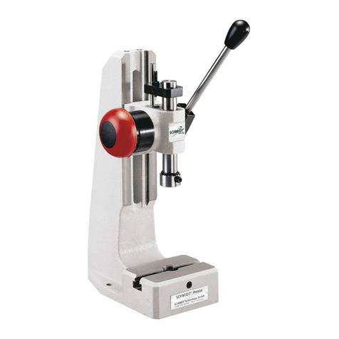
SCHMIDT®Presses à crémaillère No. 3 - 6
SCHMIDT®Rack-and-Pinion Presses No. 3 - 6
SCHMIDT®Zahnstangenpressen Nr. 3 - 6
course retour totalisateur mec.
R =avec blocage de la Z =avec compteur
R =with return stroke lock Z =with mechanical counter
R = mit Rückhubsperre Z =mit mech.Summenzähler
Betriebsanleitung
Operator's manual
Mode d'emploi
Version 07. 2008
SCHMIDT Technology GmbH
Feldbergstraße 1
D-78112 St.Georgen / Germany
Tel. +49 (77 24) 899 0
Fax +49 (77 24) 899 101
info@schmidttechnology.de
www.schmidttechnology.de
SCHMIDT Technology Corporation
Cranberry Corporate Center
280 Executive Drive
USA - Cranberry Twp., PA 16066
Tel. +1 (724) 772-46 00
Tel. +1 (800) 959-12 18
Fax +1 (724) 772-46 88
[email protected]
www.schmidtpresses.com
SCHMIDT Technology Ltd
Unit 14/18, The Markham Centre
UK - Theale, Reading
BerksRG74PE
Tel. +44 (1 18) 9305-464
Fax +44 (1 18) 9305-440
sales@schmidttechnology.co.uk
www.schmidttechnology.co.uk
SCHMIDT Technology GmbH
Niederlassung Schweiz
Gerbeackerstr. 8
CH-3210 Kerzers
Tel. +41 (0)31 755 40 71
Fax +41 (0)31 755 40 73
infoCH@schmidttechnology.ch
www.schmidttechnology.ch
5180
2.2 Einstellung Arbeitshub
•Arbeitshöhe einstellen (10).
•Anschlagklemmstück (8) lösen, mit Werkzeug auf Werkstück fahren, Anschlagklemmstück festziehen.
•Presstiefe mit Feineinstellung (6) justieren und Sicherungsmutter (7) wieder anziehen.
2. Inbetriebnahme
1Handhebel
2Stößel
3Schieber
4Werkzeugfixierung
5Aufnahmefixierung
6Feineinstellung Arbeitshub
7Sicherungsmutter Arbeitshub
8Anschlagklemmstück
9Anschlag "Untere Totpunktposition" UT
10 Schrauben Schieberklemmung
11 Schrauben Deckblech / Lagerscheibe
12 Deckblech Drehfeder
13 Befestigungsbohrungen Untergestell
14 Klemmschraube Rückhubsperre (Ausf. R)
15 Rastbolzen (Ausf. R)
16 Kurvenscheibe (Ausf. R)
17 Sicherungsring (Ausf. R)
18 Lagerscheibe (Ausf. R)
19 Not-Entriegelungsknopf (Ausf. R)
1hand lever
2ram
3head unit
4ram tool locking screw
5locking screw for workpiece
6fine adjustment for working stroke
7locking nut - working stroke
8stroke reducer
9fixed ram stroke stopper BDC
10 head locking screws
11 screws for cover plate / bearing disc
12 coverplate for torsion spring
13 frame bolt holes
14 locking screw for return stroke lock (R)
15 stop bolt (version R)
16 cam (version R)
17 locking ring (version R)
18 bearing disc (version R)
19 emergency release button (version R)
1levier à main
2coulisseau
3tête
4fixation d’outillage
5fixation d’alésage
6réglage précis, course de travail
7contre-écrou, course de travail
8réduction de course
9arrêt "position point mort bas" PMB
10 vis, serrage de la tête
11 vis, couvercle / disque
12 couvercle, ressort de torsion
13 alésage de serrage, table de travail
14 vis d’arrêt, blocage de la course de retour
(exécution R)
15 boulon d'arrêt (exécution R)
16 came (exécution R)
17 circlip (exécution R)
18 disque (exécution R)
19 bouton d'arrêt d'urgence (exécution R)
1. Pressenaufbau / Mechanical structure / Structure des presses
2.5 Rückhubsperre (optional) Achtung: Mindesthub = 20mm
Bei Veränderung des Arbeitshubes (neue UT - Position) muß die Rückhubsperre neu justiert werden.
•Klemmschraube (14) lösen, bis Kurvenscheibe (16) auf Welle leicht drehbar.
•Pressenstößel mit Handhebel auf Anschlag in UT-Position (9) und festhalten.
•Kurvenscheibe (16) im Uhrzeigersinn drehen, bis diese an Rastbolzen (15) in Ausraststellung anschlägt.
•Klemmschraube (14) fest anziehen.
•Probehub ausführen und Schaltverhalten kontrollieren.
Die Rückhubsperre ist korrekt eingestellt, wenn mit Erreichen des Hubanschlages UT (9) der Rastbolzen (15) über
die Ausrastkante in die Rückhubkurve der Kurvenscheibe (16) gleitet.
Achtung:Wird UT-Position nicht erreicht, bleibt Rückhub gesperrt.
Sperrstellung I = 13,0mm vor UT, Sperrstellung II = 4,5mm vor UT, Ausrastgenauigkeit* 0,07 mm
*Mindestresthub vor UT-Anschlag zum sicheren Ausrasten der Rückhubsperre
1
2
3
4
5
6
7
8
9
10
11
12
13 15
16 17
14
18
2.6 Not-Entriegelung der Rückhubsperre
Durch Eindrücken des Not-Entriegelungsknopfes (19) wird der Rückhub in Sperrstellung I + II in Notsituation freigegeben.
19
2.1 Handhebel
•Handhebel (1) auf Welle aufstecken und mit der Klemmschraube festschrauben.
Anzugsmoment 6 bis maximal 10 Nm (für Presse Nr. 5 = 15 Nm)
Achtung: Die maximale Betätigungskraft am Handhebel beträgt 200 N (nicht überschreiten)
2.3 Einstellen Drehfeder-Rückstellkraft
•Schieber (3) in oberste Arbeitshöheposition stellen und Anschlagklemmstück (8) entfernen.
•Stößel (2) nach unten bewegen, bis Verzahnung außer Eingriff ist.
•Handhebel nach vorne (Kraft größer), nach hinten (Kraft kleiner). Achtung: Feder nicht überspannen
•Stößel (2) und Klemmstück (8) montieren.
2.4 Auswechseln der Drehfeder
•Schrauben (11) lösen und Deckblech (12) entfernen. Achtung: Feder unter Spannung
•Ausführung mit Rückhubsperre: Sicherungsring (17) entfernen, Klemmschraube (14) lösen, Kurvenscheibe abnehmen
und Lagerscheibe (18) abschrauben.
•Neue Drehfeder innen einfetten, austauschen, Deckblech bzw. Rückhubsperre montieren.
Hinweis: Die Feder hängt sich selbsttätig wieder ein.
2.7 Stößel reinigen
•Reinigen Sie den Stößel gelegentlich mit einem leicht geölten Tuch.
•Verwenden Sie auf keinen Fall lösungsmittelhaltige Reiniger, da dies zu Trockenlauf des Stößels führt.
2.3 Adjustment of torsion spring return force
•Locate press head (3) in most upper working height position and remove the stroke reducer (8).
•Move the ram downwards till toothing is out of contact.
•Hand lever (1) forward (force gets higher) hand lever backward (force gets lower).
•Assemble ram (2) and stroke reducer (8).Attention: Don't overstrain the spring.
2.5 Return stroke lock (optional) Attention: requires a minimum of 20 mm of ram stroke
If you change the ram stroke adjustment (new BDC-position), please adjust the return stroke lock.
•Loosen locking screw (14) permitting the turning of cam (16) with slight resistance.
•Move handle until ram is fully extended.
•Turn cam (16) clockwise until stop bolt (15) release position is reached.
•Tighten locking screw (14).
•Check ram stroke for proper release position.
Proper operation of the return stroke lock is predicated on the stop bolt (15) releasing when the press ram has
reached its full extension.
Attention: Should you not be able to reach full extension of the ram stroke then you will be in a locked mode
and the ram can not be returned to its home position.
Block position I = 13mm before B.D.C., block position II = 4,5mm before B.D.C., release precision* 0.07 mm
* Minimum remainder stroke before BDC-limit for safe releasing of the return stroke lock.
2.2 Setting of working height
•Loosen head locking screws (10).
•Unfasten the adjustable stroke reducer (8), move the tool upon the workpiece and retight the adjustable stroke reducer.
•Adjust the press depth by fine tuning of the ram (6), and retight the locking nut (7).
2. Setup instructions
2.2 Réglage de la course de travail
•Régler l’hauteur de travail (10).
•Desserrer la réduction de course (8), conduire l’outil vers la pièce à travailler, serrer la réduction de course.
•Ajuster la profondeur avec le réglage précis (6) et arrêter le contre-écrou (7).
2.6 Déclencheur d’urgence du blocage de la course retour
En pressant le bouton d’arrêt d’urgence (19) la course retour est libérée dans les positions d’arrêt I et II
en cas d’urgence
2.6 Emergency release for return stroke lock
By pressing the emergency release button (19) the return stroke in locked positions I and II is released in emergency sitations
2. Mise en service
2.5 Blocage de la course de retour (optional) Attention: course minimale = 20 mm
En cas de modification de la course de travail (nouvelle position PMB) le blocage de la course de retour doit être
ajusté de nouveau.
•Desserrer la vis d’arrêt (14) jusqu’à-ce-que la came (16) se tourne facilement tournant sur la broche.
•Coulisseau avec levier à main jusqu’à l’arrêt dans la position PMB (9) et maintenir.
•Tourner la came (16) dans le sens des aiguilles d’une montre jusqu’à-ce-que celle-ci soit arrêtée par le boulon
d'arrêt (15) en position de déclenchement.
•Serrer bien la vis d’arrêt (14).
•Faire une course d’épreuve et contrôler l’attitude du couplage.
Le blocage de la course de retour est ajusté correctement quand le boulon d'arrêt (15) glisse, au moment
d’atteindre l’arrêt de la course PMB (9), sur la côté de déclenchement vers la came de course de retour
de la came (16).
Attention: Dans le cas où la position PMB n’est pas atteinte, la course de retour reste bloquée.
Position bloquée I = 13mm avant P.M.B., position bloquée II = 4,5mm avant P.M.B., précision de déclenchement* 0.07 mm
*Le restant minimum de la course avant P.M.B.-arrêt pour débloquer la course retour d’une manière fiable.
2.4 Échange du ressort de tension
•Desserrer les vis (11) et démonter la couvercle (12) Attention: Ressort sous tension.
•Exécution avec course de retour: démonter le circlip (17), desserrer la vis d’arrêt (14), enlever la came et dévisser
le disque (18).
•Lubrifier le nouveau ressort dans l’intérieur, échanger, monter la couvercle ou bien le blocage de la course de retour.
Indication: Le ressort s’accroche de nouveau automatiquement.
2.3 Réglage du ressort de torsion - force du rappel
•Placer la tête (3) dans la position de travail la plus haute et enlever la réduction de course (8).
•Mouvoir le coulisseau (2) vers la bas jusqu’à-ce-que l’engrenage soit hors contact.
•Levier à main en avant (force augmente), en arrière (force diminuit).
•Monter le coulisseau (2) et monter la réduction de course (8). Attention: Ne pas tendre trop le ressort.
2.4 Exchange of the torsion spring
•Unfasten screws (11) and remove coverplate (12). Attention: Spring stands under force.
•Configuration with return stroke lock: remove locking ring (18), unfasten locking screw (14), remove cam and
unscrew bearing disc (19).
•Grease the new torsion spring at the inside, exchange the old one, assemble coverplate and return stroke lock.
Notice:The spring is self slinging.
2.1 Handlever Mount handlever (1) to shaft and tighten it with a clamping screw. The fastening torque is from 6 Nm till max. 10 Nm
(for press No. 5 = 15 Nm)
Attention:The max.operating force at the handlever is 200 N (is not allowed to be exceeded)
2.1 Levier
Monte levier à ‘axe et fixe cela avec la vis de serrage. Le couple de démarrage est de 6 Nm jusqu’ à 10 Nm
(pour presse No. 5 = 15 Nm)
Attention: La force de manoeuvre max. au levier est 200 N .
2.7 Cleaning of Ram
•The ram has needs to be cleaned occassionally with a slightly oiled cloth.
•In any case do not use any solvent based cleaners, in order to avoid any dry running condition of the ram.
2.7 Nettoyage de coulisseau
•Nettoyez le coulissearu occasionnellement avec un chiffon légèrement huilé.
•N' utilisez en aucun cas des substances dissolvantes, parce que cela pourrait causer un courant sec du coulisseau.
Dimensions in paranthesis valid for US - versions only. * = .0008,-.000
3.Technische Daten /Technical data / Caractéristique techniques
20
21
23
22
(350) (0.67-1.57) (2.95x6.30) (2.95x1.96) (2.559) (1.96 - 5.90) (.394) (18)
(525) (0-2.75) (5.90x10.08) (5.90x4.33) (3.386) (3.15 - 8.26) (.787) (48)
kN A mm BxL mm BxT mm C mm D mm E Ømm kg
Order Force Stroke Base Table Over- Working Table Weight
(350) (0 -1.57) (2.95x6.30) (2.95x1.96) (2.559) (1.96 - 5.90) (.394) (18)
32,4 0 - 70 150 x 256 150 x 110 86 80 - 210 20H7 22
(lbs.) (inch) (inch) (inch) (inch) (inch) (inch) (lbs.)
Bestell- Kraft Hub Platz- Tisch- Aus- Arbeits- Tisch- Gewicht
Comm.: sance la base la table cygne de travail table env.
No de Puis- Course Dim. de Dim. de Col de Hauteur Alésage Poids
3R 2,4 18 - 70 150 x 256 150 x 110 86 80 - 210 20H7 22
(525) (0.7-2.75) (5.90x10.08) (5.90x4.33) (3.386) (3.15 - 8.26) (.787) (48)
41,6 0 - 40 75x 160 75 x 50 65 50 - 150 10H7 8
4R 1,6 17 - 40 75x 160 75 x 50 65 50 - 150 10H7 8
number: dim. dim. hang height bore appr.
Nr.: bedarf größe ladung höhe bohrung ca.
(525) (0.7-2.75) (7.28x10.83) (7.28x4.52) (3.386) (4.72-14.17) (.787) (66)
(350) (0 - 1.57) (4.33x7.28) (4.33x3.15) (2.559) (2.36 - 7.08) (.787) (26)
(525) (0-2.75) (7.28x10.83) (7.28x4.52) (3.386) (4.72-14.17) (.787) (66)
51,6 0 - 40 110 x 185 110 x 80 65 60 - 180 20H7 12
5R 1,6 17 - 40 110 x 185 110 x 80 65 60 - 180 20H7 12
(350) (0.67-1.57) (4.33x7.28) (4.33x3.15) (2.559) (2.36 - 7.08) (.787) (26)
62,4 0 - 70 185 x 273 185x115 86 120 - 360 20H7 30
6R 2,4 18 -70 185 x 273 185x115 86 120 - 360 20H7 30
C
L
BxT
BD
A
10H7
(½")
E
3, 3R, 6, 6R X = ca. 55°
4. Zähler (optional) / Counter (optional) / Compteur (optional)
4, 4R, 5, 5R X = ca. 45°
4.2 Montage Zähler
•Hubhebel (22) auf Zählerachse (mit Winkel X)
montieren.
•Zähler (20) mit 2 Schrauben M4 (23) an
Schieber befestigen.
Der Schaltwinkel des Zählers beträgt 15°.
Die Maximaldrehbewegung beträgt 40°.
0°
55°
9999
X
45°
Form-Nr. 1025/07/08/3000/1 409116.30 Technische Änderungen vorbehalten / Technical changes are reserved / Changes techniques sont réservés. Printed in Germany
4.2 Assembly of the counter
•Mount stroke lever (22) on counter’s axis (with angle X).
•Tighten counter (20) with 2 screws M4 (23) on
the head unit.
The Switching angle of the counter is 15°.
Maximal rotation is 40°.
4.2. Installation du compteur
•Monter le levier de course (22) sur l'axe de
compteur (angle X).
•Fixer le compteur (20) avec deux vis M4 (23) à la
tête.
L’angle de couplage du compteur est 15°.
Le mouvement rotatif maximal est 40°.
4.1 Components of the counter
20 mechanical counter
21 holding angle
22 stroke lever
23 fillister head screws M4x8
4.1 Aufbau Zähler
20 Mech. Zähler
21 Haltewinkel
22 Hubhebel
23 Zylinderschrauben M4x8
4.1 Structure du compteur
20 compteur mécanique
21 angle d’arrêt
22 levier de course
23 vis à tête cylindrique M 4x8

Other manuals for 3

1

This manual suits for next models

7

Other Schmidt Power Tools manuals

Schmidt 4 User manual

Schmidt

Schmidt 4 User manual

Schmidt 4 User guide

Schmidt

Schmidt 4 User guide

Schmidt ADS 250 User manual

Schmidt

Schmidt ADS 250 User manual

Schmidt ServoPress 605-660 User manual

Schmidt

Schmidt ServoPress 605-660 User manual

Schmidt 343 User manual

Schmidt

Schmidt 343 User manual

Schmidt AmphiBlast 120 User manual

Schmidt

Schmidt AmphiBlast 120 User manual

Schmidt ManualPress 300 Series User manual

Schmidt

Schmidt ManualPress 300 Series User manual

Schmidt HydroPneumaticPress User manual

Schmidt

Schmidt HydroPneumaticPress User manual

Schmidt 3 User manual

Schmidt

Schmidt 3 User manual

Popular Power Tools manuals by other brands

WABECO F1200 high speed operating instructions

WABECO

WABECO F1200 high speed operating instructions

Jet JJ-6HHDX Operating instructions and parts manual

Jet

Jet JJ-6HHDX Operating instructions and parts manual

Makita AF201Z instruction manual

Makita

Makita AF201Z instruction manual

Worx WX665L owner's manual

Worx

Worx WX665L owner's manual

BGS technic 70057 instruction manual

BGS technic

BGS technic 70057 instruction manual

Orange Electronic M207 user manual

Orange Electronic

Orange Electronic M207 user manual

stayer PR6 operating instructions

stayer

stayer PR6 operating instructions

Panduit RT2HT Operation instructions

Panduit

Panduit RT2HT Operation instructions

Avdel 7539-300X Series instruction manual

Avdel

Avdel 7539-300X Series instruction manual

CAMPAGNOLA SUPER STAR DT quick guide

CAMPAGNOLA

CAMPAGNOLA SUPER STAR DT quick guide

Dukane Infinity Series quick start guide

Dukane

Dukane Infinity Series quick start guide

Slime 40060 manual

Slime

Slime 40060 manual

Fein AMM700 1.7Q AS manual

Fein

Fein AMM700 1.7Q AS manual

Makita DTM41 instruction manual

Makita

Makita DTM41 instruction manual

PYD Life CEHP0708-LB user manual

PYD Life

PYD Life CEHP0708-LB user manual

Black & Decker KS900E Original instructions

Black & Decker

Black & Decker KS900E Original instructions

Roller Akku-Arco 22V Series instruction manual

Roller

Roller Akku-Arco 22V Series instruction manual

RIDGID 918-i manual

RIDGID

RIDGID 918-i manual

manuals.online logo
manuals.online logoBrands
  • About & Mission
  • Contact us
  • Privacy Policy
  • Terms and Conditions

Copyright 2025 Manuals.Online. All Rights Reserved.