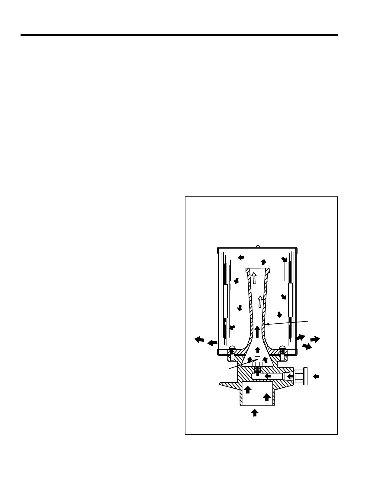
Tornado Dual Internal Air Head Assembly
8
COMPRESSED AIR VACUUM FACTS
1. Use the smallest air jet possible to do the job. The
smaller the jet, the lower the compressed air C.F.M.
required.
2. Use a single venturi unit where liquid recovery is the
primary application. A single venturi will recover liquids
as fast as a double venturi will, yet consumes only one
half as much compressed air.
3. Use a double venturi or quad venturi unit where higher
volume of vacuum air is required. Remember, com-
pressor overload is more likely to occur with a quad
than a double venturi.
4. Use the lowest air line pressure possible per the given
jet size to do the job. The lower the line pressure, the
lower the compressed air consumption.
5. Air line must be maintained at the valve of the venturi
unit. If pressure is not maintained at the unit, vacuum
performance will not be reached. Be sure to use
low line pressure for light liquid recovery, and high
line pressure for liquids, sludge, and other heavy
debris.
6. The air line hose should be as short as possible, and of
maximum inside diameter (single 1/2”, double 3/4”,
quad 1” recommended). Line air losses that occur are
related to hose length and diameter, thus reducing
performance.
7. Any air line moisture (condensation) should be elimin-
ated. Using a water trap in the air line to the venturi unit
will help maintain peak performance.
8. Air line components can reduce performance. Quick
disconnect couplings and line filters, for example, may
reduce compressed air delivery.
9. Factors that affect compressed air supply are com-
pressor horsepower rating, compressor C.F.M. rating,
and system resistance of installed air lines.
Things To Know
AIR COMPRESSOR EVALUATION
Independent of high horsepower or high compressor
C.F.M. rating claims made by individuals, the final evalua-
tion in determining if a compressor is capable of supply-
ing enough compressed air, is to demonstrate the air
vacuum with a pressure gauge at the venturi unit. This
will show the actual pressure being maintained while the
unit is operating (refer to fact #5). This approach will also
compensate for air line system resistance losses. If the
compressor cannot maintain the free air consumption
necessary, the line pressure will drop. Consequently, the
compressed air C.F.M. will also drop, thus reducing the
vacuum or suction performance.
NOTE: The compressed air C.F.M. is not the same as the
vacuum air C.F.M.
VENTURI
AIR JET
WORKING
VACUUM
AIR FLOW
INTERNAL VENTURI
SILENCER MEDIA
SILENCER MEDIA