dymax BlueWave FX-1250 User manual

BlueWave® FX-1250
Large-Area LED Flood System
User Guide

2 U S E R GU I D E |B L U E W A V E ®FX-1250
About Dymax
UV/Visible light-curable adhesives. Systems for light
curing, fluid dispensing, and fluid packaging.
Dymax manufactures industrial, light-curable, epoxy, and
activator-cured adhesives. We also manufacture a complete
line of manual fluid dispensing systems, automatic fluid
dispensing systems, and light-curing systems. Light-curing
systems include LED light sources, spot, flood, and
conveyor systems designed for compatibility and high
performance with Dymax adhesives.
Dymax adhesives and light-curing systems optimize the
speed of automated assembly, allow for 100% in-line
inspection, and increase throughput. System designs
enable stand-alone configuration or integration into your
existing assembly line.
Please note that most dispensing and curing system
applications are unique. Dymax does not warrant the fitness
of the product for the intended application. Any warranty
applicable to the product, its application, and use is strictly
limited to that contained in the Dymax standard Conditions
of Sale. Dymax recommends that any intended application
be evaluated and tested by the user to ensure that desired
performance criteria are satisfied. Dymax is willing to assist
users in their performance testing and evaluation by
offering equipment trial rental and leasing programs to
assist in such testing and evaluations. Data sheets are
available for valve controllers or pressure pots upon
request.

U S E R G U I D E |B L U E W A V E ®FX-1250 3
Contents
Introduction.................................................................................4
Where to Get Help........................................................................................... 4
Safety...........................................................................................4
Product Overview .......................................................................5
Controller Main Components......................................................................... 6
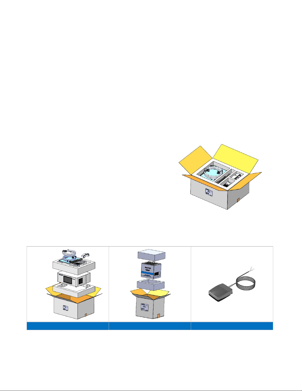
Unpacking ...................................................................................8
Unpacking and Inspecting Your Shipment................................................... 8
Parts Included .................................................................................................. 8
System Installation .....................................................................9
System Assembly............................................................................................ 9
System Cooling................................................................................................ 9
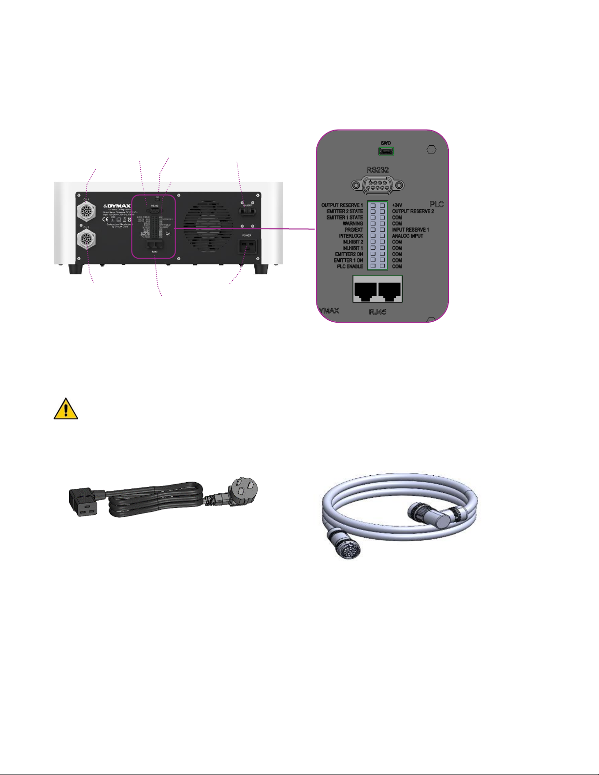
Wiring and Connections ...............................................................................10
Connections ...................................................................................................11
I/O Interface Summary .............................................................12
PLC UV Control .............................................................................................13
Status Output.................................................................................................14
Operation...................................................................................15
Start Up...........................................................................................................15
Main Window Settings ..................................................................................15
Setting the Power ..........................................................................................17
Setting the Cure Time...................................................................................17
Running the System......................................................................................17
Program Setting.............................................................................................18
Settings......................................................................................19
Brightness.......................................................................................................19
Clock and Calendar Settings .......................................................................20
Resetting the Emitters’ LED ON Time.........................................................20
Changing the Password................................................................................20
System Reset .................................................................................................20
System Log ....................................................................................................21
PLC Mode ..................................................................................22
Spare Parts & Accessories ......................................................24
Specifications ...........................................................................25
Declaration of Conformity........................................................28
Validation...................................................................................30
Warranty....................................................................................31

4 U S E R G U I D E |B L U E W A V E ®FX-1250
Introduction
This guide describes how to set up, use, and maintain the
BlueWave®FX-1250 LED flood-curing system safely and efficiently.
Intended Audience
This user guide is meant for experienced process engineers,
technicians, and manufacturing personnel. If you are new to high-
intensity LED light sources and do not understand the instructions,
contact Dymax Application Engineering for answers to your
questions before using the equipment.
Where to Get Help
Dymax Customer Support and Application Engineering teams are
available by phone in the United States, Monday through Friday,
from 8:00 a.m. to 5:30 p.m. Eastern Standard Time. You can also
Dymax locations can be found on the back cover of this user guide.
Additional resources are available to ensure a trouble-free
experience with our products:
•Detailed product information on our website www.dymax.com
•Dymax adhesive product data sheets on our website
•Safety data sheets (SDS) provided with shipments of Dymax
materials
Safety
WARNING! If you use this UV light source without first
reading and understanding the information in the UV Light
Safety Guide, SAF001, injury can result from exposure to high-
intensity light. To reduce the risk of injury, please read and ensure
you understand the information in that guide before assembling and
operating the Dymax UV LED light source.
This device falls under IEC 62471 Risk Group 3 for UVA and Blue
Light emissions:
WARNING! UV emitted from this product. Avoid eye and skin
exposure to unshielded products.
WARNING! Possibly hazardous optical radiation emitted from this
product. Do not look at operating lamp. Eye injury may result.

U S E R G U I D E |B L U E W A V E ®FX-1250 5
Product Overview
The BlueWave FX-1250 is a high-intensity LED flood system used for curing light-curable materials. The unit is designed to be
integrated into a larger system, such as an automated manufacturing system, or used with a light shielding enclosure to create
a bench-top curing station.
The BlueWave FX-1250 can be used for manual and automated process applications and is composed of a controller and LED
flood emitter, which is available in three different wavelengths: VisiCure (405 nm), PrimeCure (385 nm), and RediCure (365
nm).
The controller portion consists of an integrated control module and power supply. It allows complete control of an LED emitter,
including setting intensity, timing, operation, and programming, while reporting the identity, operating parameters, and status of
the emitter. It is designed to be used with any of the three LED emitter wavelengths. It is available in one channel (1CH) and
two channel (2CH) configurations. The 2CH supports any two emitters, regardless of wavelength, working at the same time.
System Name
BlueWave FX-1250
Controller Model
BlueWave FX-1250 1CH
BlueWave FX-1250 2CH
Emitter Model
BlueWave FX-1250 RediCure
BlueWave FX-1250 PrimeCure
BlueWave FX-1250 VisiCure
The BlueWave FX-1250 functions as a flood-curing system with a 127 mm x 127 mm (5 in x 5 in) irradiated curing area.
The unit can be operated in admin mode (unrestricted control) or production mode (restricted control) which allows for
process management via access restrictions.
The unit can be controlled as well by Programmable Logic Controller (PLC) for automation applications.
LED technology within the BlueWave FX-1250 LED Flood System allows for instant on/off activation without the need for a
warm-up period and is also rated for continuous operation.
Figure 1.
BlueWave FX-1250 LED Flood Curing System

6 U S E R G U I D E |B L U E W A V E ®FX-1250
Controller Main Components
The interactive parts of the controller include the Display Screen, Power Switch, Power Input Receptacle, Output CH1 ,Output CH2 , RS232
Receptacle, RS485 Receptacle and PLC Interface.
Figure 2.
Controller Front Panel
Figure 3.
Controller Back Panel
Display Screen: Controls the operation of the controller and displays the operation parameters.
Power Switch: Controls the controller’s power.
Power Input Receptacle: Used to connect the power cord.
Output CH 1, CH2: Used to connect the connection cord. There is no difference between the two receptacles, and they can
be connected randomly.
RS485 & RS232 Receptacle: Used to communicate with a UVCS 3.0 conveyor. No connection is required when the controller
is used alone.
PLC Interface: Used to connect to a PLC.
Display Screen
Power Switch
Power Input Receptacle
Output CH1
RS232 Receptacle
PLC Interface
Output CH2
RS485 Receptacle

U S E R G U I D E |B L U E W A V E ®FX-1250 7
Table 1.
Labels
Warning Labels
Product Information
Label
High Temperature
Caution Label
Emitter Wavelength
Label
(RediCure, PrimeCure, or
VisiCure)

8 U S E R G U I D E |B L U E W A V E ®FX-1250
Unpacking
Unpacking and Inspecting Your Shipment
Upon arrival, inspect all boxes for damage and notify the shipper of box damage immediately. Open each box and check for
equipment damage. If parts are damaged, notify the shipper and submit a claim for the damaged parts. Contact Dymax so that
new parts can be shipped to you immediately.
The parts below are included in every package/order. If parts are missing from your order, contact your local Dymax
representative or Dymax Customer Support to resolve the problem.
Inspect the glass for any damage or residue on the surface. Carefully clean the glass with the alcohol swab. Take care not to
touch the glass with bare hands, as any residue left on the window can adversely affect performance on the unit.
Parts Included
•BlueWave FX-1250 Controller
•BlueWave FX-1250 Emitter (RediCure, PrimeCure,
or VisiCure, model as selected at time of purchase)
•Power Cord
•Connection Cable (controller to emitter)
•BlueWave FX-1250 LED Flood System User Guide
(document not shown)
•Terminal Block (plugged on the BlueWave FX-1250 controller)
•Footswitch
•Safety Eyewear
Figure 4.
System Packaging
Figure 5.
Components of the BlueWave FX-1250 Curing System
Controller Packaging
Emitter Packaging
Footswitch (CE Compliant)

U S E R G U I D E |B L U E W A V E ®FX-1250 9
System Installation
System Assembly
The system includes two major parts, the controller and
emitter. The two parts are shipped separately.
To assemble the two parts together, plug one side of the
connection cable into the controller and the other side
into the emitter (Figure 6).
NOTE: Be careful to keep the glass at the bottom of the
emitter clean. To avoid leaving fingerprints on the glass,
do not touch the glass with bare hands.
WARNING! The BlueWave FX-1250 is
designed and certified to operate as instructed
within this document. Alteration of the system or
its component installation may pose a shock
hazard.
Figure 6.
Connection Cable Installed
System Cooling
The system can be used in various scenarios with additional mounting fixtures or Dymax accessories, i.e., as a bench-top unit
with a stand on a chamber, as part of a conveyor, etc. This system should only be operated in a location that provides proper
cooling. Location requirements are as follows:
•For proper cooling of the unit, upper intake and lower exhaust must not be blocked.
•Minimum recommended clearance is 8 inches [200 mm].
•Note that the lower exhaust may have one side blocked for installations where two units are side by side. The system will
operate safely but run hotter.
Figure 7.
Recommended Cooling Clearance

10 U S E R G U I D E |B L U E W A V E ®FX-1250
Wiring and Connections
All the wire and cable connections are located on the rear of the controller or the top of emitter.
Figure 8.
Controller Connections
Power Switch: Turns the unit on and off.
Power Input: The power cord plugs in here. Only use the power cord supplied by Dymax (Figure 9) as the power cord
supplied with the controller is specifically designed and certified to work with the controller.
WARNING! The BlueWave FX-1250 is designed and certified to operate with the Dymax supplied 16 Amp, 1.5 mm², 3
conductor power cord. Do not use any other non-standard power cord.
Figure 9.
Power Cord
Figure 10.
Connection Cable for Output Channels 1 & 2
Output CH1/CH2: Output power and control signal to emitter. Only use the connection cable supplied by Dymax (Figure 10)
as the connection cable supplied with the controller is specifically designed for this system. One controller in 2CH
configuration can support up to two emitters at the same time.
SWD: Burn in or update the software into controller.
RS232: Conduct communication to computer.
PLC: Controlled by PLC program.
RS485: Controlled by internet.
Output CH1
Power Input
Output CH2
Power Switch
RS485
RS232
SWD
PLC

U S E R G U I D E |B L U E W A V E ®FX-1250 11
Connections
The connection cable has two 15P plugs that connect the controller to the emitter.
Plugging the connection cable into the controller: Roll the plug clockwise while inserting to plug the cable in. Roll the plug
counterclockwise while removing to unplug the cable (Figure 11).
Plugging the connection cable into the emitter: Roll the plug clockwise while inserting to plug the cable in. Roll the plug
counterclockwise while removing to unplug the cable (Figure 12).
Figure 11.
Plug Connection Cable into Controller
Figure 12.
Plug Connection Cable into Emitter
Attention: When plugging in the female and male connectors, observe the key and keyway of each connector. The key should
align with the keyway (Figure 13).
Figure 13.
Key (Left) and Keyway (Right)

12 U S E R G U I D E |B L U E W A V E ®FX-1250
I/O Interface Summary
Table 1 below shows the summary of all signals on the PLC Connector.
Table 2.
I/O Interface
Signal Name / Description
PIN #
Signal Level
Asserted
De-Asserted
INPUTS
Input Reserve 1
14
Do Not Use
ANALOG INPUT
Only used in PLC EXT mode
Sets Emitter intensity level (0~1V=0% output,1V=10% output,
10V=100% output)
12
0 –10 VDC
N/A
INTERLOCK
11
0 VDC, GND
(Open)
PLC ENABLE
1
0 VDC, GND
(Open)
Emitter 1 ON
3
0 VDC, GND
(Open)
Emitter 2 ON
5
0 VDC, GND
(Open)
PRG/EXT
13
0 VDC, GND(EXT)
(Open)(PRG)
INHIBIT 1
7
0 VDC, GND
(Open)
INHIBIT 2
9
0 VDC, GND
(Open)
OUTPUTS
PLC POWER (1)
(24V, 50mA maximum)
22
Always On
WARNING
15
0 VDC, GND
Open
EMITTER 1 STATE
17
0 VDC, GND
Open
EMITTER 2 STATE
19
0 VDC, GND
Open
Output Reserve 1, Output Reserve 2
21,20
Do Not Use
RETURNS (These pins are common and may be used interchangeably)
COM
2,4,6,8,1
0,16,18
Common Grounds
(1) PLC power channel is a 24V source available for use to drive PLC logic but must be current limited using pull-down resistors to protect the BlueWave FX-1250
when directly attached to the I/O channels through the PLC connector.
(2) CHASSIS Ground connections do not share a common connection with signal returns and cannot be interchanged with signal returns.

U S E R G U I D E |B L U E W A V E ®FX-1250 13
PLC UV Control
PLC switching may be driven by manual switch, relay, or optical coupler. Only analog intensity uses a voltage input to the PLC.
To use the PLC mode, the PLC ENABLE (input pin 1) must be pulled down to low by grounding to the COM ground point
The PLC INTERLOCK (input Pin 11) disables all the UV output when it is de-asserted. It is pulled down before other control
signal in PLC mode.
The PLC INHIBIT 1 (input Pin 7) and INHBIT 2 (input Pin 9) disables each channel’s UV output when it is de-asserted. After the
INTERLOCK is pulled down, the INHIBIT 1 or INHIBIT 2 is also pulled down.
After above signals are pulled down, the PLC can control the UV on/off using the Emitter 1 ON (input Pin 3) or Emitter 2 ON
(input Pin 5). When this input is pulled down by grounding to COM ground, the UV LED will turn on.
The PLC can also control the intensity of the UV output.
•When the PRG/EXT (input Pin 13) is pulled down low by grounding to COM ground, the Intensity will be controlled by
the EXTERNAL ANALOG INTENSITY input voltage.
•The ANALOG INPUT (input Pin 12) is an analog voltage input. The voltage range is 0 to 10VDC.
Any setting below 1 VDC will set the Intensity to 0% and each 1V additional volt increases intensity by 10%. (Example: 1V =
10%, 5V = 50%, 10V = 100%). The example connection for the PLC control signal is shown in Figure 14.
Figure 14.
PLC Connection Example

14 U S E R G U I D E |B L U E W A V E ®FX-1250
Status Output
There are three status outputs. They are driven by an optical
coupler. These outputs work in any mode and can be used as
status inputs for PLC or any status display/monitor purpose.
•WARNING - Output low indicates the unit is working
normally.
•Emitter 1 & 2 State - Output low indicates the UV LEDs
are ON.
An example application of these signals is shown in Figure 15.
PLC Power channel is a 24V source available for use to drive
PLC logic but must be current limited using pull-down resistors
to protect the FX-1250 when directly attached to the I/O
channels through the PLC connector. The support current is
50 mA max
Figure 15.
Status Outputs Connection Using On-Board 24V Source
Figure 16.
PLC Status Outputs Using Customer-Supplied 24V Source
Figure 17.
Examples of Customer Configurations for Monitoring Outputs

U S E R G U I D E |B L U E W A V E ®FX-1250 15
Operation
Start Up
1. Verify all connectors are firmly plugged into the rear panel of the
BlueWave FX-1250 controller and emitter.
2. On the rear panel of the controller, move the power switch to the
ON position (up direction).
3. The start-up window (Figure 18) will appear for several seconds
as the system initializes.
4. After starting up, the main window (Figure 19) appears.
WARNING! Emitters must be installed correctly before power up.
If no emitter is installed, the controller is not operable. Power off
the controller and install at least one emitter.
5. The system is now ready to have emitter parameters set.
Main Window Settings
In the main window, the operator can:
1. Set each channel’s power and cure time.
2. Start or stop each channel or all channels.
Figure 18.
Start-Up Window
Figure 19.
Main Window
1
2
3
4
5
6
7
8
9
10

16 U S E R G U I D E |B L U E W A V E ®FX-1250
Table 3.
Main Window Functions
Number
Name
ICON
Description
1
System setting
Press to enter the system setting window to set the
system parameters (clock, calendar, password, LED on
time, brightness).
2
Calendar and clock
Display clock and calendar.
3
Progress bar
If the cure time is not zero, the green bar increases to
indicate the progress of a cure time count.
If the cure time is zero, the green bar does not increase.
LED on time displays the total time the LED has been
on.
4
Play/Stop button
Each channel controls one emitter.
The green color indicates the emitter is on.
is pressed to start the emitter.
is pressed to stop the emitter.
The red indicates the emitter is off when you just plug
one emitter.
The dark grey indicates no emitter is plugged in. Power
off the controller to install an emitter.
The red and dark grey play button have no function
when pressed.
5
Emitter &
parameters
Each channel can be connected to an emitter. It
displays the channel number on top.
6
Power and type
button
Displays the channel number, emitter type, power set.
The display will be one of four colors:
Blue -- RediCure,
Black -- VisiCure
Grey -- PrimeCure
Red -- NA
Press to set the power of this channel.
If no emitter is plugged in, the channel displays NA.
7
Timer
Counts down to zero if the cure time is not zero.
Counts up if the cure time is zero.
Press to set the cure time.
8
Program
Press to save and load stored setting parameters.
9
Stop button
Press to stop all emitters.
10
Run button
Press to start all emitters. When at least one of the
emitters is on, the ‘RUN’ turns to ‘RUNNING’.

U S E R G U I D E |B L U E W A V E ®FX-1250 17
Setting the Power
The operation steps are:
1. On the main window, press the power button (Table 3,
#6) to enter the power window (Figure 20).
2. Enter the desired value using the pad and press enter.
(10%~100%). The new value will display in the bar.
3. If no change is needed, press the back arrow in the top
left corner to exit the power window.
Setting the Cure Time
1. On the main window, press the timer (Table 3, #7) to
enter the cure time window (Figure 21).
2. Enter the desired value using the pad and press enter.
(0-9999 seconds). The new value will display in the bar.
Set the cure time to 0 sec. to run the emitter until it is
manually stopped.
Set a value greater than 0 sec. to run the emitter
automatically for that duration.
Cure times can be set in intervals of 0.1 sec.
3. If no changes are needed, press the back arrow in the left
top corner to exit the cure time window.
Running the System
1. After power and cure time have been set, the emitters can
be run.
2. Each emitter channel can be operated separately using the
play/stop button (Table 3, #4) on the main window.
3. To operate all emitter channels together, the run
(Table 3, #10) and stop (Table 3, #9) buttons on the main
window can be used to start and stop the emitters.
Figure 20.
Power Window
Figure 21.
Cure Time Window

18 U S E R G U I D E |B L U E W A V E ®FX-1250
Program Setting
To save your set values in the main window, press program (Table 3, #8) on the main window to enter the program setting
window. You are required to enter the user’s password correctly before the program window (Figure 22) loads.
Figure 22.
Program Window
There are 16 slots for selection. Their default names are Program # (1-16). Only one slot can be selected at a time.
The operation steps are:
1. Press on a program slot. The program slot will change to blue when selected. The parameters stored in that program slot
will display in the white bar.
2. Press the Rename button to rename the slot.
3. Press the Save button to save the current set values (channel number, power, and cure time) to that program slot.
4. Press the Load button to load the slot’s value and exit to the main window.
5. Press the Delete button to erase a slot’s name and set the stored values of the slot to 0.
6. Press the back arrow in the top left corner to exit the program window.

U S E R G U I D E |B L U E W A V E ®FX-1250 19
Settings
Press the system setting button on the main window. A password input window (Figure 23) will appear. The password
must be entered to enter the System Settings window.
Press the input bar on the password input window to activate the keyboard (Figure 24).
The default password is set to “1234”.
Figure 23.
Password Input Bar
Figure 24.
Keypad for Password Window
Once the password is entered, the System Settings window (Figure 25) will appear.
Figure 25.
System Settings Window
Figure 26.
Brightness Adjustment Bar
Brightness
1. On the system settings window, press on the brightness dropdown button (Figure 26).
2. Move the bar up and down to adjust the brightness of the screen.
3. Press the back arrow in the left top corner to exit.

20 U S E R G U I D E |B L U E W A V E ®FX-1250
Clock and Calendar Settings
1. On the system settings window, press the time dropdown
arrow.
2. Press the clock in the window to input the date
and time by using the pad.
3. Press the back arrow on the top left to exit.
Resetting the Emitters’ LED ON Time
The emitter on time appears in the gray bar (Figure
28) on the System Settings window.
Once the emitter is on, the LED on time will begin
counting.
If an emitter is changed for a channel, the LED on time
must be cleared for it to recount in that channel.
Press the Reset button located to the right of the
emitter LED on time to clear it.
Changing the Password
1. Press the change Password button on the system
settings window to enter the Change Password
window.
2. Press New Password to input the new password.
3. Press “Confirm New Password”and input the new
password again. The two input passwords must be the
same.
4. Press the back arrow in the left top corner to exit.
System Reset
Press the System Reset button on the System Settings
window to:
•Reset the password to the default:1234
•Reset the program names and values to the default
Figure 27.
Clock and Time Input Pad
Figure 28.
Emitter On Time
Figure 29.
Change Password Window
Table of contents
Other dymax Industrial Equipment manuals

dymax
dymax BlueWave 200 User manual

dymax
dymax Tridak 1001 User manual

dymax
dymax BlueWave AX-550 Programming manual

dymax
dymax BlueWave MX-150 User manual

dymax
dymax BlueWave AX-550 User manual

dymax
dymax BlueWave MX-250 User manual

dymax
dymax SD-100 User manual

dymax
dymax BlueWave 200 Programming manual

dymax
dymax ZIP User manual

dymax
dymax T40571 User manual