Toro 03188 User manual

FormNo.3443-362RevB
27-inch5,8,or11-Bladeor
32-inch8-BladeEdgeSeries™
DPACuttingUnit
Reelmaster®3100-Dor3105-DTractionUnit
ModelNo.03188—SerialNo.407900000andUp
ModelNo.03189—SerialNo.407900000andUp
ModelNo.03190—SerialNo.407900000andUp
ModelNo.03191—SerialNo.407900000andUp
ModelNo.03192—SerialNo.400000000andUp
Registeratwww.Toro.com.
OriginalInstructions(EN)*3443-362*

ThisproductcomplieswithallrelevantEuropean
directives.Fordetails,pleaseseetheDeclarationof
Incorporation(DOI)atthebackofthispublication.
Introduction
Thiscuttingunitisdesignedforcuttinggrasson
well-maintainedlawnsingolfcourses,parks,sports
elds,andoncommercialgrounds.Usingthisproduct
forpurposesotherthanitsintendedusecouldprove
dangeroustoyouandbystanders.
Readthisinformationcarefullytolearnhowtooperate
andmaintainyourproductproperlyandtoavoid
injuryandproductdamage.Youareresponsiblefor
operatingtheproductproperlyandsafely.
Visitwww.Toro.comforproductsafetyandoperation
trainingmaterials,accessoryinformation,helpnding
adealer,ortoregisteryourproduct.
Wheneveryouneedservice,genuineT oroparts,or
additionalinformation,contactanAuthorizedService
DealerorT oroCustomerServiceandhavethemodel
andserialnumbersofyourproductready.Figure1
identiesthelocationofthemodelandserialnumbers
ontheproduct.Writethenumbersinthespace
provided.
Important:Withyourmobiledevice,youcan
scantheQRcodeontheserialnumberplate(if
equipped)toaccesswarranty,parts,andother
productinformation.
g280515
Figure1
1.Locationofthemodelandserialnumbers
ModelNo.
SerialNo.
Thismanualidentiespotentialhazardsandhas
safetymessagesidentiedbythesafety-alertsymbol
(Figure2),whichsignalsahazardthatmaycause
seriousinjuryordeathifyoudonotfollowthe
recommendedprecautions.
g000502
Figure2
Safety-alertsymbol
Thismanualuses2wordstohighlightinformation.
Importantcallsattentiontospecialmechanical
informationandNoteemphasizesgeneralinformation
worthyofspecialattention.
©2021—TheToro®Company
8111LyndaleAvenueSouth
Bloomington,MN554202
Contactusatwww.Toro.com.
PrintedintheUSA
AllRightsReserved

Contents
Safety.......................................................................3
GeneralSafety...................................................3
CuttingUnitSafety..............................................4
BladeSafety.......................................................4
SafetyandInstructionalDecals..........................4
Setup........................................................................5
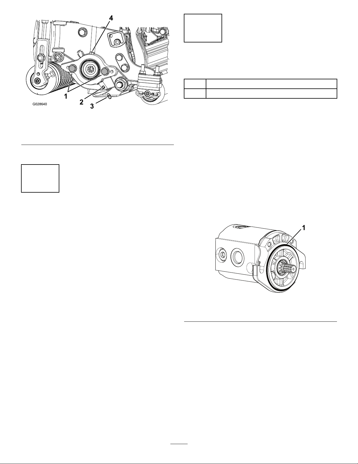
1InstallingtheReelGreaseFitting......................5
2AdjustingtheCuttingUnit.................................6
3InstallingtheReelMotors.................................6
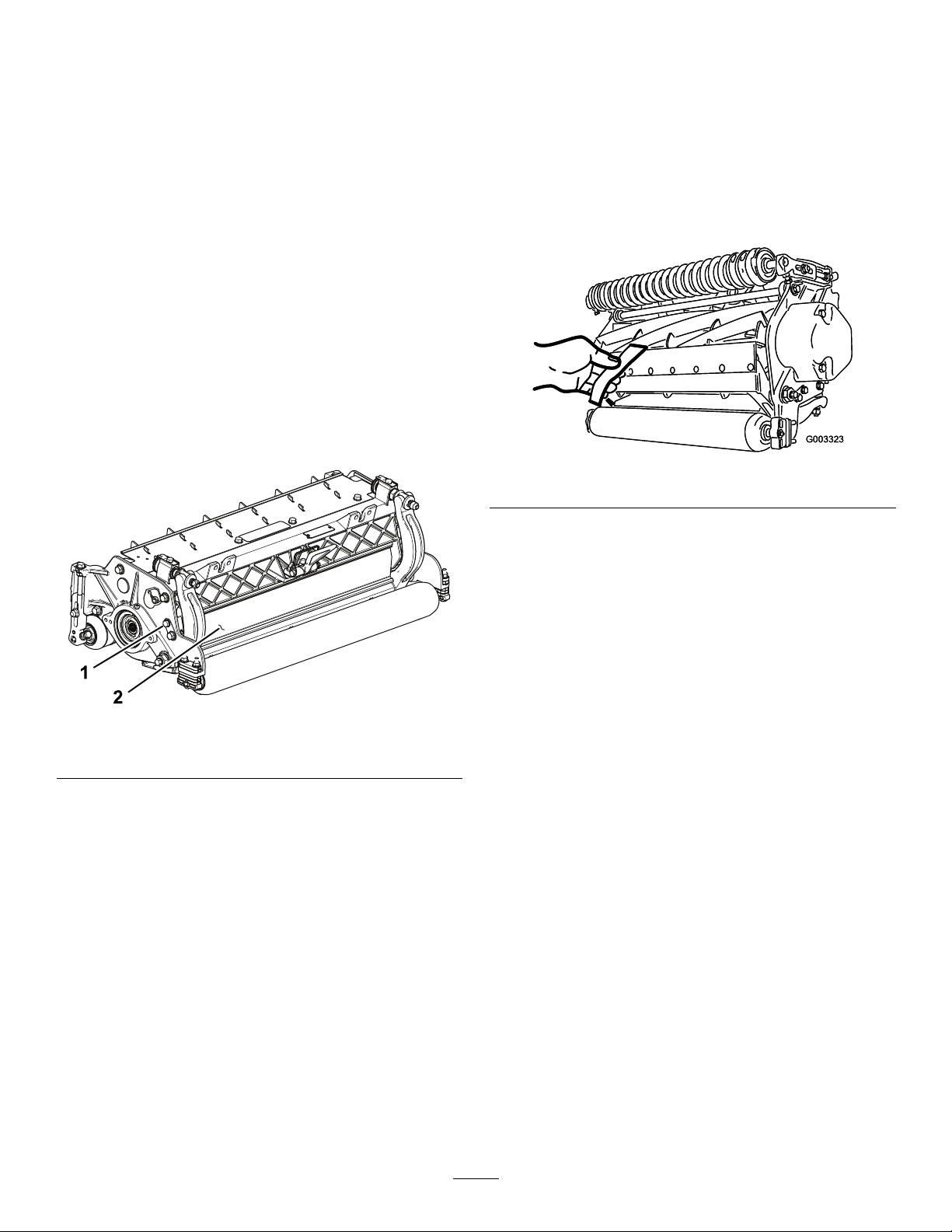
4AdjustingtheShopRollerAssemblies..............7
ProductOverview.....................................................7
Specications....................................................7
Attachments/Accessories...................................7
Operation..................................................................8
AdjustingtheCuttingUnit...................................8
AdjustingtheShopRollerAssemblies................11
AdjustingtheHeightofCut(HOC).....................12
AdjustingtheHeightofCut(HOC).....................14
Height-of-CutChartTerms................................16
Maintenance...........................................................17
UsingtheKickstandwhenTippingthe
CuttingUnit...................................................17
LubricatingtheCuttingUnits.............................17
Relief-GrindingtheReel...................................18
InstallingtheFrontShaftAssemblyforReel
Grinding........................................................19
ServicingtheBedknife.....................................20
ServicingtheBedbar........................................21
ServicingtheHDDualPointAdjusters
(DPA)............................................................23
ServicingtheRoller...........................................24
Safety
Thismachinehasbeendesignedinaccordancewith
ENISO5395andANSIB71.4–2017.
GeneralSafety
Thisproductiscapableofamputatinghandsandfeet.
Alwaysfollowallsafetyinstructionstoavoidserious
personalinjury.
•Readandunderstandthecontentsofthis
Operator’sManualbeforestartingthemachine.
•Useyourfullattentionwhileoperatingthe
machine.Donotengageinanyactivitythat
causesdistractions;otherwise,injuryorproperty
damagemayoccur.
•Donotputyourhandsorfeetnearmoving
componentsofthemachine.
•Donotoperatethemachinewithoutallguards
andothersafetyprotectivedevicesinplaceand
functioningproperlyonthemachine.
•Keepclearofanydischargeopening.
•Keepbystandersandchildrenoutoftheoperating
area.Neverallowchildrentooperatethemachine.
•Beforeyouleavetheoperator’sposition,dothe
following:
–Parkthemachineonalevelsurface.
–Lowerthecuttingunit(s).
–Disengagethedrives.
–Engagetheparkingbrake(ifequipped).
–Shutofftheengineandremovethekey.
–Waitforallmovementtostop.
Improperlyusingormaintainingthismachinecan
resultininjury.T oreducethepotentialforinjury,
complywiththesesafetyinstructionsandalways
payattentiontothesafety-alertsymbol,which
meansCaution,Warning,orDanger—personalsafety
instruction.Failuretocomplywiththeseinstructions
mayresultinpersonalinjuryordeath.
3

CuttingUnitSafety
•Thecuttingunitisonlyacompletemachinewhen
installedonatractionunit.Readthetraction
unitOperator’sManualcarefullyforcomplete
instructionsonthesafeuseofthemachine.
•Stopthemachine,removethekey(ifequipped),
andwaitforallmovementtostopbeforeinspecting
theattachmentafterstrikinganobjectorifthere
isanabnormalvibrationinthemachine.Makeall
necessaryrepairsbeforeresumingoperation.
•Keepallpartsingoodworkingconditionandall
hardwaretightened.Replaceallwornordamaged
decals.
•Useonlyaccessories,attachments,and
replacementpartsapprovedbyToro.
BladeSafety
Awornordamagedbladecanbreak,andapieceof
thebladecouldbethrowntowardyouorbystanders,
resultinginseriouspersonalinjuryordeath.
•Inspectthebladeperiodicallyforwearordamage.
•Usecarewhencheckingtheblades.Wrapthe
bladesorweargloves,andusecautionwhen
servicingtheblades.Onlyreplaceorsharpenthe
blades;neverstraightenorweldthem.
•Onmulti-bladedmachines,takecareasrotating1
bladecancauseotherbladestorotate.
SafetyandInstructionalDecals
Safetydecalsandinstructionsareeasilyvisibletotheoperatorandarelocatednearanyarea
ofpotentialdanger.Replaceanydecalthatisdamagedormissing.
decal137-9706
137-9706
1.Cuttinghazardofthehandorfoot—shutofftheengine,
removethekeyordisconnectthesparkplug,waitforall
movingpartstostop,andreadtheOperator’sManual
beforeperformingmaintenance.
4

Setup
LooseParts
Usethechartbelowtoverifythatallpartshavebeenshipped.
ProcedureDescriptionQty.Use
1Straightgreasetting1Installthereelgreasetting.
2Nopartsrequired–Adjustthecuttingunit
O-ring1
3Capscrews(maycomeassembled)2Installthereelmotors.
4Nopartsrequired–Adjusttheshoprollerassembly
positions(Model03192only).
MediaandAdditionalParts
DescriptionQty.Use
Operator'sManual1
PartsCatalog(notincluded)—refertothe
includedpostcardforinformationonobtaining
thePartsCatalog.
–Reviewthematerialandsaveitinanappropriateplace.
Note:Determinetheleftandrightsidesofthe
machinefromthenormaloperatingposition.
1
InstallingtheReelGrease
Fitting
Partsneededforthisprocedure:
1Straightgreasetting
Procedure
Installthegreasettingonthereel-motorsideof
thecuttingunit.RefertoFigure3todeterminethe
positionofthereelmotorsbasedonthepositionofthe
cuttingunitonthemachine.
g034633
Figure3
1.Cuttingunit14.Weight
2.Cuttingunit25.Reelmotor
3.Cuttingunit3
1.Removeanddiscardthesetscrewonthe
reel-motorsideplate(Figure4).
5

g028640
Figure4
1.Capscrew(2)3.Greasetting
2.Setscrew4.Greasevent
2.Installthestraightgreasetting(Figure4).
2
AdjustingtheCuttingUnit
NoPartsRequired
Procedure
1.Adjustthebedknifetothereel.
2.Adjusttherearrollerforyourheight-of-cut
requirements.
3.Settheheightofcut.
4.Adjusttherearshieldifnecessary.
RefertoAdjustingtheCuttingUnit(page8)
forcompleteinstructionsforperformingthese
adjustments.
3
InstallingtheReelMotors
Partsneededforthisprocedure:
1O-ring
2Capscrews(maycomeassembled)
Procedure
Important:Beforeinstallingthereelmotors,
obtainandinstallthecounterweightsorother
accessoriesontheoppositesideofthecutting
unitsfromthereelmotorsasdescribedin
theinstructionsprovidedwiththeweightsor
accessories.
1.Installthecuttingunitsontothetractionunit;
refertothetractionunitOperator’sManualsfor
instructions.
2.Iftherearenocapscrewsonthereel-motorside
plate,installthem(Figure4).
3.InstalltheO-ringonthereelmotor(Figure5).
g191072
Figure5
1.O-ring
4.Installthereelmotorandsecureitwiththecap
screws.
5.Greasethesideplateuntilexcessgreasecomes
outofthegreasevent(Figure4).
6

4
AdjustingtheShopRoller
Assemblies
Model03192Only
NoPartsRequired
Procedure
Adjusttheshoprollerpositionsbeforeoperatingthe
cuttingunitsforthersttime;refertoAdjustingthe
ShopRollerAssemblies(page11).
ProductOverview
Specications
ModelNumberWeight
0318857kg(125lb)
0318960kg(132lb)
0319062kg(136lb)
0319167kg(147lb)
0319254kg(119lb)
Attachments/Accessories
AselectionofToroapprovedattachmentsand
accessoriesisavailableforusewiththemachine
toenhanceandexpanditscapabilities.Contact
yourAuthorizedServiceDealerorauthorizedToro
distributororgotowww.Toro.comforalistofall
approvedattachmentsandaccessories.
Toensureoptimumperformanceandcontinuedsafety
certicationofthemachine,useonlygenuineT oro
replacementpartsandaccessories.Replacement
partsandaccessoriesmadebyothermanufacturers
couldbedangerous,andsuchusecouldvoidthe
productwarranty.
7

Operation
RefertoyourtractionunitOperator’sManualfor
detailedoperationinstructions.Beforeusingthe
cuttinguniteachday,adjustthebedknife;referto
AdjustingtheBedknifetotheReel(page9).Testthe
qualityofcutbycuttingatestswathbeforeusingthe
cuttingunittoensurethatthenishedcutiscorrect.
AdjustingtheCuttingUnit
AdjustingtheRearShield
Undermostconditions,youcanattainthebest
clippingdispersionwhentherearshieldisclosed
(frontdischarge).Whenconditionsareheavyorwet,
youmayopentherearshield.
Toopentherearshield(Figure6),loosenthebolt
securingtheshieldtotheleftsideplate,rotatethe
shieldtotheopenposition,andtightenthebolt.
g191341
Figure6
1.Bolt2.Rearshield
CheckingtheCuttingUnit
Thedualknobbedknife-to-reeladjustmentsystem
incorporatedinthiscuttingunitsimpliesthe
adjustmentprocedureneededtodeliveroptimum
mowingperformance.Thepreciseadjustment
possiblewiththedualknob/bedbardesigngives
thenecessarycontroltoprovideacontinual
self-sharpeningaction-thusmaintainingsharpcutting
edges,ensuringgoodqualityofcut,andgreatly
reducingtheneedforroutinebacklapping.
Priortomowingeachday,orasrequired,checkeach
cuttingunittoverifyproperbedknife-to-reelcontact.
Performthisprocedureevenwhenthequalityof
cutisacceptable.
1.Slowlyrotatethereelinareversedirection,
listeningforreel-to-bedknifecontact.
Note:Theadjustmentknobshavedetents
correspondingto0.022mm(0.0009inch)
bedknifemovementforeachindexedposition.
RefertoAdjustingtheBedknifetotheReel
(page9).
2.Testthecuttingperformancebyinsertingalong
stripofcuttingperformancepaper(T oroPartNo.
125-5610)betweenthereelandthebedknife,
perpendiculartothebedknife(Figure7).Slowly
rotatethereelforward;itshouldcutthepaper.
g003323
Figure7
Note:Ifexcessivecontact/reeldragisevident,
eitherbacklap,refacethefrontofthebedknife,
orgrindthecuttingunittoachievethesharp
edgesneededforprecisioncutting;refertoReel
MowerBasics,FormNo.09168SL.
Important:Lightcontactispreferred
atalltimes.Ifyoudonotmaintainlight
contact,thebedknifeandreeledgeswill
notsufcientlyself-sharpenandwilldull
afteraperiodofoperation.Ifyoumaintain
excessivecontact,thebedknifeandreelwill
wearmorequicklyandunevenly,andthe
qualityofcutmaybeadverselyaffected.
Note:Afterextendedrunning,aridgewill
eventuallydevelopatbothendsofthebedknife.
Roundofforlethesenotchesushwiththe
cuttingedgeofthebedknifetoensuresmooth
operation.
Note:Overtime,youwillneedtogrindthe
chamfer(Figure8),asitisonlydesignedtolast
40%ofthebedknifelife.
8

g031270
Figure8
1.Lead-inchamferonright
endofbedknife
3.1.5mm(0.060inch)
2.6mm(0.25inch)
Note:Donotmakethelead-inchamfertoo
largeasitmaycauseturftufting.
AdjustingtheBedknifetotheReel
Usethisproceduretosetthebedknifetothereeland
tochecktheconditionofthereelandbedknifeand
theirinteraction.Aftercompletingthisprocedure,
alwaystestthecuttingunitperformanceunderyour
eldconditions.Youmayneedtomakefurther
adjustmentstoobtainoptimalcuttingperformance.
Important:Donotovertightenthebedknifetothe
reeloryouwilldamageit.
•Afterbacklappingthecuttingunitorgrindingthe
reel,youmayneedtomowwiththecuttingunitfor
afewminutesandthenperformthisprocedure
toadjustthebedknifetothereelasthereeland
bedknifeadjusttoeachother.
•Youmayneedadditionaladjustmentsiftheturfis
extremelydenseoryourcuttingheightisverylow.
Youwillneedthefollowingtoolstocompletethis
procedure:
•Shim0.05mm(0.002inch)(PartNo.125-5611)
•Cuttingperformancepaper(PartNo.125-5610)
1.Positionthecuttingunitonaat,levelwork
surface.
2.Turnthebedbar-adjustingscrews
counterclockwisetoensurethatthebedbardoes
notcontactthereel(Figure9).
g003322
Figure9
1.Bedbar-adjustingscrew
3.Tipthecuttingunittoexposethebedknifeand
reel.
Important:Makesurethatthenutsonthe
backendofthebedbar-adjustingscrews
arenotrestingontheworksurface;usethe
kickstand(Figure10).
g191340
Figure10
1.Kickstand
4.Rotatethereelsothatabladecrossesthe
bedknifeapproximately25mm(1inch)infrom
theendofthebedknifeontherightsideofthe
cuttingunit.
Note:Putanidentifyingmarkonthisbladeto
makesubsequentadjustmentseasier.
5.Insertthe0.05mm(0.002inch)shimbetween
themarkedreelbladeandthebedknifeatthe
pointwherethebladecrossesthebedknife.
6.Turntherightbedbaradjusterclockwiseuntil
youfeellightpressure(i.e.drag)ontheshim,
thenbackoffthebedbaradjuster2clicksand
removetheshim.
9

Note:Adjusting1sideofthecuttingunitaffects
theotherside,the2clickswillprovideclearance
forwhentheothersideisadjusted.
Note:Ifstartingwithalargegap,bothsides
shouldinitiallybedrawncloserbyalternately
tighteningtherightandleftsides.
7.Slowlyrotatethereelsothatthesameblade
thatyoucheckedontherightsideiscrossing
thebedknifeapproximately25mm(1inch)in
fromtheendofthebedknifeontheleftsideof
thecuttingunit.
8.Turntheleftbedbaradjusterclockwiseuntilthe
shimcanbeslidthroughthereeltobedknife
gapwithlightdrag.
9.Returntotherightsideandadjustasnecessary
togetlightdragontheshimbetweenthesame
bladeandbedknife.
10.Repeatsteps8and9untiltheshimcanbeslid
throughbothgapswithslightdrag,but1clickin
onbothsidespreventstheshimfrompassing
throughonbothsides.
Note:Thebedknifeisnowparalleltothereel.
Note:Thisprocedureshouldnotbeneeded
ondailyadjustments,butshouldbedoneafter
grindingordisassembly.
11.Fromthisposition(i.e.,1clickinandshimnot
passingthrough)turnthebedbaradjusters
clockwise1clickeach.
Note:Eachclickturnedmovesthebedknife
0.022mm(0.0009inch).Donotovertighten
theadjustingscrews.
12.T estthecuttingperformance;refertoChecking
theCuttingUnit(page8).
AdjustingtheRearRoller
1.Adjusttherearrollerbrackets(Figure11)tothe
desiredheight-of-cutrangebypositioningthe
requiredamountofspacersbelowtheside-plate
mountingange(Figure11)pertheHOCChart.
g003324
Figure11
1.Spacer3.Side-platemountingange
2.Rollerbracket
2.Raisetherearofthecuttingunitandplacea
blockunderthebedknife.
3.Removethe2nutssecuringeachrollerbracket
andspacertoeachside-platemountingange.
4.Lowertherollerandscrewsfromtheside-plate
mountingangesandspacers.
5.Placethespacersontothescrewsontheroller
brackets.
6.Securetherollerbracketandspacersto
undersideofsideplatemountingangeswith
thenutspreviouslyremoved.
7.Verifythatthebedknife-to-reelcontactiscorrect.
Tipthemowertoexposethefrontandrear
rollersandbedknife.
Note:Thepositionoftherearrollertothereel
iscontrolledbythemachiningtolerancesofthe
assembledcomponents;therefore,parallelingis
notrequired.Alimitedamountofadjustmentis
possiblebysettingthecuttingunitonasurface
plateandlooseningtheside-platemountingcap
screws(Figure12).Adjustandtightenthecap
screws.T orquethecapscrewsto37to45N·m
(27to33ft-lb).
g020698
Figure12
1.Side-platemountingcapscrews
10

AdjustingtheShopRoller
Assemblies
Model03192Only
Beforeyoulowerthecuttingunitstotheshopooror
removethemfromthetractionunit,lowertheshop
rollerassembliestoprotectthereelandbedknife
bladesfromhardsurfacecontact.
Beforeoperatingthecuttingunits,installthemtothe
machine,raisethecuttingunits,andraisetheshop
rollerassembliestopreventthemfromtouchingthe
grassandinterferingwithoperation.
1.Removethecotterpinfromtheclevispinthat
securestheshoprollerbrackettothesideplate.
2.Positiontheshoprollerassemblyasneeded:
•Lowertheshoprollerbracketsbeforethe
cuttingunitisloweredtotheshopooror
removedfromthetractionunit(Figure13).
g341821
Figure13
1.Clevispin(alwaysinstalled
inthetopsquareholein
thesideplate)
3.Shoprollerassembly(in
lowered/shopposition)
2.Sideplate
•Raisetheshoprollerbracketsafterthe
cuttingunitisraisedtotheoperatingposition
(Figure14).
g341820
Figure14
1.Clevispin(alwaysinstalled
inthetopsquareholein
thesideplate)
3.Shoprollerassembly(in
raised/operatingposition)
2.Sideplate
Note:Ensurethattheclevispinisalways
installedinthetopsquareholeintheside
plate.
3.Securetheshoprollerbrackettotheclevispin
withthecotterpin.
4.Repeatthisprocedureontheoppositeendof
thecuttingunit,andforallothercuttingunitsas
needed.
11

AdjustingtheHeightofCut
(HOC)
Models03188,03189,03190,and
03191Only
Note:UseHeight-of-CutChart(Models03188,
03189,03190,and03191)todeterminethe
numberofrearspacersneededforthedesired
aggressiveness-of-cutsetting;refertoHeight-of-Cut
Chart(Models03188,03189,03190,and03191)
(page13).
1.Loosenthelocknutssecuringtheheight-of-cut
bracketstothecutting-unitsideplates(Figure
15).
g015089
Figure15
1.Adjustingscrew3.Height-of-cutbracket
2.Locknut
2.Loosenthenutonthegaugebar(Figure16)
andsettheadjustingscrewtothedesiredheight
ofcut.
Note:Thedistancebetweenthebottomofthe
screwheadandthefaceofthebaristheheight
ofcut.
g011864
Figure16
1.Gaugebar3.Nut
2.Height-adjustingscrew
3.Hookthescrewheadonthecuttingedgeofthe
bedknifeandresttherearendofthebaronthe
rearroller(Figure17).
4.Rotatetheadjustingscrewuntilthefrontroller
contactsthegaugebar(Figure17).Adjustboth
endsofrolleruntiltheentirerollerisparallelto
thebedknife.
g011865
Figure17
Important:Whensetproperly,therear
andfrontrollerswillcontactthegauge
barandthescrewwillbesnugagainstthe
bedknife.Thisensuresthattheheight-of-cut
isidenticalatbothendsofthebedknife.
5.Tightenthenutstosecureadjustment.
Note:Donotovertightenthenuts.Tighten
themjustenoughtoremoveanyplayfromthe
washer.
12

Height-of-CutChart(Models03188,03189,03190,and03191)
HOCSettingAggressiveness
ofCut
No.of1/4inch
RearSpacers
HOCSettingAggressiveness
ofCut
No.of1/4inch
RearSpacers
Less0Less4
Normal0Normal5
6mm(0.250inch)
More1
32mm(1.250
inches)
More6
Less0Less4
Normal1Normal5
9mm(0.375inch)
More2
35mm(1.375
inches)
More6
Less0Less5
Normal1Normal6
13mm(0.500inch)
More2
38mm(1.500
inches)
More7
Less1Less6
Normal2Normal7
16mm(0.625inch)
More3
41mm(1.625
inches)
More8
Less2Less6
Normal3Normal7
19mm(0.750inch)
More4
44mm(1.750
inches)
More8
Less2Less7
Normal3Normal8
22mm(0.875inch)
More4
48mm(1.875
inches)
More9
Less3Less7
Normal4Normal8
25mm(1.000inch)
More5
51mm(2.000
inches)
More9
Less4
Normal5
29mm(1.125
inches)
More6
13

AdjustingtheHeightofCut
(HOC)
Model03192Only
OnModel03192,adjusttheheightofcut(HOC)
byaddingorremovingtheadjustment(slotted)rear
spacersbelowthesideplatepadonthecuttingunit.
Note:Spacersinstalledabovethesideplatepaddo
notaffectHOC.
Theadjustment(slotted)rearspacersarestored
abovethesideplatepad;toincreaseHOC,move
thembelowthesideplatepad.
Thereare2typesofslottedrearspacersusedfor
adjustingHOConModel03192cuttingunits:
•1/4inch(6.4mm)slottedrearspacers,upto3on
eachside.
•0.075inch(1.9mm)thinslottedrearspacers,up
to2oneachside.
Additionallythereare5xedrearspacers(1/4inch,
6.4mm)alwayslocatedbelowthesideplatepad.
Important:Donotremoveoradjustthe5lower
rearspacers;thiscuttingunitisdesignedto
operateataHOCbetween1.25to2.00inches(32
to51mm)andremovingthelowerxedspacers
causestheHOCtoleavethatrange.
g341920
Figure18
1.Thin(0.075inch)
adjustmentspacers
3.Sideplatepad
2.1/4inchadjustment
spacers
4.Lowerxedspacers(do
notadjust)
Height-of-CutChart(Model03192)
HOCSettingNo.of1/4inch
RearSpacers*
No.ofThin
RearSpacers*
32mm(1.25inches)50
34mm(1.33inches)51
35mm(1.38inches)52
38mm(1.50inches)60
40mm(1.58inches)61
42mm(1.65inches)62
45mm(1.75inches)70
46mm(1.83inches)71
48mm(1.90inches)72
51mm(2.00inches)80
*Installedbeneaththesideplatepad.
ToadjusttheaggressivenessofcutonModel
03192cuttingunits,proceedasfollows:
•Installthecuttingunitontothetractionunitas
describedinthetractionunitOperator'sManual.
•Loosen,butdonotremove,thelocknutsatthe
frontofthexedplatesandremovethecarriage
bolts,spacers,andlocknutsfromtherearofthe
xedplatesandadjusttheirposition.
Note:Toachievealessaggressivecut,mount
thecuttingunitlinksinthenumber1positionor
mountthelinkstothenumber3positionfora
moreaggressivecut(Figure19).
g341875
Figure19
Leftsideshown
1.Lessaggressive3.Moreaggressive
2.Production/Standard4.Justloosenthese
locknutsbeforeadjusting
aggressivenessofcut
14

Usethefollowingcharttodeterminewhichbedknifeisbestsuitedforthedesiredheightofcut.
Bedknife/Height-of-CutChart(ProductionBedknife)
BedknifePartNo.BedknifeLipHeightHeightofCut
120-1641(27inch)5.6mm6.4to12.7mm
LowHOC
120-1642(32inch)(0.220inch)(0.250to0.500inch)
112-8910(27inch)6.9mm9.5to50.8mm
EdgeMax®
112-8956(32inch)(0.270inch)(0.375to2.00inches)*
114-9388(Model03188/89/90,27inch)6.9mm9.5to50.8mm
Standard
114-9389(Model03191,32inch)(0.270inch)(0.375to2.00inches)*
114-9390(Model03192,27inch)9.3mm12.7to50.8mm
HeavyDuty
114-9391(32inch)(0.370inch)(0.500to2.00inches)
*Warm-seasongrassesmayrequiretheLowHOCbedknifefor12.7mm(0.500inch)andbelow.
g006510
Figure20
1.Bedknifelipheight*
15

Height-of-CutChartTerms
Height-of-CutSetting(HOC)
Thiscorrespondstothedesiredheightofcut.
Bench-SetHeightofCut
Thebench-setheightofcutistheheightatwhich
thetopedgeofthebedknifeissetaboveaatlevel
surfacethatcontactsthebottomofboththefrontroller
andtherearroller.
EffectiveHeightofCut
Thisistheactualheightthatthegrasshasbeencut.
Foragivenbench-setheightofcut,theactualheight
ofcutvariesdependingonthetypeofgrass,time
ofyear,turf,andsoilconditions.Thecutting-unit
setup(aggressivenessofcut,rollers,bedknives,
attachmentsinstalled,turf-compensationsettings,
etc.)alsoaffecttheeffectiveheightofcut.
ChecktheeffectiveheightofcutusingToroTurf
Evaluatorsregularlytodeterminethedesired
bench-setheightofcut.
RecommendedT oroTurfEvaluatorsformeasuring
ToroReelmasterEffectiveHOC(Figure21):
•TurfEvaluator,Model04399:forbench-setHOC
from0.25to1.00inch(6to25mm).
•HighHeight-of-CutTurfEvaluator,Model
136-3635:forbench-setHOCfrom1.00to2.00
inches(25to51mm).
g342500
Figure21
1.TurfEvaluator—effectiveHOCrange:0.00to1.60inches
(0to41mm)
2.HighHOCTurfEvaluator—effectiveHOCrange:0.75to
6.00inches(19to152mm)
AggressivenessofCut
Theaggressivenessofcuthasasignicantimpacton
theperformanceofthecuttingunit.Aggressiveness
ofcutreferstotheangleofthebedkniferelativetothe
ground(Figure22).
Thebestcutting-unitsetupdependsonyourturf
conditionsanddesiredresults.Experiencewiththe
cuttingunitonyourturfwilldeterminethebestsetting
touse.Youcanadjusttheaggressivenessofcut
throughoutthecuttingseasontoallowforvariousturf
conditions.
Ingeneral,lesstonormalaggressivesettings
aremoreappropriateforwarm-seasongrasses
(Bermuda,paspalum,zoysia)whilecool-season
grasses(bent,bluegrass,rye)mayrequirenormalto
moreaggressivesetups.Moreaggressivesetupscut
moregrassoffbyallowingthespinningreeltopull
moregrassupintothebedknife.
g011863
Figure22
1.Rearspacers3.Aggressivenessofcut
2.Side-platemountingange
RearSpacers
Thenumberofrearspacersdeterminesthe
aggressivenessofcutforthecuttingunit.Foragiven
heightofcut,addingspacersbelowtheside-plate
mountingangeincreasestheaggressivenessofthe
cuttingunit.Allcuttingunitsonagivenmachinemust
besettothesameaggressivenessofcut(number
ofrearspacers,PartNo.119-0626),otherwisethe
after-cutappearancecouldbenegativelyaffected
(Figure22).
16

Maintenance
UsingtheKickstandwhen
TippingtheCuttingUnit
Wheneverthecuttingunithastobetippedtoexpose
thebedknife/reel,propuptherearofthecuttingunit
withthekickstand(suppliedwiththetractionunit)to
makesurethatthenutsonthebackendofthebedbar
adjustingscrewsarenotrestingontheworksurface
(Figure23).
g191340
Figure23
1.Kickstand
LubricatingtheCutting
Units
Regularlylubricatethe5greasettingsofeachcutting
unit(Figure24)withNo.2lithiumgrease.
Thereare2lubricationpointsonthefrontroller,2on
therearroller,and1atthereel-motorspline.
Note:Model03192doesnothaveafrontroller;there
areonlythe2lubricationpointsontherearrollerand
1atthereel-motorspline.
Important:Lubricatingthecuttingunits
immediatelyafterwashinghelpspurgewaterout
ofthebearingsandincreasesbearinglife.
1.Wipeeachgreasettingwithacleanrag.
2.Applygreaseuntilcleangreasecomesoutof
therollersealsandthebearingreliefvalve.
3.Wipeanyexcessgreaseaway.
g191601
Figure24
Greasettingsonthereel-motorside
1.Bearingreliefvalve
17

Relief-GrindingtheReel
Thenewreelhasalandwidthof1.3to1.5mm(0.050
to0.060inch)anda30°reliefgrind.
Whenthelandwidthgetslargerthan3mm(0.120
inch)wide,dothefollowing:
1.Applya30°reliefgrindonallreelbladesuntil
thelandwidthis1.3mm(0.050inch)wide
(Figure25).
g028800
Figure25
1.30°2.1.3mm(0.050inch)
2.Spingrindthereeltoachieve<0.025mm(0.001
inch)reelrun-out.
Note:Thiscausesthelandwidthtogrow
slightly.
Note:Toextendthelongevityofthesharpness
oftheedgeofthereelandthebedknife—after
grindingthereeland/orthebedknife—check
thereeltobedknifecontactagainaftercutting2
fairways,asanyburrswillberemoved,which
maycreateimproperreeltobedknifeclearance
andthusacceleratewear.
3.Usingdiametermeasuringtape,measurethe
outsidediameterofthereelatbothends(Figure
26);thedifferenceinoutsidediameterbetween
theendsshouldbelessthan0.010inches
(0.250mm).Ifthedifferenceisgreater,grindto
correctthedifference.
Note:Outsidediametermeasuringtapeis
availablefromyourauthorizedT orodistributor.
g342519
Figure26
1.Measuretheoutsidediameterofthereelbetweenthe2
outermostinternalsupportsatbothendsandcompare.
18

InstallingtheFrontShaft
AssemblyforReelGrinding
Model03192Only
Important:Youmustorderthefollowingpartsso
thatthecuttingunitcanbettedtoareelgrinding
machine:
Qty.PartPartNo.
2FrontHOCbracket125-2796
2Carriagebolt(3/8x1-1/2
inches)
3231-4
2Locknut(3/8inch)104-8301
2Hex-headbolt(5/16x
1-1/8inches)
322-16
1Frontrollershaft117-0957
1.Removetheshoprollerassemblies(ifequipped);
refertoAdjustingtheShopRollerAssemblies
(page11).
2.Usingthecarriageboltsandlocknuts,install
frontHoCbracketstothetopholeoftheside
plate(Figure27).
Important:EnsurethattheHOCbracketis
installedwiththecarriageboltatthetopof
theslot,sothattheHOCbracketisaslow
aspossible.
g361153
Figure27
1.Carriagebolt(3/8x1-1/2
inches)
4.Hex-headbolt(5/16x
1-1/8inches)
2.Frontrollershaft5.Locknut(3/8inch)
3.FrontHOCbracket
3.InstalltheshafttothebottomoftheHOC
bracketsusingthe2hex-headbolts.
4.Ensurethattheshaftisparalleltothecutting
unit;ifitisnot,loosenthecarriageboltonthe
lowsideandtightenitagainwhentheshaftis
parallel.
19

ServicingtheBedknife
Thebedknifeservicelimitsarelistedinthefollowingchart.
Important:Operatingthecuttingunitwiththebedknifebelowtheservicelimitmayresultinpoor
after-cutappearanceandreducethestructuralintegrityofthebedknifeforimpacts.
BedknifeServiceLimitChart(ProductionBedknife)
BedknifePartNo.BedknifeLipHeightServiceLimit*Top/FrontGrind
Angles
120-1641(27inch) LowHOC
120-1642(32inch)5.6mm(0.220inch)4.8mm(0.190inch)10/5°
112-8910(27inch) EdgeMax®
112-8956(32inch)6.9mm(0.270inch)4.8mm(0.190inch)10/5°
114-9388(Model03188/89/90,27inch) Standard
114-9389(Model03191,32inch)6.9mm(0.270inch)4.8mm(0.190inch)10/5°
114-9390(Model03192,27inch)
HeavyDuty
114-9391(32inch)9.3mm(0.370inch)4.8mm(0.190inch)10/5°
g027268
Figure28
RecommendedTopandFrontBedknifeGrindAngles
1.Bedknifeservicelimit*
2.T opgrindangle
3.Frontgrindangle
Note:Allbedknifeservicelimitmeasurementsrelate
tothebottomofthebedknife(Figure29).
g007165
Figure29
CheckingtheTopGrindAngle
Theanglethatyouusetogrindyourbedknivesis
veryimportant.
Usetheangleindicator(T oroPartNo.131-6828)and
theangle-indicatormount(T oroPartNo.131-6829)to
checktheanglethatyourgrinderproducesandthen
correctforanygrinderinaccuracy.
1.Placetheangleindicatoronthebottomsideof
thebedknifeasshowninFigure30.
g034113
Figure30
1.Bedknife(vertical)2.Angleindicator
2.PresstheAltZerobuttonontheangleindicator.
3.Placetheangle-indicatormountontheedgeof
thebedknifesothattheedgeofthemagnetis
matedwiththeedgeofthebedknife(Figure31).
Note:Thedigitaldisplayshouldbevisiblefrom
thesamesideduringthisstepasitwasinstep1.
20
This manual suits for next models
4
Table of contents
Other Toro Lawn Mower manuals

Toro
Toro 22196 User manual

Toro
Toro Groundmaster 31902 User manual

Toro
Toro Recycler 20379 User manual

Toro
Toro Groundsmaster 4000 Series User manual

Toro
Toro Reelmaster 5410-D User manual

Toro
Toro 29732 User manual

Toro
Toro 30609 User manual

Toro
Toro 30071 User manual

Toro
Toro GrandStand 74568TE User manual

Toro
Toro 22290 User manual

Toro
Toro 74385 TimeCutter ZS 3200 User manual

Toro
Toro 74904 User manual

Toro
Toro 20340 User manual

Toro
Toro 20099 User manual

Toro
Toro GrandStand Revolution TURBO FORCE 18560 User manual

Toro
Toro 30403 User manual

Toro
Toro TimeCutter Z5000 User manual

Toro
Toro 30739 User manual

Toro
Toro 21025 User manual

Toro
Toro 30430 User manual