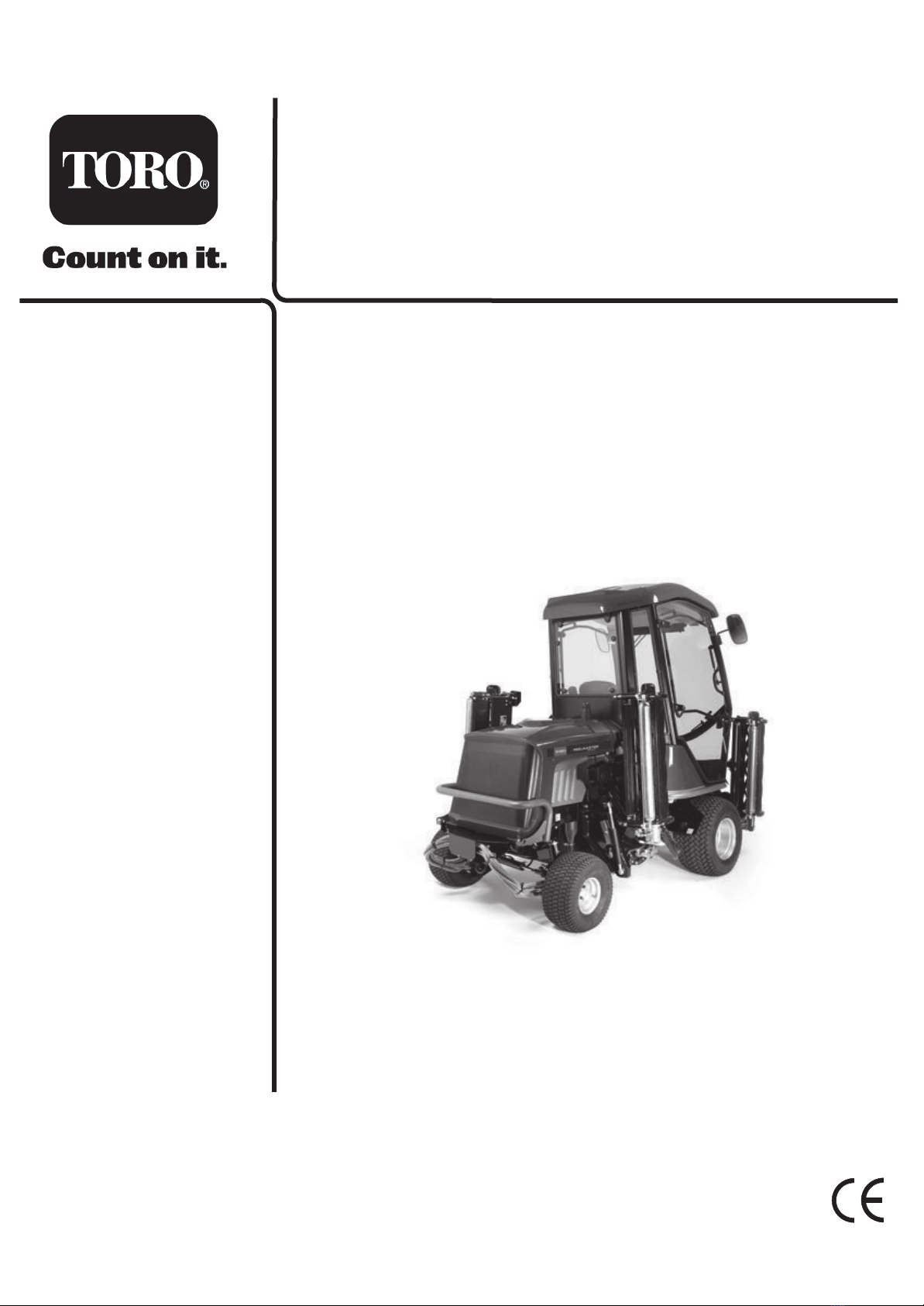
Toro 652D User manual

Part No. 111-0473 Rev B
Reelmaster 4240-D
Code: 652D-Serial No. from 260000001
Operator’s Manual
Original Instructions (EN)


ATTENTION
THIS SYMBOL MEANS
BE ALERT!
YOUR SAFETY IS INVOLVED
READ THIS MANUAL BEFORE USING THE REELMASTER® 4240-D.
IT IS ESSENTIAL THAT OPERATORS STUDY IT FOR THEIR OWN SAFETY.
ALL OPERATORS SHOULD SEEK AND OBTAIN PROFESSIONAL AND
PRACTICAL INSTRUCTIONS ON THE SAFE USE OF THE MOWER. THESE
SERVICES ARE AVAILABLE THROUGH TORO APPROVED COMMERCIAL DEALERS.

CONTENTS
1.4 1.4
CONTENTS
SAFETY PRECAUTIONS.
Training.
Preparation.
Operation.
Handling and storage of fluids.
Maintenance and storage.
Decals.
EC CONFORMITY INFORMATION.
Noise levels.
EC Declaration of Conformity.
INTRODUCTION.
SPECIFICATIONS.
Engine.
Transmission system.
Cutterhead drive system.
Cutterhead lift system and steering.
Hydraulic system.
Vehicle specifications.
Operator controls.
Instrumentation.
Weight and dimensions.
Recommended lubricants and hydraulic fluids.
Cutterheads.
OPERATING THE MOWER.
Safety notice.
Operator presence controls.
Identification of controls.
Braking system.
Throttle control.
Travel.
Work/Transport modes.
Transport latches.
Differential lock.
Travel control pedals.
Forward travel speed backstop lever.
Operator platform latching mechanism.
Adjustable steering column.
Operator seat.
Warning systems.
Audible warning horn.
Ignition key.
Engine pre-heat indicator light.
Page No.
1.6 - 1.14
1.6
1.6 - 1.7
1.7 - 1.9
1.10
1.11
1.12 - 1.14
1.15 - 1.16
1.15
1.16
1.17
1.18 - 1.24
1.18
1.19
1.19
1.20
1.20
1.21
1.22
1.22
1.23
1.23
1.24
1.25 - 1.44
1.25
1.25
1.26
1.27
1.27
1.27
1.28
1.28
1.29
1.29
1.30
1.30
1.31
1.32
1.33
1.33
1.34
1.34

CONTENTS
1.5 1.5
CONTENTS Continued.
Fuel level gauge.
Hourmeter.
Transmission neutral indicator light.
Cutterhead drive switch indicator light.
Parking brake indicator light.
Hydraulic return filter indicator light.
Hydraulic transmission filter indicator light.
Transmission system ‘Work’ mode indicator light.
Cutterhead position control.
Dual lift configuration control.
Cutterhead drive engagement.
Weight transfer/traction assistance.
Starting the engine.
Stopping the engine.
General operating hints.
Unblocking cutting cylinders.
Cutterhead general information.
MK3 200mm Fixed Cutterhead.
MK3 254mm Fixed Cutterhead.
MK3 200mm Floating Cutterhead.
MAINTENANCE.
General safety and good practice.
Engine.
Running in period.
Running in period - at first 50 hours.
Daily and before use.
Every 50 hours.
Every 250 hours.
Every 500 hours.
Cutterhead cylinder to bottom blade adjustment.
Cutterhead backlapping.
Cutterhead grinding.
Cutterhead bottom blade replacement.
Raising the mower off the ground.
Towing the mower.
GRASS CUTTING FAULTS.
TROUBLE SHOOTING.
ELECTRICAL CIRCUIT DIAGRAM.
TRANSMISSION/BRAKE HYDRAULIC CIRCUIT.
HYDRAULIC CIRCUIT DIAGRAM.
WARRANTY.
NOTES.
CUSTOMER INFORMATION.
Page No.
1.34
1.34
1.35
1.35
1.35
1.35
1.35
1.35
1.36
1.36
1.37
1.38
1.38 - 1.39
1.39
1.40
1.41
1.42
1.43
1.43
1.44
1.45 - 1.64
1.45 - 1.46
1.47
1.47
1.47 - 1.48
1.49 - 1.52
1.53 - 1.54
1.55
1.56 - 1.58
1.59
1.60
1.61
1.61
1.62
1.63 - 1.64
1.65 - 1.67
1.68 - 1.74
1.75 - 1.78
1.79 - 1.80
1.81 - 1.82
1.83 - 1.84
1.85
1.86

SAFETY PRECAUTIONS
1.6 1.6
TRAINING
Read the instructions carefully. Be familiar with the controls and the proper use of the equipment. Learn
how to stop the mower quickly in an emergency.
Never allow children or people unfamiliar with these instructions to use the mower. Local regulations
may restrict the age of the operator.
Never mow while people, especially children, or pets are nearby.
Keep in mind that the operator or user is responsible for accidents or hazards occurring to other people or
their property.
Do not carry passengers.
All drivers should seek and obtain professional and practical instruction. Such instruction should emphasise:
The need for care and concentration when working with this machine.
The need to slow down when making tight turning manoeuvres. Failure to take adequate care can affect
stability leading to loss of control of the machine particularly when operating in transport mode.
Control of a ride-on-machine sliding on a slope will not be regained by application of the brake.
The main reasons for loss of control are:
- Insufficient wheel grip.
- Being driven too fast.
- Inadequate braking.
- The type of machine is unsuitable for the task.
- Lack of awareness of the effect of ground conditions, especially slopes.
- Incorrect load distribution.
PREPARATION
Check that the machine complies with all applicable regulations, including those in force when used on
the public highway.
While mowing, always wear substantial footwear and long trousers. Do not operate the equipment when
barefoot or wearing open sandals. Eye protection should be worn.
Thoroughly inspect the area where the equipment is to be used and remove all objects which can be
thrown by the machine.
Never operate the machine without first checking that the operator platform latching mechanism is fully
engaged and in good working order, refer - ‘OPERATOR PLATFORM LATCHING MECHANISM’.
READ THIS MANUAL BEFORE USING THE REELMASTER® 4240-D, IT IS ESSENTIAL
THAT OPERATORS STUDY IT FOR THEIR OWN SAFETY.
THE FOLLOWING PRECAUTIONS MUST BE TAKEN TO HELP PREVENT ACCIDENTS.
A CAREFUL OPERATOR WHO USES COMMON SENSE IS THE SAFEST OPERATOR.
-
-
-

1.7 1.7
SAFETY PRECAUTIONS
PREPARATION Continued.
Ensure that the cutterheads are fully raised with the latches and safety locks engaged in position before
transporting the mower.
Replace faulty silencers.
Check the condition of the tyres and ensure that they are inflated to the correct pressures, refer -
SPECIFICATIONS.
This is particularly important if the machine is to be taken on the public highway.
Check that the mower is in good working order, paying particular attention to the brakes and steering.
Also ensure that the forward/reverse speed control pedals move freely to neutral when released.
Before use, always visually inspect to see that the blades, blade bolts and cutting cylinders are not worn
or damaged. Replace worn or damaged components.
Check the mower hydraulic system, particularly the hydraulic hoses, fittings and hose supports. Worn,
crushed or damaged hoses can burst, with risks to health and damage to the machine and surrounding
turf areas.
After refuelling and adding oil to the hydraulic oil tank ensure that the caps are replaced securely.
Check that all linkages, connections and pivot nuts are secure and that wheel nuts are torqued correctly,
refer - SPECIFICATIONS.
Before operating the machine, ensure that there are no foreign objects or liquids on the platform or ped-
als - ALWAYS KEEP THE OPERATOR PLATFORM CLEAR/CLEAN.
OPERATION
Do not operate the engine in a confined space where dangerous carbon monoxide fumes can collect.
Mow only in daylight or in good artificial light.
Before attempting to start the engine, engage the parking brake, disengage the cutterhead drive system
and ensure that the forward/reverse speed controls are in the neutral position.
Never operate the machine without first checking that the operator platform latching mechanism is fully
engaged and in good working order, refer - OPERATOR PLATFORM LATCHING MECHANISM.
Stored energy devices are charged when the outer wing units are in the transport position. Always oper-
ate the relevant lift controls to provide hydraulic support for the wing units suspensions before attempt-
ing to release the transport latches.

1.8 1.8
SAFETY PRECAUTIONS
OPERATION Continued.
Do not use on a slope of more than 19 degrees. Care should be taken when using the mower on any slope
where ground conditions are such that there may be a risk of the mower rolling over. The requirements
of SI 1998 No. 2306 “Provision and Use of Work Equipment Regulations” should be considered.
R.O.P.S (Roll Over Protective Structures) are available, refer to INTRODUCTION - Optional Extras.
Stability angles given are maximum figures and are for guidance only. Particular conditions such as wet
grass or uneven ground may not permit safe operation on the slope limits stated.
Remember there is no such thing as a "safe" slope. Travel on grass slopes requires particular care. To
guard against overturning or loss of traction when travelling or mowing on a slope:
- Exercise extreme care when changing direction on a slope.
- Do not stop or start suddenly.
- Engage drive slowly.
- Keep machine speed low.
- Avoid tight turns.
- Stay alert for humps, hollows and other hidden hazards.
- Keep away from sharp inclines and steep drops.
- A thorough risk assessment should be carried out by a competent
person before travelling or mowing on a slope.
Never park on a slope.
Ground level
3DA176
19 Degree slope

SAFETY PRECAUTIONS
1.9 1.9
OPERATION Continued.
Watch out for traffic when crossing or near roadways.
Use extreme caution when reversing.
Disengage the cutterhead drive system before crossing surfaces other than grass.
When using the machine, never direct the discharge of material towards bystanders or allow anyone
near the machine while in operation.
Never operate the mower with damaged guards, shields or without safety protective devices in place
and in good working order.
Do not change the engine governor settings or overspeed the engine. Operating an engine at excessive
speed may increase the risk of personal injury.
Before leaving the operator's position:
- Disengage the drive to the cutterheads.
- Lift cutterheads to the transport position and securely lock the safety latches
or alternatively lower cutterheads to the ground.
- Change into neutral and set the parking brake.
- Stop the engine and remove the ignition key.
Engage the parking brake, disengage the drive to the cutterheads, stop the engine and remove ignition
key :
- Before releasing blockages.
- Before checking, cleaning or working on the mower.
- After striking a foreign object. Inspect the mower for damage and make
repairs before restarting and operating the equipment.
- If the machine starts to vibrate abnormally ( check immediately ).
- Before refuelling.
- Before making cutterhead adjustments.
Disengage the drive to the cutterheads when transporting or not in use.
Reduce the throttle setting during engine run - out.
Never work on the mower when the engine is running.
Always keep feet and hands well away from the cutting cylinders when making adjustments.
Never operate the mower without first checking that the operator platform is securely latched.

SAFETY PRECAUTIONS
1.10 1.10
HANDLING AND STORAGE OF FLUIDS
Hydraulic Oil
- Avoid contact with eyes and prolonged contact with skin.
- Protective goggles should be worn when pouring.
- Use of gloves or barrier cream is recommended.
- Wash hands thoroughly after contact.
- Store under cover, away from heat and sources of ignition.
Diesel Oil
- Avoid skin and eye contact.
- Wear impervious gloves when regular contact is likely and goggles when there is risk of splashing.
- Wash hands thoroughly after contact.
- Store in a cool dry well ventilated place away from heat and sources of ignition, in vessels specifi-
cally designed for storing fuel oils.
Lubricating Oil
- Avoid skin and eye contact.
- Wear impervious gloves when regular contact is likely and goggles when there is risk of splashing.
- Wash hands thoroughly after contact.
- Store in a cool dry well ventilated place away from heat and sources of ignition.
Anti- Freeze
- Keep away from heat, sparks, and flames.
- Avoid skin and eye contact and breathing vapours.
- Store in a closed container in a cool dry well ventilated area.

SAFETY PRECAUTIONS
1.11 1.11
MAINTENANCE AND STORAGE
Take care when rotating a cutting cylinder as this can cause other cylinders to rotate.
When the machine is to be parked, stored or left unattended, lift the cutterheads to the transport position
and engage the safety locks or lower the cutterheads to the ground.
Keep all nuts, bolts, and screws tight to be sure the equipment is in safe working condition.
Allow the engine to cool before storing in any enclosure.
To reduce the risk of fire, keep the engine, silencer, fuel tank and battery compartment free of grass,
leaves or excessive grease.
Frequently check fuel lines and fittings for cracks or leaks and replace if necessary.
Replace worn or damaged parts for safety.
Ensure that all safety decals are properly secured and in good condition.
If the fuel tank has to be drained, this should be done outdoors.
Be careful during adjustment of the machine to prevent entrapment of the fingers between moving blades
and fixed parts of the machine.
Never attempt to disconnect any part of the hydraulic system before de-pressurisation. This may be
achieved by lowering all cutterheads to the ground, stopping the engine and removing the ignition key.
Avoid skin or eye contact with hydraulic or diesel fluids. Wear protective clothing.
Leaking fluids under pressure can penetrate the skin or eyes, causing serious injury.
Always use a piece of cardboard or paper when searching for leaks.
Health and Safety at Work Act:
In accordance with section 6 of the Health and Safety at Work Act 1974, the Reelmaster® 4240-D has
been designed and constructed so that, in so far as is reasonably practical, it will not endanger the safe-
ty and health of those working with it. This is, however, subject to the machine being properly used and
maintained according to the conditions stated in this manual and elsewhere, which have been found
necessary as a result of the research and testing of The Toro Company.

P
P
994912 (REV. 1)
I
II
III
O
abcde
f
g
h
i
jklm
SAFETY PRECAUTIONS
1.12 1.12
DECALS
Decal - Control Panel Part No: 994912
Location: Control Panel.
a) Ignition Switch h) Cutters - Off
b) Engine Speed - Slow i) Cutters - Forward
c) Engine Speed - Fast j) Horn
d) Parking Brake - Engage k) Cutters - Lift
e) Parking Brake - Disengage l) Cutters - Hold
f) Weight Transfer - Control m)Cutters - Drop/Float
g) Cutters - Reverse n) Hour Meter
Decal - Inclines Part No: 924857 (1)
Location: Centre Platform.
a) Warning - Travel slowly when turning and on slopes
b) Warning - Maximum slope without ROPS
c) Warning - Seat belt must be worn with a ROPS fitted.
d) Caution
e) Read operators manual
f) Stop engine/Remove ignition key before servicing or
maintenance
g) Beware of flying objects
h) Keep bystanders clear
Decal - Danger Latch Part No: 70-13-077
Location: LH / RH / Centre Arms
a) Caution
b) Stop engine/Remove ignition key before releasing or
operating safety latches
Decal - Diesel Part No: 70-13-078
Location: Fuel Tank
Diesel fuel only
Decal - Transmission Oil Part No: 70-13-071
Location: Oil Filler Bracket mounted behind Fuel Tank.
a) Transmission oil
b) Read and understand the operators manual.
0 - 19°19°+
924857 (1)
abc
de fgh
IMPOR TANT /WICHTIG /BELANGRIJK
BEFORE USE : FILL MACHINE WITH RECOM-
MENDED OILTOCORRECTLEVEL. FAILURE TO
DOSO WILL CAUSE SERIOUS DAMAGEANDIN-
VALIDATE WARRANTY.
AVANT L'UTILISA TION : IL EST IMPERATIF DE
REMPLIR LA TONDEUSE AVEC UNE HUILE
SPECIFIEE AU NIVEAU EXACT POUR NE PAS
L'ENDOMMAGERSERIEUSEMENT ET ANNULER
LAGARANTIE.
VOR DEM GEBRAUCH: FÜLLEN SIE DIE
MASCHINE MIT EMPFOHLENEM ÖL NACH,BIS
AUF DEN RICHTIGEN ST AND. DIE
NICHTBEACHTUNG DIESER INSTRUKTIONEN
KANN ZU ERNSTHAFTEN SCHADEN F ÜHREN
UNDDABEIWIRD DIE GARANTIE UNGÜLTIG.
VOOR GEBRUIK: VUL MACHINE MET
VORRGESCHREVEN OLIE TOT HET JUISTE
NIVEAU. HET NIET VOLGEN VAN DEZE
INSTRUKTIE LEIDT TOT ERNSTIGE SCHADE EN
VER VAL VANDE GARANTIE.
ab
ab
n

SAFETY PRECAUTIONS
1.13 1.13
DECALS Continued.
Decal - Jacking / Support Point
Part No: 70-13-072
Location: Front Axle - 2 Points
Rear Towing Eye
Jacking and support point
Decal - Engine Fan / Radiator
Part No: 70-13-073
Location: Engine Fan Cowl
a) Danger of severing fingers
b) Caution
c) Warning - Hot surfaces
Decal - Tyre Pressure
Part No. 950832
Location: LH/RH Chassis - 4 Places
a) Mowing
b) Road travel
Decal - Diff Lock / Control Pedal
Part No: 953876
Location: Centre Platform
a) Differential lock
b) Depress to engage diff-lock
c) Release to dis-engage diff-lock
d) Reverse speed - directional control
e) Forward speed - directional control
Decal - Noise
Part No. 922854
Location: Base of Seat on GRP
HEIZKORPERDECKELENTFERNENERSTWENNDER MOTORKUHLIST.
ONLY REMOVE RADIATOR CAPWHEN ENGINE ISCOOL.
VERWIJDERDE RADIATORDOPPAS NADAT DE MOTOR ISAFGEKOELD.
IL FAUTTOUJOURSATTENDRELE REFROIDISSEMENTDU MOTEUR
AVANTDERETIRERLE BOUCHONDURADIATEUR.
70-13-073 REV (.0.)
950832 Rev.2
0.7 BAR
10 PSI
1.4 BAR
20 PSI
abc
a
b
RF
953876 REV.(0)
a
b
cd
e
{
{
{
{

SAFETY PRECAUTIONS
1.14 1.14
DECALS Continued.
Decal - Serial Number
Location: Rear Bulkhead
Decal - Prevent Platform Damage
Part No. 924828
Location : Platform, Seatwell
Decal - Warning Platform Latch
Part No. 924868
Location: Next to Platform Latch
Warning - Prevent Accidents: Ensure plat-
form is correctly seated and the latch is
fully locked before operating the machine.
Decal - Maintenance RM4240-D
Part No. 953812
Location: Underside of Engine
Cover next to Latch.
Decal - Warning Crush Hazard
Part No. 953829
Location: Platform LH/RH Sides
a) Warning of Cutterheads being Lowered
b) Do Not Stand in the Area Indicated
When the Cutterheads are being
Lowered or Raised
Decal - Pedal Backstop
Part No. 953877
Location: Platform RH Side
2005
105dB
Code Serial No:
652D
260000001
RM4240-D -
REELMASTER
kg:1750 RPM:2800 kW:35.3
ENGAGE PARKING BRAKE AND
DROP CUTTERHEADS BEFORE
RAISING/LOWERING PLATFORM.
POUR EVITER DES DOMMAGES,
METTRE LE FREIN DE PARKING ET POSER
LES TETES DE COUPES AVANT DE
BOUGER LA PLATE-FORME.
VOORKOM BESCHADIGING! ZET
MACHINE OP HANDREM EN LAAT DE
KOOIEN ZAKKEN, VOORDAT HET
BEDIENINGS PLATFORM NAAR VOREN
GEKANTELD OF TERUG GEPLAATST
WORDT.
PREVENT PLATFORM DAMAGE !
924828 REV.0.
..
SCHADEN VERMEIDEN - PARKBREMSE
FESTSETZEN UND DIE SCHNEIDEINHEITEN
HERUNTERLASSEN BEVOR DIE SITZ-
PLATTFORM GEKIPPT WIRD.
924868 REV .0
DAILY 50 HOURS (WEEKLY)DAILY (IF FITTED)
CLEAN AND INSPECT THE MACHINE.
WHEEL NUT TORQUE
FRONT: 200Nm
REAR: 54Nm
DAILY MAINTENANCE DAILY MAINTENANCE
953812(Rev 1)
GREASE POINTS
30 - 40mm
FUEL
EFD
FUEL LEVEL
TYRES
AIR CLEANER
ENGINE OIL
FASTENERS
SEAT SWITCH
HOSE LINES HYDRAULIC OIL
RADIATOR/SCREENS COOLANT LEVELCUTTERHEADS
50 HOURS MAINTENANCE
953829(Rev.1.)
a
b

EC CONFORMITY INFORMATION
1.15 1.15
2005
105dB
Code Serial No:
652D
260000001
RM4240-D -
REELMASTER
kg:1750 RPM:2800 kW:35.3
NOISE LEVELS
Operators Daily Personal Noise Exposure: The Toro Company has no
control over site conditions, duration of use, state of maintenance or
adjustment of the mower. All of these factors will affect the operator's daily
personal noise exposure level - LEP,d
Under typical working conditions operators could be exposed to a daily per-
sonal noise exposure level in excess of 85 dB (A) LEP,d
Sound pressure level:
The maximum sound pressure level at the operator's position is 85 dB (A)
measured in accordance with European Standard EN836.
Sound power level:
The maximum sound power level is 105 dB(A) measured in accordance with
EC Directive 2000/14/EC.
If hearing protection is required, ear protectors with good attenuation in the
63 - 8000 Hz frequency range should be used.
Employers of personnel using this machine are advised to read the 'Noise at
Work Regulations' as the operator's daily personal exposure level could be
above the 'First Action Level'. Wear Hearing
Protection

EC CONFORMITY INFORMATION
1.16 1.16
EC DECLARATION OF CONFORMITY
Manufactured for The Toro Company
By: HAYTER LIMITED,
Spellbrook, Bishop’s Stortford, Herts. CM23 4BU. ENGLAND
declare that the lawnmower:
Model name:
Type:
Model No:
Cutting width:
Speed of rotation of the cutting
device:
Engine manufacturer:
Speedofrotationofengine:
RM4240-D
Ride-on Cylinder
CODE 652D
3460mm
1050 rpm
Kubota
2800 rpm
Complies with the provisions of Directive: 98/37/EC Essential Health & Safety Requirements Relating to the Design &
Construction of Machinery and Safety Components, as amended and the regulations transposed into national law.
Also Directive 89/336/EEC Electromagnetic Compatibility, as amended and the regulations transposed into national law.
Also Directive 2000/14/EC Noise emission in the environment by equipment for use outdoors and the regulations transposed into
national law.
Procedure applied for the conformity assessment: ANNEX VI, procedure 1.
Notified Body: Sound Research Laboratories Ltd. Holbrook House, Little Waldingfield,
Sudbury, Suffolk. CO10 0TH. ENGLAND
Notified body identification No: 1088
Measured sound power level:
Guaranteed sound power level:
104 dB(A)
105 dB(A)
Complies with harmonized standards: EN 292, EN 836 and EN ISO 14982
Signed
S.A Maryniak
(Technical Director)
Date: 23.12.05
Declaration done and technical documentation kept at:
HAYTER LIMITED
Spellbrook, Bishop’s Stortford,
Herts. CM23 4BU ENGLAND
VIBRATION INFORMATION
The vibration level at the operator contact positions, measured in accordance with European Standard EN 836
CODE652D Steering Wheel Does not exceed 2.5ms-2 Seat Does not exceed 0.5ms-2

INTRODUCTION
The Toro Reelmaster® 4240-D is a diesel engine powered self propelled machine with hydraulic systems for
ground drive, cutterhead drive, cutterhead lift and steering. The machine operates in four wheel drive at all times,
however, the transmission system can be operated in both ‘work’ and ‘transport’ modes. These modes can be
selected by the operator. In order to optimise machine performance and reduce transmission system wear it is
advisable to operate the machine in the appropriate mode. ‘Work’ signifies cutting operations and ‘Transport’
signifies travelling between work sites. A differential lock function may be selected.
The Toro Reelmaster® 4240-D is a precision built machine designed solely for cutting grass and similar low lying
ground vegetation within the limitations stated in this manual. Use in any other way is considered as contrary
to the intended use. Compliance with and strict adherence to the conditions of operation, service and repair as
specified in this Operators Manual also constitute essential elements of the intended use. The way in which this
machine is operated and maintained will have a profound effect on its performance and reliability.
This manual contains advice on the Toro Reelmaster® 4240-D which should be operated, serviced and repaired only
by persons who are familiar with its particular characteristics and who are acquainted with the relevant safety pro-
cedures.
The safety precautions listed herein and all other generally recognised regulations on safety and all road traffic reg-
ulations must be observed at all times.
Any arbitrary modifications carried out to this machine may relieve The Toro Company of liability for any resulting
damage or injury.
In the pursuit of continuous product development The Toro Company reserves the right to alter specifications with-
out notice.
Cutterhead Variants: The Toro Reelmaster® 4240-D can be fitted with a range of cutterhead configurations
and optional extras:
Optional Extras:
Beacon Kit - Amber flashing warning light.
Lighting Kit - Complies with EC traffic regulations.
R.O.P.S ( Roll Over Protective Structure ) 2 post design.
Cab R.O.P.S. - Full weather protection and roll - over protection.
We recommend the fitting of a Hayter approved R.O.P.S only, to increase operator safety in the event of
a machine rolling over.
Note: with a R.O.P.S. fitted stability angle is decreased to 14 degrees, due to the higher centre of gravity
of the machine
Left and Right: Throughout this manual the terms 'Left' and 'Right' refer to the machine when looking in the
direction of forward travel.
Fixed
Heads
Cutterhead Number of bladesCylinder diameter
MK3 Cutterhead 200mm 4, 6, 8, 10. ✓✓
Floating Heads with smooth
or grooved front rollers
254mm 4, 6 ✓
INTRODUCTION
1.17 1.17

SPECIFICATIONS
1.18 1.18
SPECIFICATIONS
ALL FIGURES ARE NOMINALLY QUOTED AT THE RATED ENGINE SPEED OF 2800 RPM
UNLESS OTHERWISE STATED.
ENGINE
Type:
Power Rating:
Capacity:
Air Cleaner:
Cooling System:
Battery:
Alternator:
Starter:
Cold Starting:
Idle Speed:
Fuel Type:
Fuel Tank Capacity
IMPORTANT: PREVENT DAMAGE - for further information regarding the engine, refer to -
ENGINE MANUAL .
Kubota V2203 Diesel.
4 Cylinders in line.
47.3hp (35.3 kw) @ 2800 RPM.
DIN 70020.
2197 cc.
Clean air drawn through screened air intake in-front of
radiator via a cyclonic air cleaner with built in pre-cleaner.
Water-Cooled.
12V. 480 Amps S.A.E.
40 Amps.
1.4 KW Electric.
Glow Plug.
1250(+50) R.P.M.
Diesel.
70 Litres

SPECIFICATIONS
1.19 1.19
TRANSMISSION SYSTEM
Drive Type:
Pump:
Wheel Motors:
Differential Lock:
Drive:
Relief Valve Setting:
CUTTERHEAD DRIVE SYSTEM
Drive Type:
Pump:
Delivery Rate:
Cutterhead Motors:
Control:
Relief Valve Settings:
Hydraulic.
Variable displacement hydraulic piston pump with integral charge
pump servo assisted.
Front Axle - ‘Twin Lock’ Radial piston, fixed displacement, with
integral disc brake (pressure released).
Rear Axle - Radial piston, fixed displacement.
Electro - hydraulic control valve with pedal control (only avail-
able in ‘Work’ mode).
Four wheel drive in ‘Work’ and ‘Transport’ modes.
Main service relief 350 bar (5075 psi) differential.
Charge pressure relief 29 bar (421 psi) differential.
Hydraulic.
Tandem hydraulic gear type.
31 Litres per minute. (each circuit)
Hydraulic gear type, reversible, pressure balanced with integral
differential pressure sensing relief check valve. Direct drive.
Electro-hydraulic.
Automatic diverter valve safety cut-off.
250 bar (3625 psi) differential.

SPECIFICATIONS
1.20 1.20
CUTTERHEAD LIFT SYSTEM AND STEERING
Drive Type:
Pump:
Delivery Rate:
Steering:
Cutterhead Lift Control:
Wing Units:
Relief Valve:
Weight Transfer:
HYDRAULIC SYSTEM
Hydraulic Oil Type:
Capacity:
Cooling:
Suction Line Filtration:
Return line Filtration:
Transmission Filtration:
Cleanliness Level:
Maximum Oil Temperature:
Hydraulic.
Hydraulic gear pump with integral relief valve.
11 Litres per minute.
Power beyond hydrostatic steering valve with priority flow to
steering and auxiliary flow to cutterhead lift system. Manual
emergency steering.
Mechanical-hydraulic.
Mechanical spring power assistance to lower.
105 bar (1522 psi).
Variable hydraulic applied weight transfer acting on all
cutterheads.
Refer - RECOMMENDED LUBRICANTS
AND HYDRAULIC FLUIDS.
77 Litres.
Forced air finned tube oil cooler.
125 micron no bypass mesh filter.
10 micron with 2 bar (29 psi) bypass check valve.
10 micron no bypass pressure filter.
ISO Code 18/13 or better (ISO 4406)
1300 - 2500 Particles/ml<15μ
40 - 80 Particles/ml>15μ
95 C
O
This manual suits for next models
1
Table of contents
Other Toro Lawn Mower manuals

Toro
Toro Recycler 20373 User manual

Toro
Toro TS90 Series Guide

Toro
Toro 30450 User manual

Toro
Toro 74942 User manual

Toro
Toro Edge Series User manual

Toro
Toro 21770 User manual

Toro
Toro Recycler 20960 User manual

Toro
Toro Groundsmaster 1200 User manual

Toro
Toro 30632 User manual

Toro
Toro LT-F3000 User manual

Toro
Toro Recycler 20990 User manual

Toro
Toro 117–1441 User manual

Toro
Toro ProLine 30194 User manual

Toro
Toro TimeCutter MX 5075 User manual

Toro
Toro Wheel Horse 78370 User manual

Toro
Toro GrandStand Series User manual

Toro
Toro 74200 User manual

Toro
Toro Recycler 22287 User manual

Toro
Toro ProLine 22158 User manual

Toro
Toro 30873 User manual