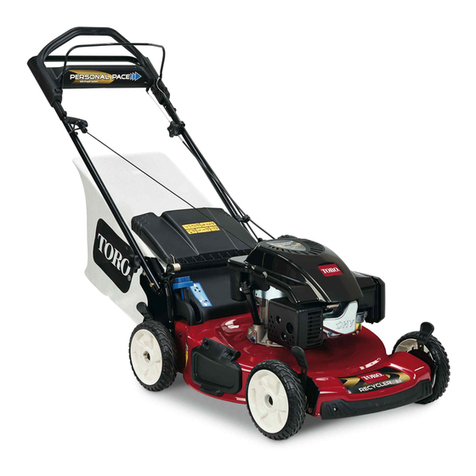
Toro 26638 User manual

'% ,., ,*-#+2
)) (&'0/ %/%.1%$
!
"
-! "',-+.-"(', +.%%2 &"%"+ 0"-!
-! ('-+(%, ' -! )+()+ ., ( -! *.")&'-
/+ %%(0 !"%+' (+ )()% .'&"%"+ 0"-!
-!, "',-+.-"(', -( ., -! %0'&(0+ (%
+ .%-"(', &2 +,-+"- -! ( -! ()+-(+
/+ &(0 0!"% )()% ,)"%%2 !"%+' (+
)-, + '+2
) "' &"' -!- -! ()+-(+ (+ .,+ ",
+,)(',"% (+ "'-, (+ !3+, (.++"' -(
(-!+ )()% (+ -!"+ )+()+-2
!"% &(0"' %02, 0+ ,.,-'-"% ((-0+
' %(' -+(.,+, ( '(- ()+- -! *.")&'-
0!' +((- (+ 0+"' ()' ,'%,
!(+(. !%2 "',)- -! + 0!+ -!
*.")&'- ", -( ., ' +&(/ %% (#-,
0!"! &2 -!+(0 2 -! &!"'
%02, 0+ ,-2 %,,, (+ 2 ,!"%, .+"'
()+-"(' -( )+(-- 2, +(& (+" ' (#-, -!-
&2 -!+(0' +(& -! &!"' +"' ( !+"'
)+(--"(' )+(--"/ %(/, ' ,-2 !%&- ",
/",% ' &2 +*."+ 2 %(% + .%-"(',
-+(% ", !" !%2 %&&%
-(+ .% "' ('-"'+, ,)""%%2 ," ' (+
-!", ).+)(,
.% (.-((+, ('%2 ' ( '(- ,&($ 0!"%
+.%%"'
.% (+ ,-+-"' -! ' "' /+
+&(/ -! ) ( -! .% -'$ (+ )-+(% 0!"%
-! ' "' ", +.''"' (+ 0!' -! ' "' ", !(-
)-+(% ", ,)"%% ( '(- --&)- -( ,-+- -!
' "' .- &(/ -! &!"' 02 +(& -! + (
,)"%% ' /(" +-"' '2 ,(.+ ( " '"-"(' .'-"%
)-+(% /)(+, !/ ",,")-
)% %% .% -'$, ' ('-"'+ ),
,.+%2
)% .%-2 ,"%'+,
(+ .,"' %02, /",.%%2 "',)- -( , -!-
-! %, % (%-, ' .--+ ,,&%2 + '(-
0(+' (+ & )% 0(+' (+ & %,
' (%-, "' ,-, -( )+,+/ %'
' &.%-"4% &!"', -$ + , +(--"'
(' % ' ., (-!+ %, -( +(--
( '(- ()+- -! ' "' "' ('"' ,)
0!+ ' +(., +(' &('(1" .&, '
(%%-
(0 ('%2 "' 2%" !- (+ "' (( +-"""% %" !-
/(" ()+-"' -! *.")&'- "' 0- +,,
0!+ ,"%
%02, ,.+ ( 2(.+ ((-"' (' ,%(),
%$ '/+ +.'
(+ 0!% +(-+2 &!"', &(0 +(,, -!
( ,%(), '/+ .) ' (0'
1+", 1-+& .-"(' 0!' !' "'
"+-"(' (' ,%(),
( '(- &(0 1,,"/%2 ,-) ,%(),
, 1-+& .-"(' 0!' +/+,"' (+ ).%%"'
-! %0'&(0+ -(0+, 2(.
-() -! %, " -! %0'&(0+ !, -(
-"%- (+ -+',)(+--"(' 0!' +(,,"' ,.+, (-!+
-!' +,, ' 0!' -+',)(+-"' -! %0'&(0+ -(
' +(& -! + -( &(0
/+ ()+- -! %0'&(0+ 0"-! -"/
.+, (+ ,!"%, (+ 0"-!(.- ,-2 /", (+
1&)% %-(+, '(+ +,, -!+, "' )%
( '(- !' -! ' "' (/+'(+ ,--"' , (+
(/+,) -! ' "'
",' %% % ' +"/ %.-!, (+
,-+-"' -! ' "'
-+- -! ' "' (+ ,0"-! (' -! &(-(+ +.%%2
(+"' -( "',-+.-"(', ' 0"-! - 0%% 02 +(&
-! %,
( '(- -"%- -! %0'&(0+ 0!' ,-+-"' -!
' "' (+ ,0"-!"' (' -! &(-(+ 1)- " -!
%0'&(0+ !, -( -"%- (+ ,-+-"' ' -!", ,
( '(- -"%- "- &(+ -!' ,(%.-%2 ',,+2 ' %"-
('%2 -! )+- 0!"! ", 02 +(& -! ()+-(+
( '(- ,-+- -! ' "' 0!' ,-'"' "' +('- (
-! ",!+ !.-

!
Do not put h nds or feet ne r or under rot ting
p rts. Keep cle r of the disch rge opening t ll
times.
Never pick up or c rry l wnmower while the
engine is running.
Stop the engine nd disconnect the sp rk plug
wire.
Dbefore cle ring block ges or unclogging chute;
Dbefore checking, cle ning or working on the
l wnmower;
Dfter striking foreign object. Inspect the
l wnmower for d m ge nd m ke rep irs before
rest rting nd oper ting the l wnmower;
Dif l wnmower st rts to vibr te bnorm lly (check
immedi tely).
Stop the engine
Dwhenever you le ve the l wnmower;
Dbefore refuelling.
Reduce the throttle setting during engine shut
down nd, if the engine is provided with shutĆoff
v lve, turn the fuel off t the conclusion of mowing.
Go slow when using tr iling se t.
Keep ll nuts, bolts nd screws tight to be sure
the equipment is in s fe working condition.
Never store the equipment with petrol in the t nk
inside building where fumes m y re ch n open
fl me or sp rk.
Allow the engine to cool before storing in ny
enclosure.
To reduce the fire h z rd, keep the engine,
silencer, b ttery comp rtment nd petrol stor ge re
free of gr ss, le ves, or excessive gre se.
Check the gr ss c tcher frequently for we r or
deterior tion.
Repl ce worn or d m ged p rts for s fety.
If the fuel t nk h s to be dr ined, this should be
done outdoors.
This unit h s n equiv lent continuous AĆweighted
sound pressure t the oper tor e r of: 89 dB(A),
b sed on me surements of identic l m chines per
ANSI B71.5Ć1984 procedures.
This unit h s sound power level of: 100 dB(A)/1 pW,
b sed on me surements of identic l m chines per
Directive 84/538/EEC nd mendments.
This unit h s m ximum h ndĆ rm vibr tion level of
4.6 m/s@, b sed on me surement of identic l
m chines per ISO 5349 procedures.

Safety alert symbol
Read operator’s manual
Rotating blade can cut off
toes or fingers. Stay clear of
Thrown or flying objects––
Whole body exposure
Thrown or flying objects––
Rotary side-mounted mower.
Stay a safe distance
from the mower
Do not open or
remove safety shields
while engine is running
Consult technical
manual for proper
service procedures
Stop engine before
leaving operator
position
To avoid blade failure when
mulching, use blade stiffener
when mower is equipped
with mulching plug
Transmission
Oil
On/Run
Engage
Disengage
Battery charging
condition
Stay a safe distance
from the machine
Safety alert triangle––
symbol within triangle
indicates a hazard
mower blade as long as
engine is running.
Keep deflector shield in
place.

Fast
Slow
Decreasing/increasing
Grease lubrication
point
Engine start
Engine stop
Choke
Primer (start aid)
Neutral
First gear
Second gear
Third gear
Fuel
Cutting element––
basic symbol
Cutting element––
Height adjustment
Pull rope
Push primer
three times
Wheel
Wheel traction
Hourmeter/elapsed
operating hours

Insert key into
ignition switch
Turn key in ignition
switch
Move control
Lower control bar
Raise control bar
Raise/lower control bar
Raise control bar
Properly dispose
of batteries
Lower control bar
Raise control bar
Page Page
Set-Up Instructions 6. . . . . . . . . . . . . . . . . . . . . . . . . . . .
Before Operating 7. . . . . . . . . . . . . . . . . . . . . . . . . . . . . . .
Operating Instructions 9. . . . . . . . . . . . . . . . . . . . . . . . . .
Maintenance 14. . . . . . . . . . . . . . . . . . . . . . . . . . . . . . . . . .
Recommended Maintenance Schedule 14. . . . . . .
Servicing Air Cleaner 14. . . . . . . . . . . . . . . . . . . . . . .
Replacing Spark Plug 15. . . . . . . . . . . . . . . . . . . . . .
Draining Gasoline 15. . . . . . . . . . . . . . . . . . . . . . . . .
Changing Crankcase Oil 15. . . . . . . . . . . . . . . . . . . .
Adjusting Throttle 16. . . . . . . . . . . . . . . . . . . . . . . . . .
Adjusting Traction heel Drive 16. . . . . . . . . . . . . .
Inspecting/Removing/Sharpening Blade 17. . . . . .
Lubrication 18. . . . . . . . . . . . . . . . . . . . . . . . . . . . . . .
Adjusting Blade Brake 18. . . . . . . . . . . . . . . . . . . . . .
Cleaning Blade Brake Clutch Shields 19. . . . . . . . .
Cleaning Mower Housing 20. . . . . . . . . . . . . . . . . . .
Preparing Mower For Storage 20. . . . . . . . . . . . . . .
Optional Equipment 21. . . . . . . . . . . . . . . . . . . . . . . . . . .
Product Identification 21. . . . . . . . . . . . . . . . . . . . . . . . . .
Toro Service Support 21. . . . . . . . . . . . . . . . . . . . . . . . . .
The Toro Starting Guarantee 22. . . . . . . . . . . . . . . . . . . .
Guaranteed To Start Maintenance Record 23. . . . . . . .

INSTALLING HANDLEĊLoosen knobs on
mounting br ckets (Fig. 1).
Position mounting br ckets in vertic l position so
th t holes f ce up.
Slide h ndle ends into holes in mounting br ckets
until h ndle ends re completely se ted in br ckets
(Fig. 1). M ke sure c bles rest on top of mounting
br ckets (Fig. 2).
'%0-#
*")#
+0*/'*% -!(#/
*+
+0.'*% ,+!(#/
811
Rot te h ndle nd br ckets re rw rd until
br ckets fit securely into housing pockets (Fig. 2).
&-+//)# ! )#
'%0-#
809
-!/'+* ! )# #-.&'$/ ! )#
Tighten knobs until edges of slots on top of
mounting br ckets touch.
Use c ble ties to secure c bles to lower ends of
h ndle tubes (Fig. 3). C ble ties should be positioned
25 mm (1") from bend in h ndles. See Figure 3 for
correct pl cement.
+/# M ke sure c bles do not interfere with the
r ising or lowering of disch rge door.
Cut excess length from ends of c ble ties.
'%0-#
)# /'#
810
Pull the st rter rope through the rope guide on
the h ndle (Fig. 4). To m ke the rope e sier to loop,
squeeze the control b r on the h ndle to rele se the
bl de br ke.
+,# %0'"# /-/#- -+,#
M-2882
'%0-#

GB-7
SET-UP INSTRUCTIONS
INSTALL GRASS BAG
1. %-6) (-6',%5+) (225 6/-() &%+ 5%03 %77%',)( 72
&%+ -172 (-6',%5+) 23)1-1+ %1( ,22. &%+ *5%0)
2172 5281()( 3257-21 2* 02817-1+ &5%'.)76 -+
1. Bag door
2. Bag ramp
5. Mounting bracket
6. Bag frame hook
1
4
3
5
2
6
Figure 5
3. Discharge door
4. Bag handle
Note: %.) 685) +5%66 &%+ (225 -6 fully '/26)(
%+%-167 +5%66 &%+ &)*25) -167%//-1+ &%+ 21 02:)5
2. //2: (-6',%5+) (225 72 5)67 21 723 2* &%+ -+
Figure 6
BEFORE OPERATING
FILL CRANKCASE ITH OIL
-// '5%1.'%6) :-7, ! 25 $ 2-/ 817-/ 2-/ /)9)/
5)%',)6 # 0%5. 21 (-367-'. %6 6,2:1 -1 -+85)
",) 0%;-080 '5%1.'%6) '%3%'-7< -6 281')6
/-7)56 2* 2-/ #6) %1< ,-+, 48%/-7< ()7)5+)17 2-/
,%9-1+ 7,) 0)5-'%1 )752/)80 167-787)
=6)59-') '/%66-*-'%7-21 > ! ! ! 25 !
)*25) )%', 86) )1685) 2-/ /)9)/ -6 &)7:))1 %1(
# 0%5.6 -+ (( 2-/ -* /)9)/ -6 /2:
Figure 7
1. Oil fill tube 4. FULL mark3. ADD mark2. Dipstick
3
4
m-3665/284
1
2
1. 26-7-21 02:)5 21 /)9)/ 685*%') %1( '/)%1 %5281(
2-/ (-367-'.
2. )029) (-367-'. &< 527%7-1+ '%3 '2817)5'/2'.:-6)
7851
3. $-3) (-367-'. %1( -16)57 -7 -172 *-//)5 1)'. 27%7)
'%3 7851 ",)1 5)029) (-367-'. %1( ',)'. /)9)/ 2*
2-/ -+ * /)9)/ -6 /2: %(( 21/< )128+, 2-/ 72 5%-6)
/)9)/ 72 # 0%5. 21 (-367-'. DO NOT FILL ABOVE
FULL MARK BECAUSE ENGINE COULD BE
DAMAGED HEN STARTED. POUR OIL SLO LY.
Note: ,)'. 2-/ /)9)/ )%', 7-0) 02:)5 -6 86)( 25
%*7)5 )9)5< ,2856 2* 02:)5 23)5%7-21 1-7-%//<
',%1+) 2-/ %*7)5 7,) *-567 ,2856 2* 23)5%7-21
7,)5)%*7)5 ',%1+) 2-/ %*7)5 )9)5< ,2856 2*
23)5%7-21 )*)5 72 ,%1+-1+ 5%1.'%6) -/
3%+) 25) *5)48)17 2-/ ',%1+)6 %5) 5)48-5)( -1
(867< 25 (-57< '21(-7-216
4. 16)57 (-367-'. -172 *-//)5 1)'. %1( 527%7) '%3
'/2'.:-6) 7851 72 /2'. -7 -1 3/%')

GB-8
BEF RE PERATING
FILL FUEL TANK WITH GAS LINE
DANGER: Gasoline is extremely flammable
and explosive under certain conditions. D
N T SM KE when handling fuel and keep fuel
far away from open flames and sparks. Never
buy more than a 30 day supply of gasoline.
Store it in an approved container. Keep gasoĆ
line out of reach of children.
Refuel outdoors and only when engine is cold.
Do not fill tank full. Fill tank to within 6 to 13
mm (1/4" to 1/2") from top of tank, not into fillĆ
er neck. This space is for expansion of fuel.
Use funnel or spout to prevent spilling. Wipe
up any spilled gas.
WARNING
Note $&$ $"%#- '(&$#!- &$""#' (
)' $ &' !# UNLEADED &)!& &
'$!# # $&$ '$!# %$+& %&$)('
#! '$!# )&#' !#& ,(#' ## !
# %&$"$(' $$ '(&(# - &)# (
)!)% $ $")'($# "& %$'('
'$!# # )' )#! ' #$( *!!
1. !# &$)# )! (# % # &"$*
% &$" (#
Figure 8
1. Fuel tank cap 2. Primer
1
2
m-3665
2. '# )#! '$!# !! )! (# ($ +(# ($
"" ($ # &$" ($% $ (# #$( #($ (
!!& # $ #$( !! (# )!!
3. #'(!! )! (# % # +% )% #- '%!!
'$!#
$&$ !'$ &$""#' (( $&$
(!.&$#($#& )' &)!&!- # !! $&$
'$!# %$+& %&$)(' )&# $%&($# #
'($& ''$#' $&$ (!.&$#($#& !#'
( ## )&# $%&($# # %&*#(' )"/!
*&#' %$'(' &$" $&"# # ( ## )&#
%&$' $ '($&
IMP RTANT: Do not mix oil with the gasoline.
Never use methanol, gasoline containing
methanol, gasohol containing more than 10%
ethanol, premium gasoline or white gas because
engine fuel system damage could result.
Do not use fuel additives other than those
manufactured for fuel stabilization during storage
such as Toro's Stabilizer/Conditioner or a similar
product. Toro's Stabilizer/Conditioner is a
petroleum distillate based conditioner/stabilizer.
Toro does not recommend stabilizers with an
alcohol base such as ethanol, methanol or
isopropyl. Additives should not be used to try to
enhance the power or performance of machine.

!
CHECK IL LEVELĊMaintain oil level between
ADD and FULL range as shown on dipstick (Fig. 7).
BEF RE EACH M WINGĊEnsure self-propelled
drive and control bar function properly. Traction drive
and blade are designed to stop when control bar is
released.
CUTTING AND BAGGINGĊBest results are
achieved when engine is running at maximum speed
and only about 1/3 of the grass blade is cut. If long
grass must be cut, use highest height-of-cut
setting for first mowing. Then recut the grass at a
more normal setting. If too long of grass is cut,
mower may plug and cause engine to stall.
When cutting in dry, dusty conditions move the
throttle to a slower speed to reduce the amount of
dust generated by mower.
SHARP BLADEĊBegin each cutting season with a
sharp blade. Periodically file down nicks.
C NTR LSĊThrottle, ground speed control, and
self-propelled control bar and fingertip starter are on
upper handle (Fig. 9).
+)41'
1/4.& 20''&
*1/33-'
'-(01/0'--'& %/.31/- $#1
+.)'13+0 23#13'1
112
Push spark plug wire onto spark plug (Fig. 10).
Move ground speed control to (NEUTRAL)
position.
Move throttle control to (FAST) position.
Push primer three (3) times (Fig. 8). "#+3 #$/43
36/ 2'%/.&2 $'36''. '#%* 042*
/3' Do not use primer to restart a warm engine
after a short shutdown. However, cool weather may
require priming to be repeated.
+)41'
0#1, 0-4) 6+1'
m-3662
Pull recoil starter out until positive engagement
results; then pull vigorously to start the engine. When
engine starts, regulate engine speed as desired.
TRACTI N PERATI N (Fig. 9)ĊMove ground
speed control to desired setting. Number 1" is slow,
2" is medium, and 3" is a fast walking pace.
Ground speed varies, depending on space between
control bar and handle. Move ground speed control
to when using the mower for trimming and
whenever leaving the mower.
BLADE AND TRACTI N PERATI N
(Fig. 11)ĊMove control bar down to A" and raise to
B" to engage blade. Squeeze control bar against
handle C" to drive. To disengage traction drive but
keep blade engaged, gradually release control bar to
mid position. To self-propel with blade disengaged,
simply squeeze control bar against handle,
eliminating downward movement necessary for blade
engagement.
+)41'
145
0''& 5#1+'2 +& 0/2+3+/.

/4% The drive wheels re equipped with
freewheeling clutches which en ble the mower to be
pulled re rw rd e sier when the wheel drive is
diseng ged. To diseng ge the clutches, mower must
be pushed forw rd t le st 2.5 cm (1") fter wheel
drive oper tion h s stopped.
STOPPING (Fig. 11)ĊRele se control b r to stop
bl de nd tr ction drive. Move ground speed control
to N". To stop engine, move throttle to (OFF).
Pull wire off sp rk plug if mower will be un ttended or
not used.
Stop engine nd w it for ll moving p rts to stop.
INSTALLING BAGĊR ise disch rge door, slide
b g r mp tt ched to b g into disch rge opening,
nd hook b g fr me onto mounting br cket (Fig. 12).
Allow disch rge door to rest on top of b g (Fig. 13).
/4% M ke sure gr ss b g door is &5,,8 closed
g inst gr ss b g before inst lling b g on mower.
REMOVING BAGĊ4/0 %.').% !.$ 7!)4 &/2 !,,
-/6).' 0!243 4/ 34/0 For protection, lw ys keep
h nds nd feet w y from mower housing while
engine is running. R ise disch rge door. While
holding disch rge door up, gr sp h ndle on gr ss
b g nd lift b g off mower. Allow disch rge door to
close.
/4% When removing the gr ss b g, the b g r mp
scoops out ny clippings th t m y be plugging the
disch rge opening. If the disch rge opening rem ins
plugged, pull wire off sp rk plug nd cle r ll
clippings from the mower.
EMPTYING BAGĊGr sp b g h ndle nd re r of
gr ss b g. Tip b g door up nd gr du lly tip b g
forw rd to empty clippings.
!' $//2
!' 2!-0
)3#(!2'% $//2
!' (!.$,%
/5.4).' "2!#+%4
!' &2!-% (//+
775
)'52%
795
)'52%
2!33 #,)00).'3 !.$ /4(%2 /"*%#43 #!. "%
4(2/7. &2/- !. /0%. $)3#(!2'% 45..%,
"*%#43 4(2/7. 7)4( %./5'( &/2#% #/5,$
#!53% 3%2)/53 0%23/.!, ).*528 /2 $%!4( 4/ /09
%2!4/2 /2 "834!.$%2
%6%2 /0%. $//2 /. $)3#(!2'% 45..%, 7(%.
%.').% )3 25..).' 5.,%33 4(% '2!33 "!' )3 3%9
#52%,8 ).34!,,%$
7/2. '2!33 "!' #/5,$ !,,/7 3-!,, 34/.%3
!.$ /4(%2 3)-),!2 $%"2)3 4/ "% 4(2/7. ). /0%29
!4/23 /2 "834!.$%23 $)2%#4)/.
(2/7. /"*%#43 #!. #!53% 3%2)/53 0%23/.!,
).*528 /2 $%!4( 4/ /0%2!4/2 /2 "834!.$%23
(%#+ 4(% '2!33 "!' &2%15%.4,8 & )4 )3 $!-9
!'%$ ).34!,, ! .%7 '%.5).% 2%0,!#%9
-%.4 "!'
Three numbers c st into the housing represent the
height-of-cut settings. The di mond between e ch
number represents 13 mm (1/2") increment.
Stop the engine nd w it for ll moving p rts to
stop. Pull wire off sp rk plug.

! !"!
&,645+0) *'+)*51(%65 .'7'34 %16.& $3+0)
*#0&4 +051 %105#%5 8+5* /17+0) $.#&'
105#%5 8+5* $.#&' %16.& %#64' 4'3+164 2'3:
410#. +0,639
1 015 #&,645 5*' *'+)*51(%65 4'55+0)4
8*'0 '0)+0' +4 3600+0) #0& $.#&' +4 315#5+0)
1 015 265 (+0)'34 60&'3 *164+0) 51 .+(5 /18:
'3 8*'0 #&,645+0) *'+)*51(%65 .'7'34
For asi r adjustm nt, lift housing up so wh l is
off ground. 1 015 2.#%' *#0&4 60&'3 &'%- 51 .+(5
*164+0) Squ z adjusting l v r toward wh l and
mov to d sir d s tting (Fig. 14). Ensur pin on
adjusting l v r ngag s notch in housing. Adjust all
wh ls to th sam s tting.
15' Front wh ls can b adjust d to 13 mm (1/2").
Mov adjusting l v r past 1" and r l as pin into
notch in housing.
In conditions wh n maximum pow r is r quir d or
wh n cutting in spongy thatch that caus s r ar
wh ls to sink in turf, rais r ar wh l s tting on
incr m nt high r. Mak sur wh l s ttings ar
r turn d to qual s ttings, wh n cutting in normal
conditions, to achi v th b st quality of cut.
+)63'
'+)*5:1(:%65 .'7'3
146
1
♦
2
♦
3
=
=
=
=
=
25 mm (1″)
38 mm
51 mm
64 mm
76 mm
(1-1/2
(2
(2-1/2
(3″)
″)″)
″)
! !
Ch ck th control bar b for ach us to nsur th
Blad Brak Clutch (BBC) syst m is op rating
prop rly.
13/#. 10531. #3 2'3#5+10 !'45
With ngin off, wh l mow r onto a pav d
surfac in a nonĆwindy ar a.
Put all four wh ls in 3" h ight-of-cut position
(Fig. 14).
Put ground sp d s l ctor in (n utral) position.
Tak a half sh t of n wspap r and crumpl it into
a ball small nough to go und r d ck (approx. thr
inch s in diam t r) (Fig. 15).
Plac ball of n wspap r fiv inch s in front of
mow r (Fig. 15).
+)63'
756
%/
Start th ngin .
Push control bar down to low st position (Fig. 16).
+)63'
Lift control bar to th normal blad ngag d"
position (about on inch b low th handl )
(Position A, Fig. 17). Th fan" nois indicat s that
th mow r blad is turning.

Release the control bar (Position B, Fig. 17). A
bang" shoul be hear . The bla e shoul stop
running in three secon s.
1” (2,5 cm)
#"+(
Imme iately push the mower over the newspaper
ball.
Turn off the engine.
Walk aroun the mower to check for the
newspaper ball. If the ball i not go un er the eck,
repeat steps 5-11.
Pull mower away from the newspaper. If the
newspaper ball unravels or is shre e , it in icates
that the bla e has not stoppe as it shoul , resulting
in an unsafe operating con ition. Contact an
Authorize Toro Service Dealer for an inspection at
your earliest convenience. However, to etect BBC
system eterioration !&( it affects normal
operation, we also ask you to perform Special Control
Bar Test B which follows.
' #$ &%*(&$ ( )*
With the engine off, wheel mower onto a pave
surface in a nonĆwin y area.
Put all four wheels in 3" height-of-cut position
(Fig. 14).
Put groun spee selector in (neutral) position.
Take a half sheet of newspaper an crumple it into
a ball small enough to go un er the eck (approx.
three inches in iameter) (Fig. 15).
Place ball of newspaper five inches in front of
mower (Fig. 15).
Start the engine.
Push control bar own to lowest position (Fig. 18,
position B).
#"+(
Bring the control bar up into the mi position
(about 5 inches below the han le cross bar)
(Fig. 19, position C).
#"+(
&* This interme iate position (C) is not the
natural" operating position of the control bar.
However, it has proven to be useful in early etection
of BBC sticking which coul create an unsafe
con ition later in the life of the mower.
Release control bar (Fig. 19, position B).
&* If a lou bang is hear , the control bar has
been raise too high. Repeat steps 7, 8 an 9, but o
not raise the control bar as high as in step 8.
Imme iately push the mower over the newspaper
ball.
Turn off the engine.
Walk aroun the mower to check for the
newspaper ball. If the ball i not go un er the eck,
repeat steps 5-11.
Pull mower away from newspaper. If the
newspaper ball unravels or is shre e , it in icates
the system coul be experiencing wear/ eterioration
which coul result in an unsafe operating con ition.
Use care in operating the mower an BBC system
an contact an Authorize Toro Service Dealer for an
inspection of your mower at your earliest
convenience. They will ensure that appropriate
corrective measures are performe an your mower
is restore to proper operating con ition.

POTENTIAL HAZARD
•If the Blade Brake Clutch system is
inoperative, blade will continue to rotate
when control bar is released. Contact with
blade could occur.
WHAT CAN HAPPEN
•Blade contact can cause serious personal
injury or death.
HOW TO AVOID THE HAZARD
•Never use a BBC equipped power mower
with an inoperative safety system.
•Return your lawn mower to your dealer for
repair if a safety system fails to operate
properly.
Whenever performing operations
such as cleaning the mower, first stop the engine and
disconnect the spark plug wire. Remove key from
switch on electric start model. As with any
lawnmower, regardless of the safety features and
blade stopping devices used, operators should keep
all body parts away from the cutting blade area
whenever the mower's engine is running, and keep
bystanders away as well.
Should you require further information or assistance,
feel free to contact us at:
he oro Company
Attn: Consumer Service Department
8111 Lyndale Avenue South
Bloomington, MN 55420-1196
(612) 887-8255
he grass bag can be used for an additional test to
check the Blade Brake Clutch mechanism.
Install the empty grass bag on the discharge
tunnel.
Start the engine.
Push the control bar (Fig. 18) down to the lowest
position.
Lift the control bar to the normal blade engaged
position, about one inch below the handle. he bag
should begin to inflate which indicates the blade is
engaged and rotating.
Release control bar. If the bag does not
immediately deflate, it indicates the blade is still
rotating. Deterioration of the Blade Brake Clutch
mechanism may have set in, which could result in an
unsafe operating condition. Have mower inspected
by an Authorized ORO Service Dealer.

"# ! " # ! #" "
Service Item Service Operation
After
every
use 5
Hours 25
Hours 50
Hours 100
Hours
Housing Clean built-up grass clippings and dirt. X
Fasteners
Check blade and engine mounting
fasteners frequently. Keep all nuts, bolts
and screws tight to be sure the mower is in
safe working condition.
X
Lubrication Grease rear grease fittings. X
Spark Plug Inspect every 25 hours and replace if
necessary. Replace after every 100
operating hours or once a season. X
Engine Oil
Drain and refill engine crankcase with
fresh oil after first 5hours of operation.
Thereafter, change every 50 hours.
Change oil every 25 hours when
operating under heavy load or in high
temperatures.
X
Blade Sharpen or replace; maintain more
frequently if edge is dulled quickly in rough
or sandy conditions. X
Blade Brake
Check stopping time every 50 hours or at
start of each mowing season. Blade must
stop within three seconds of releasing bail;
if not see your Authorized Toro Service
Dealer for repair.
X
Fuel System Check for leakage and/or deterioration of
fuel hose. Replace if necessary. X
Air Filters Clean or replace each mowing season or
every 100 hours. Clean more frequently
if operating conditions are dusty. X
Cooling
System
Clean grass, clippings, debris or dirt that
may clog engine air cooling fins and
starter. Clean more frequently if operated
under dirty or high chaff conditions.
X
"( /#+ #, )( ,*+% *&.! ,)')(
).& #(-&&0 ,-+- -" (!#(
#(-& ,-+-#(! ) (!#( ).& .,
,+#)., #($.+0 -) )*+-)+ )+
0,-(+,
.&& /#+ ) ,*+% *&.! )+ *+ )+'1
#(! (0 '#(-(( )+ $.,-'(-,
& ' " $ &
" # ! $ & !! "
" " $ & # ! $ & !!
#" ! # % % !
" #!"& "& "!
"! $ & "&
" # % ! #
$ "% ! !# $
"

GB-15
MAINTENANCE
Figure 20
1. Knob
2 Cover
3. Foam preĆcleaner
4 Paper cartridge
ÎÎÎÎ
ÎÎÎÎ
ÎÎÎÎ
m-3664
1
2
3
4
3. Lift cover off. Clean cover thoroughly.
4. Carefully remove preĆcleaner. If preĆcleaner is dirty,
carefully wash it in a solution of liquid soap and warm
water. Rinse in clear water. Allow to dry thoroughly
before using.
5. If paper cartridge is dirty, clean the paper filter by
tapping it gently on a flat surface. If very dirty,
replace cartridge.
IMPO TANT: Do not oil pre-cleaner or paper
cartridge. Do not use pressurized air to clean
paper cartridge.
6. Reinstall preĆcleaner over paper cartridge.
Reinstall air cleaner cover and tighten securely in
place with two (2) knobs.
IMPO TANT: Do not operate engine without air
cleaner element otherwise extreme engine wear
and damage will likely result.
EPLACING SPA K PLUG
Use a CHAMPION RC12YC spark plug or equivalent.
Correct air gap is 0.5 mm (0.020"). Remove plug after
every 25 operating hours and check its condition.
1. Stop engine and wait for it to cool. Pull wire off
spark plug (Fig. 10).
2. Clean around spark plug and remove plug from
cylinder head.
IMPO TANT: eplace a cracked, fouled, or dirty
spark plug. Do not sand blast, scrape, or clean
electrodes because engine damage could result
from grit entering cylinder.
3. Set air gap at 0.5 mm (0.020") (Fig. 21). Install
correctly gapped spark plug and gasket seal. Tighten
plug firmly to 19 Nm (14 ft-lb).
Figure 21
.5 mm
(0.020")
D AINING GASOLINE
1. Stop engine and wait for engine to cool. Pull wire
off spark plug (Fig. 10).
Note: Drain gasoline from a cold engine only.
2. Remove cap from fuel tank and use pump-type
syphon to drain fuel into clean gas can.
Note: This is the only procedure recommended for
draining fuel.
CHANGING C ANKCASE OIL
Change oil after the first 5 operating hours and after
every 50 hours thereafter. Since warm oil drains
better and carries more contaminants than cold, run
engine for several minutes before draining oil.
1. Drain gasoline. Refer to Draining Gasoline section.
2. Run engine until it dies. Try starting engine once
more to make sure gas is out of carburetor.
3. Pull wire off spark plug (Fig. 10).
4. Lift discharge door and remove grass bag. Drain
gasoline from fuel tank: refer to Draining Gasoline,
page 15.
5. Remove dipstick from oil fill tube and place a drain
pan next to left side of mower.
6. Tip mower on its left side, allowing oil to drain into
drain pan (Fig. 22).
7. hen oil is drained, return mower to upright
position and add fresh oil to engine. Refer to Fill
Crankcase ith Oil, page 7.

R conn ct spark plug wir .
(&2/$
(* %(** 12"$
m-3663
Throttl control adjustm nt may b r quir d if ngin
do s not start or stop. Wh n v r a n w throttl
control cabl is install d, th throttl must b
adjust d.
Stop ngin and pull wir off spark plug (Fig. 10).
Loos n cabl clamp scr w until throttl cabl
slid s (Fig. 23).
Mov gov rnor control l v r, throttl cabl and
casing in dir ction of arrow as far as possibl
(Fig. 23).
Mov throttl control to (FAST position).
Tight n cabl clamp scr w to lock adjustm nt in
plac .
!"*$ #*!+. 0#/$4
-3$/,-/ #-,1/-*
*$3$/
'/-11*$ #!"*$
!0(,&
(&2/$
m-3638
If mow r do s not s lf-prop l or has a t nd ncy to
cr p forward wh n driv is not ngag d, an
adjustm nt to th wh l traction control cabl is
n c ssary.
Stop ngin and pull wir off spark plug (Fig. 10).
Lift control bar until som r sistanc is f lt. Control
bar should b 38 mm (1!2") from handl wh n
prop rly adjust d (Fig. 24).
(&2/$
149
38 mm
(1-1/2")
To adjust wh l driv cabl , rotat knob und r l ft
front of control pan l (Fig. 25). Rotat knob in positiv
(+) dir ction to incr as distanc b tw n control
bar and handl . Turn knob in n gativ (-) dir ction
to d cr as distanc b tw n control bar and
handl .
(&2/$
*!01(# ),-"
mĆ119
R p at st ps 2 and 3 until prop rly adjust d.

!
top engine and pull wire off spark plug (Fig. 10).
Drain gasoline from fuel tank; refer to Draining
Gasoline, page 15.
Tip mower on its left side. Avoid rotating blade as
starting problems may result.
IN PECTING BLADEĊCarefully examine blade for
sharpness and wear, especially where flat and curved
parts meet (Fig. 26A). ince sand and abrasive
material can wear away the metal that connects the
flat and curved parts of the blade, check blade before
using the mower. If a slot or wear is noticed, (Fig. 26B
& C), replace blade with a new TORO blade. Refer to
step 5.
15' For optimum performance, install a new TORO
blade before cutting season begins. During the year,
file down small nicks to maintain the cutting edge.
+)63'
2494
1
A
B
C
1
1
2
3
4
#+.
.#5 2#35 1( $.#&'
"'#3
.15 (13/'&
REMOVING BLADEĊGrasp end of blade using a
rag or thickly padded glove. Remove blade nuts,
anti-scalp cup, blade, blade spacer and rotating
screen (Fig. 27).
+)63'
.#&' 065
05+4%#.2 %62
.#&'
.#&' 42#%'3
15#5+0) 4%3''0
152
8130 13 &#/#)'& $.#&' %16.& $3'#- #0&
# 2+'%' 1( $.#&' %16.& $' 5*3180 +051 12'3<
#5134 13 $:45#0&'34 #3'#
5*3180 2+'%' 1( $.#&' %16.& %#64' 4'3+<
164 2'3410#. +0,63: 13 &'#5* 51 12'3#513 13
$:45#0&'34
042'%5 $.#&' 2'3+1&+%#..: (13 8'#3 13 &#/<
#)'
'2.#%' # 8130 13 &#/#)'& $.#&'
HARPENING BLADEĊUsing a file, sharpen top
side of blade and maintain original cutting angle
(Fig. 28). The blade remains balanced if the same
amount of material is removed from both cutting
edges.
+)63'
2495
1
*#32'0 #5 5*+4 #0).' 10.:
*'%- $#.#0%' 1( $.#&' $: 2655+0) +5
10 # $.#&' $#.#0%'3 0 +0'92'04+7' $#.#0%'3 %#0
$' 263%*#4'& #5 # *#3&8#3' 4513' $#.#0%'&
$.#&' 45#:4 +0 # *13+;105#. 214+5+10 #0& #0
60$#.#0%'& $.#&' 4'55.'4 51 5*' *'#7: 4+&' (
$.#&' +4 015 $#.#0%'& (+.' /13' /'5#. 1(( %655+0)
'&)' 10 *'#7: '0& 1( $.#&'
Install rotating screen (outside flange pointing
away from housing), blade spacer, sharp, balanced
blade and anti-scalp cup with blade nuts. ail part of
blade must point toward housing to ensure correct
installation. Tighten the blade nuts to 20-37 Nm
(15-27 ft-lb).

!
"!
After every 25 operating hours or when season ends,
front and rear wheels must be lubri ated.
Apply two or three drops of light oil on inside and
outside of all wheel bolts. Spin wheels to distribute oil
into bushings. Wipe up ex ess oil.
Move rear wheel height-of- ut levers to 2"
setting. Wipe grease fittings with lean rag (Fig. 29).
Install grease gun onto fitting and gently apply two or
three pumps of #2 Multi-Purpose Lithium Base
Grease.
.%#/% &)00)+'
)'1.%
%#. 2(%%*
830
" !
Blade brake adjustment may be ne essary if the
quality of ut deteriorates, the bagging ability
degrades, or the engine rpm is audibly faster than
the blade rpm when utting grass.
Stop engine and pull wire off spark plug (Fig. 10).
Remove (2) s rews se uring s reen panel to top
of mower housing (Fig. 30). Remove panel.
$.%%+ -#+%*
)'1.%
$.%2/
300
Move ontrol bar down and lift up against handle.
With ontrol bar against handle, measure the spring
length (L) at the front of the spring as shown in
Figure 31.
-.)+'
)'1.%
*#/0)$ &)00)+'
156
If spring dimension is greater than 32 mm (1!/4")
or less than 25 mm (1"), an adjustment is needed.
To adjust, rotate plasti fitting on blade brake
able (Fig. 31) until spring dimension is as near as
possible to but not less than 25 mm (1"). (See
following note.)
,0% If the spring annot be adjusted to less than
32 mm (1!/4") before the end of the plasti fitting is
rea hed, the lut h belt is worn out and should be
repla ed. After repla ing belt, adjust able as
explained in the above pro edure.
Reinstall s reen panel.

$! ' ! ,&! '/.$ -$%!' ) .$! ,!
!$%) .$! +)!' -,!!) -$*/' ! '!)!
+!,%* %''2 . .$! !) *" !$ (*1%)# -!-*) .
(%)%(/( .* !)-/,! !-. +!,"*,()! ) .* +,!0!).
+,.- !#, .%*)
'"( "$%(! ("' +""(
.*+ !)#%)! ) +/'' 1%,! *"" -+,& +'/# %#
!(*0! .1* (( !2 -!'".++%)# -,!1-
-!/,%)# +)!' -,!!) .* (*1!, !& ) ,!(*0!
+)!' -,!!) %#
+""( *("'
%#.+"
+"/,
!(*0! .$! 0!,.%' +)!' %) ",*). *" .$!
.,)-(%--%*) 2 +/''%)# -.,%#$. /+ %#
"+-% ' *("'
%#.+"
!(*0! )2 !,%- .$. (2 $0! /(/'.! %)
,! !$%) +)!' %#
!%)-.'' 0!,.%' +)!' !/,! +)!' -,!!) .*
(*1!, !& 1%.$ .1* (( !2 -!'".++%)#
-,!1-
!%)-.'' -+,& +'/# 1%,!
'"(%(# '!" +&" '.- $ $%"'!
.*+ !)#%)! ) +/'' 1%,! *"" -+,& +'/# %#
,%) #-*'%)! ",*( "/!' .)& ,!"!, .* ,%)%)#
-*'%)! +#!
%+ (*1!, *) %.- '!". -% ! %#
!(*0! .1* ' ! )/.- ).%-'+ /+ ' !
' ! -+!, ,*..%)# -,!!) ) "*/, *'.- -!/,%)#
-$%!' .* (*1!, !& %#
%#.+"
'!" (.-,
(-%, '* .*
'!"
,$%"'!
,/-$ *, -,+! !,%- ",*( %)-% ! *" -$%!'
!%)-.'' -$%!' /-%)# *'.- ,*..%)#
-,!!) */.-% ! *" "')#! +*%).%)# 12 ",*(
$*/-%)# ' ! -+!, ' ! ).%-'+ /+ )
' ! )/.- %' +,. *" ' ! (/-. +*%). .*1,
.*+ *" (*1!, $*/-%)# %#$.!) ' ! )/.- .*
( ".'
'!" (.-
(-%, '* .*
'!"
'!" ,* "+
)--%(# , +""(
%#.+"
!%)-.'' -+,& +'/# 1%,!

To ensure best performance, keep underside of
mower housing and inside of discharge area clean.
!-&')% $.&*#
Whenever the underside of the mower requires
cleaning, follow this procedure for washing debris out
from underside of deck.
Position mower on a flat concrete or asphalt
surface near a garden hose.
Start the engine.
Engage the blade.
Hold the running garden hose at handle level and
direct water to flow on ground just in front of right
rear tire (Fig. 36). The rotating blade will draw water
under the housing and wash out clippings. Let the
water run for a few minutes or until you no longer see
clippings being washed out from under housing.
Disengage the blade.
Stop the engine.
Turn off the garden hose.
Restart mower and let it run for a few minutes to
dry out moisture on the mower and its components.
While the engine is running, engage and disengage
the blade and traction drive several times to dry them
out.
'%/,$
'%&. ,$!, 0&$$(
10931
",!+')% $.&*#
Stop engine and pull wire off spark plug (Fig. 10).
Drain gasoline from fuel tank: refer to Draining
Gasoline, page 15.
Tip mower on its left side (Fig. 37).
295
'%/,$
Use a hard wood scraper to remove dirt and grass
clippings that stick to housing. Avoid burrs and sharp
edges.
Turn mower upright.
Clean discharge door and hinges of grass or
debris that may impair operation of door.
Refill engine with gas.
Reinstall spark plug wire.
For long term storage, it is recommended that
gasoline be drained from fuel tank or use a fuel
additive before storing. To drain gasoline, refer to
Draining Gasoline, page 15. After fuel is drained, start
engine and let it idle until all fuel is consumed and
engine stops. If gasoline is not drained, gum-like
varnish deposits will form and cause poor engine
operation or even starting problems.
Fuel can be left in gas tank only if a fuel additive,
such as Toro's Stabilizer/Conditioner, is added to
gasoline and run through engine before storing.
Toro's Stabilizer/Conditioner is a petroleum distillate
based conditioner/stabilizer. Toro does not
recommend stabilizers with an alcohol base, such as
ethanol, methanol or isopropyl. Use fuel additive in
recommended quantities as specified on container.
Under normal conditions, fuel additives remain
effective in fuel for 6Ć8 months.
Drain oil: refer to Changing Crankcase il,
page 15. After oil is drained, do not fill crankcase with
oil until the following steps (3-10) are completed.
Remove spark plug and pour 30 ml
(2 tablespoons) of SAE 30 oil into hole in cylinder.
Pull starter rope slowly to coat inside of cylinder.
Install spark plug and tighten to 20 Nm (15 ft-lb).
Clean mower housing; refer to Cleaning Mower
Housing, page 20.
Check condition of blade; refer to
Inspecting/Removing/Sharpening Blade, page 17.
Other Toro Lawn Mower manuals

Toro
Toro TurfMaster 22235 User manual

Toro
Toro 21768 User manual

Toro
Toro Reelmaster 335-D User manual

Toro
Toro TimeCutter HD MyRide 75211 User manual

Toro
Toro ProLine 30135 User manual

Toro
Toro REELMASTER 6700 D User manual

Toro
Toro Proline 30187 User manual

Toro
Toro GrandStand 74536 Manual

Toro
Toro TurfMaster 22205TE User manual

Toro
Toro 4381 User manual

Toro
Toro eSuper Recycler eC53AST User manual

Toro
Toro TimeCutter MX 4275T User manual

Toro
Toro Super Recycler User manual

Toro
Toro 412110343 User manual

Toro
Toro Groundsmaster 3400 User manual

Toro
Toro TimeCutter SW Series Manual

Toro
Toro 4384 User manual

Toro
Toro Recycler 20779 User manual

Toro
Toro 30252 User manual

Toro
Toro Proline 30138 User manual