Toro 30069 User manual

FormNo.3368-897RevB
CommercialWalk-Behind
TractionUnit
18HPPistol-GripHydroDrive
ModelNo.30069—SerialNo.311000001andUp
ToregisteryourproductordownloadanOperator'sManualorPartsCatalogatnocharge,gotowww.Toro.com.OriginalInstructions(EN)

ThisproductcomplieswithallrelevantEuropean
directives,fordetailspleaseseetheseparateproduct
specicDeclarationofConformity(DOC)sheet.
Introduction
Thisrotary-blade,lawnmowerisintendedtobeused
byresidentialhomeownersorprofessional,hired
operators.Itisdesignedprimarilyforcuttinggrasson
well-maintainedlawnsonresidentialorcommercial
properties.Itisnotdesignedforcuttingbrushorfor
agriculturaluses.
Readthisinformationcarefullytolearnhowtooperate
andmaintainyourproductproperlyandtoavoidinjury
andproductdamage.Thismanualshouldbeconsidered
aspartofthemachine,asitcontains,safety,operational
andmaintenanceinformation.Themowerisaprecision
builtmachinedesignedsolelyforcuttinggrassand
similarlowlyinggroundvegetationwithinthelimitations
statedinthismanual.Youareresponsibleforoperating
theproductproperlyandsafely.
YoumaycontactTorodirectlyforproductand
accessoryinformation,helpndingadealer,orto
registeryourproductatToroCommercialProducts
ServiceDepartmentSpellbrook,BishopsStortford,
CM234BU,England,+44(0)1279603019,Email:
uk.service@toro.com.
Wheneveryouneedservice,genuineToroparts,or
additionalinformation,contactanAuthorizedService
DealerorToroCustomerServiceandhavethemodel
andserialnumbersofyourproductready.Figure1and
Figure2identifythelocationofthemodelandserial
numbersontheproduct.Writethenumbersinthe
spaceprovided.
Figure1
1.Modelandserialnumberlocation
ModelNo.
SerialNo.
Figure2
1.Modelandserialnumberlocation
ModelNo.
SerialNo.
Thismanualidentiespotentialhazardsandhassafety
messagesidentiedbythesafetyalertsymbol(Figure3),
whichsignalsahazardthatmaycauseseriousinjury
ordeathifyoudonotfollowtherecommended
precautions.
Figure3
1.Safetyalertsymbol
Thismanualuses2otherwordstohighlightinformation.
Importantcallsattentiontospecialmechanical
informationandNoteemphasizesgeneralinformation
worthyofspecialattention.
©2012—TheToro®Company
8111LyndaleAvenueSouth
Bloomington,MN554202
Contactusatwww.Toro.com.
PrintedintheUSA.
AllRightsReserved

Contents
Introduction.................................................................2
Safety...........................................................................4
GeneralLawnMowerSafety.................................4
SoundPressureforthe32RD,36RDand48
RD...................................................................6
SoundPowerforthe32RD,36RDand48
RD...................................................................6
VibrationLevelforthe32RD...............................6
VibrationLevelforthe36RD...............................6
VibrationLevelforthe48RD...............................6
SlopeIndicator.....................................................7
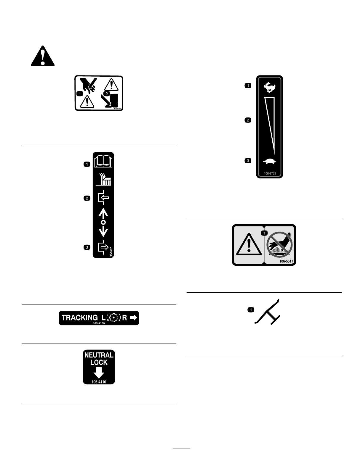
SafetyandInstructionalDecals.............................8
Setup.........................................................................10
1CheckingtheFluidsandTyrePressure..............10
2ReadingtheManualandViewingthe
OperatorTrainingMaterial.............................10
ProductOverview......................................................11
Controls.............................................................11
Specications.....................................................12
Attachments/Acessories....................................12
Operation...................................................................13
AddingFuel.......................................................13
ThinkSafetyFirst...............................................14
OperatingtheParkingBrake...............................14
StartingandStoppingtheEngine........................14
OperatingtheNeutralLocks...............................15
OperatingtheMowerBladeControlKnob
(PTO)............................................................16
TheSafetyInterlockSystem................................16
DrivingtheMachineForwardand
Backward.......................................................17
BringingtheMachinetoNeutralPosition............17
StoppingtheMachine.........................................17
PushingtheMachinebyHand.............................18
TransportingMachines.......................................18
AdjustingtheHeight-of-Cut...............................18
AdjustingtheCasterPosition..............................19
AdjustingtheHandleHeight..............................20
HeightofCutChart............................................21
Maintenance...............................................................22
RecommendedMaintenanceSchedule(s)................22
Lubrication.............................................................22
HowtoGrease...................................................23
LubricatingtheCasterandWheel
Bearings.........................................................23
GreasingtheMowerBeltIdler............................23
GreasingthePumpControlandBell
Crank.............................................................23
EngineMaintenance...............................................24
ServicingtheAirCleaner....................................24
ServicingtheEngineOil.....................................24
ServicingtheSparkPlugs....................................26
FuelSystemMaintenance.......................................27
ServicingtheFuelTank......................................27
ServicingtheFuelFilter......................................28
DriveSystemMaintenance.....................................29
AdjustingtheSpeedControlLinkage..................29
AdjustingtheNeutralControlLinkages..............29
AdjustingtheHydroControlLinkages................30
AdjustingtheControlRod..................................32
AdjustingtheTracking.......................................33
AdjustingtheSpringAnchorLinks.....................33
CheckingtheTyrePressure.................................33
CoolingSystemMaintenance..................................34
CleaningtheAirIntakeScreen............................34
BrakeMaintenance.................................................34
ServicingtheBrake.............................................34
BeltMaintenance....................................................35
CheckingtheBelts..............................................35
ReplacingtheMowerBelt...................................35
AdjustingtheMowerBeltTension......................36
HydraulicSystemMaintenance...............................38
ServicingtheHydraulicSystem...........................38
MowerDeckMaintenance......................................41
ServicingtheCuttingBlades...............................41
AdjustingtheBladeBrake...................................42
Storage.......................................................................43
Troubleshooting.........................................................45
Schematics.................................................................47
3

Safety
Improperlyusingormaintainingthismowercan
resultininjury.Toreducethepotentialforinjury,
complywiththesesafetyinstructions.
Torodesignedandtestedthismowerforreasonablysafe
service;however,failuretocomplywiththefollowing
instructionsmayresultinpersonalinjury.
Toensuremaximumsafety,bestperformance,and
togainknowledgeoftheproduct,itisessential
thatyouandanyotheroperatorofthemowerread
andunderstandthecontentsofthismanualbefore
theengineiseverstarted.Payparticularattention
tothesafetyalertsymbol(Figure3)whichmeans
Caution,Warning,orDanger—“personalsafety
instruction.”Readandunderstandtheinstruction
becauseithastodowithsafety.Failuretocomply
withtheinstructionmayresultinpersonalinjury.
GeneralLawnMowerSafety
ThefollowinginstructionshavebeenadaptedfromEN
836.
Thiscuttingmachineiscapableofamputatinghands
andfeetandthrowingobjects.Failuretoobservethe
followingsafetyinstructionscouldresultinserious
injuryordeath.
Training
•Readtheinstructionscarefully.Befamiliarwiththe
controlsandtheproperuseoftheequipment.
•Neverallowchildrenorpeopleunfamiliarwiththese
instructionstousethemower.Localregulationscan
restricttheageoftheoperator.
•Keepinmindthattheoperatororuserisresponsible
foraccidentsorhazardsoccurringtootherpeopleor
theirproperty.
•Understandexplanationsforallpictogramsusedon
themowerorintheinstructions.
Gasoline
WARNING-Gasolineishighlyammable.Takethe
followingprecautions.
•Storefuelincontainersspecicallydesignedforthis
purpose.
•Refueloutdoorsonlyanddonotsmokewhile
refueling.
•Addfuelbeforestartingtheengine.Neverremove
thecapofthefueltankoraddgasolinewhilethe
engineisrunningorwhentheengineishot.
•Ifgasolineisspilled,donotattempttostartthe
enginebutmovethemowerawayfromtheareaof
spillageandavoidcreatinganysourceofignition
untilgasolinevaporshavedissipated.
•Replaceallfueltankandcontainercapssecurely.
Preparation
•Whilemowing,alwayswearsubstantialfootwearand
longtrousers.Donotoperatetheequipmentwhen
barefootorwearingopensandals.
•Thoroughlyinspecttheareawheretheequipmentis
tobeusedandremoveallstones,sticks,wires,bones
andotherforeignobjects.
•Beforeusing,alwaysvisuallyinspecttoseethat
guards,andsafetydevices,suchasdeectorsarein
placeandworkingcorrectly.
•Beforeusing,alwaysvisuallyinspecttoseethatthe
blades,bladeboltsandcutterassemblyarenotworn
ordamaged.Replacewornordamagedbladesand
boltsinsetstopreservebalance.
Starting
•Disengageallbladeanddriveclutchesandplaceinto
neutralbeforestartingtheengine.
•Donottiltmowerwhenstartingtheengineor
switchingonthemotor,unlessthemowerhastobe
tiltedforstarting.Inthiscase,donottiltitmorethan
absolutelynecessaryandliftonlythepart,whichis
awayfromtheoperator.
•Starttheengineorswitchonthemotorcarefully
accordingtoinstructionsandwithfeetwellaway
fromtheblade(s).
Operation
•Lightningcancausesevereinjuryordeath.If
lightningisseenorthunderisheardinthearea,do
notoperatethemachine;seekshelter.
•Nevermowwhilepeople,especiallychildren,orpets
arenearby.
•Mowonlyindaylightoringoodarticiallight.
•Avoidoperatingthelawnmowerinwetgrass,where
feasible.
•Stayalertforholesintheterrainandotherhidden
hazards.
•Neverdirectdischargeofmaterialtowards
bystanders.
•Donotputhandsorfeetnearorunderrotatingparts.
4

•Neverpickuporcarryalawnmowerwhilethe
engineisrunning.
•Useextremecautionwhenreversingorpullinga
pedestriancontrolledlawnmowertowardsyou.
•Walk,neverrun.
•Slopes:
–Donotmowexcessivelysteepslopes.
–Exerciseextremecautionwhenonslopes.
–Mowacrossthefaceofslopes,neverupand
downandexerciseextremecautionwhen
changingdirectiononslopes.
–Alwaysbesureofyourfootingonslopes.
•Neveroperatethelawnmowerwithdamagedguards,
orwithoutsafetydevices,forexampledeectors
and/orgrasscatchers,inplace.
•Uselowthrottlesettingswhenengagingthe
traction-clutch,especiallyinhighgears.Reduce
speedonslopesandinsharpturnstoprevent
overturningorlossofcontrol.
•Stopthebladeifthelawnmowerhastobetiltedfor
transportationwhencrossingsurfacesotherthan
grassandwhentransportingthelawnmowertoand
fromtheareatobemowed.
•Donotoperatetheengineinaconnedspacewhere
dangerouscarbonmonoxidefumescancollect.
•Stoptheengineandwhereakeyisttedremovethe
key,makesurethatallmovingpartshavecometoa
completestop:
–wheneveryouleavethelawnmower.
–beforerefueling.
–beforeremovingthegrasscatcher.
–beforemakingheightadjustmentunless
adjustmentcanbemadefromtheoperator's
position.
•Stoptheengineandwhereakeyisttedremovethe
key,makesurethatallmovingpartshavecometoa
completestop,anddisconnectthesparkplugwire:
–beforeclearingblockagesoruncloggingchute.
–beforechecking,cleaningorworkingonthelawn
mower.
–afterstrikingaforeignobject,inspectthelawn
mowerfordamageandmakerepairsbefore
restartingandoperatingthelawnmower.
–iflawnmowerstartstovibrateabnormally(check
immediately).
•Reducethethrottlesettingduringengineshutdown
and,iftheengineisprovidedwithashut-offvalve,
turnthefueloffattheconclusionofmowing.
•Usecarewhenusingsulkies,and
–useonlyapproveddrawbarhitchpoints.
–limitloadstothoseyoucansafelycontrol.
–donotturnsharply:usecarewhenreversing.
–donotcarrypassengers.
•Watchoutfortrafcwhencrossingornearroadways.
•Beforeleavingtheoperator'sposition
–disengagethepowertake-offandlowerthe
attachments.
–placeintoneutralandsettheparkingbrake.
–stoptheengineandremovethekey.
MaintenanceandStorage
•Keepallnuts,boltsandscrewstighttobesurethe
equipmentisinsafeworkingcondition.
•Donotusepressurecleaningequipmentonmachine.
•Neverstoretheequipmentwithgasolineinthetank
andinsideabuildingwherefumescanreachanopen
ameorspark.
•Allowtheenginetocoolbeforestoringinany
enclosure.
•Toreducetherehazard,keeptheengine,silencer,
batterycompartmentandgasolinestoragearefreeof
grass,leaves,orexcessivegrease.
•Checkthedischargeguardfrequentlyandreplace
withmanufacturer'srecommendedparts,when
necessary.
•Replacewornordamagedpartsforsafety.
•Replacefaultysilencers.
•Ifthefueltankhastobedrained,dothisout-doors.
•Donotchangetheenginegovernorsettingsor
overspeedtheengine.Operatinganengineat
excessivespeedcanincreasethehazardofpersonal
injury.
•Onmultibladedlawnmowers,takecareasrotating
oneblademaycauseotherstorotate.
•Becarefulduringadjustmentofthelawnmowerto
prevententrapmentofthengersbetweenmoving
bladesandxedpartsofthelawnmower.
•Toensurethebestperformanceandsafety,
purchaseonlygenuineTororeplacementparts
andaccessories.Donotuse
will t
partsand
accessories;theymaycauseasafetyhazard.
5

SoundPressureforthe32RD,
36RDand48RD
The32RDhasasoundpressurelevelattheoperator’s
earof85dBA,whichincludesanUncertaintyValue(K)
of1dBA.
The36RDhasasoundpressurelevelattheoperator’s
earof86dBA,whichincludesanUncertaintyValue(K)
of1dBA.
The48RDhasasoundpressurelevelattheoperator’s
earof89dBA,whichincludesanUncertaintyValue(K)
of1dBA.
Thesoundpressurelevelwasdeterminedaccordingto
theproceduresoutlinedinEN836.
SoundPowerforthe32RD,36
RDand48RD
The32RDand36RDhasaguaranteedsoundpower
levelof100dBA,whichincludesanUncertaintyValue
(K)of1dBA.
The48RDhasaguaranteedsoundpowerlevelof105
dBA,whichincludesanUncertaintyValue(K)of1dBA.
Thesoundpowerlevelwasdeterminedaccordingtothe
proceduresoutlinedinISO11094.
VibrationLevelforthe32RD
Hand-Arm
Measuredvibrationlevelforrighthand=1.0m/s2
Measuredvibrationlevelforlefthand=1.3m/s2
UncertaintyValue(K)=0.7m/s2
Measuredvaluesweredeterminedaccordingtothe
proceduresoutlinedinEN836.
VibrationLevelforthe36RD
Hand-Arm
Measuredvibrationlevelforrighthand=1.5m/s2
Measuredvibrationlevelforlefthand=2.0m/s2
UncertaintyValue(K)=1.0m/s2
Measuredvaluesweredeterminedaccordingtothe
proceduresoutlinedinEN836.
VibrationLevelforthe48RD
Hand-Arm
Measuredvibrationlevelforrighthand=2.5m/s2
Measuredvibrationlevelforlefthand=3.0m/s2
UncertaintyValue(K)=1.5m/s2
Measuredvaluesweredeterminedaccordingtothe
proceduresoutlinedinEN836.
6

SlopeIndicator
G01 1841
Figure4
Thispagemaybecopiedforpersonaluse.
1.Themaximumslopeyoucansafelyoperatethemachineonis20degrees.Usetheslopecharttodeterminethedegreeofslope
ofhillsbeforeoperating.Donotoperatethismachineonaslopegreaterthan20degrees.Foldalongtheappropriateline
tomatchtherecommendedslope.
2.Alignthisedgewithaverticalsurface,atree,building,fencepole,etc.
3.Exampleofhowtocompareslopewithfoldededge.
7

SafetyandInstructional
Decals
Safetydecalsandinstructionsareeasilyvisibletotheoperatorandarelocatednearanyareaof
potentialdanger.Keepsafetysignsclearandvisible,replaceanydecalthatisdamagedorlost.
40-13–010
1.Cuttinghazardofhand
2.Cuttinghazardoffoot
95-5537
1.ReadtheOperator's
Manualforinstructionson
operatingthecuttingblade
3.Pushforwardtoengage
2.Pullbacktodisengage
105-4109
105-4110
106-2733
1.Fast3.Slow
2.Continuousvariable
setting
106-5517
1.Warning–DoNottouchthehotsurface.
Manufacturer'sMark
1.Indicatesthebladeisidentiedasapartfromtheoriginal
machinemanufacturer.
8

115-1039
1.Parking
brake—disengaged
2.Parkingbrake—engaged
115-4212
1.Hydraulicoillevel3.Warning—donottouchthe
hotsurface.
2.ReadtheOperator's
Manual.
119-6672
1.Forward10.Warning—readtheOperator'sManual.
2.Neutral11.Warning—donotoperatethismachineunlessyouaretrained.
3.Reverse12.Thrownobjecthazard—keepdeectorinplace.
4.ToturnthemachinerightengageNeutralontherighthandle
whilethelefthandleisintheForwardposition.
13.Thrownobjecthazard—keepbystandersasafedistancefrom
themachine.
5.ToturnthemachineleftengageNeutralonthelefthandle
whiletherighthandleisintheForwardposition.
14.Warning—wearearprotection.
6.Fast15.Warning—stoptheengineandremovethesparkplugwire
beforeperforminganymaintenanceonthemachine.
7.Continuousvariablesetting16.Warning—stoptheenginebeforeleavingthemachine.
8.Slow17.Cutting,dismembermenthazardofhand—stayawayfrom
movingparts,keepallguardsandshieldsinplace.
9.Neutral
9

Setup
LooseParts
Usethechartbelowtoverifythatallpartshavebeenshipped.
ProcedureDescriptionQty.Use
1Nopartsrequired–Checktheuidsandtyrepressure.
Operator'sManual1
EngineOperator'sManual1
PartsCatalog1
Operatortrainingmaterial1
RegistrationCard1
2
Oildrainhose1
ReadtheOperator'sManualandwatch
theoperatortrainingmaterialbefore
operatingthemachine.
Note:Determinetheleftandrightsidesofthemachinefromthenormaloperatingposition.
1
CheckingtheFluidsandTyre
Pressure
NoPartsRequired
Procedure
•Beforeyoustarttheengineandusethemachine,
checktheoillevelintheenginecrankcase;referto
CheckingtheEngineOilLevel.
•Checkthegreaseforthemowerandmowerdeck.
•Checkthetyrepressure;refertoCheckingthetyre
Pressure.
Note:Thecuttingbladesaresettoa2inch(51mm)
height-of-cutatinitialpurchase.TheAxlepositionis
B,with2spacesbelowthecastersand4spacesbelow
thespindle.
2
ReadingtheManualand
ViewingtheOperatorTraining
Material
Partsneededforthisprocedure:
1Operator'sManual
1EngineOperator'sManual
1PartsCatalog
1Operatortrainingmaterial
1RegistrationCard
1Oildrainhose
Procedure
•ReadtheOperator'sManual.
•Viewtheoperatortrainingmaterialbeforeoperating
themachine.TheDVDsuppliedisgeneraltraining
materialandthemachinemaydifferfromthat
supplied.
•Fillouttheregistrationcard.
•Usetheoildrainhosewhenchangingtheengineoil.
10

ProductOverview
1
2
3
4
5
6
G016076
Figure5
1.Mowerdeck4.Controls
2.Brake5.Handle
3.Gastank6.Casterwheel
Controls
Becomefamiliarwithallthecontrols(Figure6)before
youstarttheengineandoperatethemachine.
G016079
Figure6
1.Throttlecontrol6.OperatorPresence
Controllevers(OPC)
2.Speedcontrollever7.Handle
3.Ignitionswitch8.DriveLever
4.Choke9.Bladecontrolknob(PTO)
5.Neutrallock10.Fuelshut-offvalve
ThrottleControl
Thethrottlecontrolhastwopositions:FastandSlow.
OperatorPresenceControl(OPC)
Levers
WhenyousqueezetheOPCleversagainstthehandles,
theOPCsystemsensesthattheoperatorisinthe
normaloperatingposition.WhenyoureleasetheOPC
levers,theOPCsystemsensesthattheoperatorhasleft
thenormaloperatingposition,andthesystemwillstop
theengineifeitherthespeedcontrolleverisnotinthe
neutralpositionorthebladecontrol(PTO)knobis
engaged.
BladeControlKnob(PTO)
Thebladecontrolknob(PTO)isusedtoengageand
disengagethedrivebelttodrivethemowerblades
withtheOPCleverspressedagainstthehandles.Pull
theknobuptoengagethebladesandpushdownto
disengagetheblades.
11

IgnitionSwitch
Thisswitchisusedinconjunctionwithrecoilstarterand
hasthreepositions:Off,RunandStart.
SpeedControlLever
Thismachinehasavariablespeedcontrolwithaneutral
position.Thiscontrolshowfastthemachinewilltravel.
DriveLevers
Releasedriveleverstoengageforwardtractionoperation
andsqueezetheleversuntilanincreaseinforceisfeltto
gointoneutralpositionandcontinuetosqueezetogoin
reverse.Squeezerighthanddrivelevertoturnrightand
lefthandlevertoturnleft.
NeutralLock
Squeezedriveleversuntilanincreaseinforceisfeltand
movelockstotherearforneutrallock.
FuelShut-offValve
Closethefuelshut-offvalvewhentransportingor
storingmower.
Choke
Usethechoketostartacoldengine.
Specications
Note:Specicationsanddesignaresubjecttochange
withoutnotice.
32inchmowers:
Width35inches(89cm)
Length80inches(203cm)
Height44inches(112cm)
Weight509lb(231kg)
36inchmowers:
Width37inches(94cm)
Length80inches(203cm)
Height44inches(112cm)
Weight511lb(232kg)
48inchmowers:
Width49–1/2inches(126cm)
Length76–1/2inches(194cm)
Height44inches(112cm)
Weight547lb(248kg)
Attachments/Acessories
AselectionofToroapprovedattachmentsand
accessoriesareavailableforusewiththemachineto
enhanceandexpanditscapabilities.Contactyour
AuthorizedServiceDealerorDistributorforalistofall
approvedattachmentsandaccessories.
12

Operation
AddingFuel
UseUnleadedRegularGasolinesuitablefor
automotiveuse(85pumpoctaneminimum).
DANGER
Incertainconditions,gasolineisextremely
ammableandhighlyexplosive.Areorexplosion
fromgasolinecanburnyouandothersandcan
damageproperty.
•Fillthefueltankoutdoors,inanopenarea,
whentheengineiscold.Wipeupanygasoline
thatspills.
•Neverllthefueltankinsideanenclosedtrailer.
•Donotllthefueltankcompletelyfull.Add
gasolinetothefueltankuntilthelevelis1/4to
1/2inch(6to13mm)belowthebottomofthe
llerneck.Thisemptyspaceinthetankallows
gasolinetoexpand.
•Neversmokewhenhandlinggasoline,andstay
awayfromanopenameorwheregasoline
fumesmaybeignitedbyaspark.
•Storegasolineinanapprovedcontainerand
keepitoutofthereachofchildren.Neverbuy
morethana30-daysupplyofgasoline.
•Donotoperatewithoutentireexhaustsystem
inplaceandinproperworkingcondition.
DANGER
Incertainconditionsduringfueling,static
electricitycanbereleasedcausingasparkwhich
canignitethegasolinevapors.Areorexplosion
fromgasolinecanburnyouandothersandcan
damageproperty.
•Alwaysplacegasolinecontainersontheground
awayfromyourvehiclebeforelling.
•Donotllgasolinecontainersinsideavehicle
oronatruckortrailerbedbecauseinterior
carpetsorplastictruckbedlinersmayinsulate
thecontainerandslowthelossofanystatic
charge.
•Whenpractical,removegas-powered
equipmentfromthetruckortrailerandrefuel
theequipmentwithitswheelsontheground.
•Ifthisisnotpossible,thenrefuelsuch
equipmentonatruckortrailerfromaportable
container,ratherthanfromagasolinedispenser
nozzle.
•Ifagasolinedispensernozzlemustbeused,
keepthenozzleincontactwiththerimofthe
fueltankorcontaineropeningatalltimesuntil
fuelingiscomplete.
WARNING
Gasolineisharmfulorfatalifswallowed.
Long-termexposuretovaporscancauseserious
injuryandillness.
•Avoidprolongedbreathingofvapors.
•Keepfaceawayfromnozzleandgastankor
conditionerbottleopening.
•Avoidcontactwithskin;washoffspillagewith
soapandwater.
UsingStabilizer/Conditioner
Useafuelstabilizer/conditionerinthemachineto
providethefollowingbenets:
•Keepsgasolinefreshduringstorageof90daysor
less.Forlongerstorageitisrecommendedthatthe
fueltankbedrained.
•Cleanstheenginewhileitruns
•Eliminatesgum-likevarnishbuildupinthefuel
system,whichcauseshardstarting
Important:Donotusefueladditives
containingmethanolorethanol.
Addthecorrectamountofgasstabilizer/conditioner
tothegas.
13

Note:Afuelstabilizer/conditionerismost
effectivewhenmixedwithfreshgasoline.To
minimizethechanceofvarnishdepositsinthefuel
system,usefuelstabilizeratalltimes.
FillingtheFuelTank
1.Shuttheengineoffandsettheparkingbrake.
2.Cleanaroundfueltankcapandremovethecap.
Addunleadedregulargasolinetofueltank,untilthe
levelis1/4to1/2inch(6to13mm)belowthe
bottomofthellerneck.Thisspaceinthetank
allowsgasolinetoexpand.Donotllthefueltank
completelyfull.
3.Installfueltankcapsecurely.Wipeupanygasoline
thatmayhavespilled.
ThinkSafetyFirst
Carefullyreadallthesafetyinstructionsanddecalsin
thesafetysection.Knowingthisinformationcould
helpyouoranybystandersavoidinjury.
Theuseofprotectiveequipmentforeyes,hearing,feet
andheadisrecommended.
CAUTION
Thismachineproducessoundlevelsinexcessof
85dBAattheoperator'searandcancausehearing
lossthroughextendedperiodsofexposure.
Wearhearingprotectionwhenoperatingthis
machine.
Figure7
1.Warning—wearhearingprotection.
OperatingtheParkingBrake
Alwayssettheparkingbrakewhenyoustopthe
machineorleaveitunattended.Beforeeachuse,check
theparkingbrakeforproperoperation.
Iftheparkingbrakedoesnotholdsecurely,adjustit.
RefertoServicingtheParkingBrake.
CAUTION
Childrenorbystandersmaybeinjuredifthey
moveorattempttooperatethemachinewhileit
isunattended.
Alwaysremovetheignitionkeyandsettheparking
brakewhenleavingthemachineunattended,even
ifjustforafewminutes.
SettingtheParkingBrake
Pulltheparkingbrakeleverrearward(Figure8).
G016075
1
Figure8
1.Parkingbrakelever(inthereleasedposition)
ReleasingtheParkingBrake
Pushtheparkingbrakeleverforward.
StartingandStoppingthe
Engine
StartingtheEngine
1.Connectthewirestothesparkplugs.
2.Openthefuelvalve.
3.Disengagethebladecontrolknob(PTO)andmove
thespeedcontrollevertoneutral.
4.Movethedriveleverstoneutralandsettheneutral
locks.
5.Settheparkingbrake.
6.Turntheignitionkeytotherunposition(Figure6).
7.Tostartacoldengine,movethethrottlecontrol
midwaybetweenthefastandslowpositions.
8.Tostartawarmengine,movethethrottlecontrol
tothefastposition.
9.Pullthechokeknobiftheengineiscold(Figure6).
Note:Awarmorhotengineusuallydoesnot
requireanychoking.
10.Turntheignitionkeytothestartpositiontoenergize
thestarter.Whentheenginestarts,releasethekey.
14

Note:Donotengagethestarterformorethan
5secondsatatime.Iftheenginefailstostart,
allowfora15secondcool-downperiodbetween
attempts.Failuretofollowtheseinstructionscan
burnoutthestartermotor.
11.Pushthechoketooffastheenginewarmsup
(Figure9).
12.Iftheengineiscold,allowittowarmupandthen
movethethrottlecontroltothefastposition.
StoppingtheEngine
1.Movedriveleverstoneutralandsetneutrallocks.
2.Movethethrottlelevertoslow(Figure9).
3.Disengagethebladecontrolknob(PTO)andmove
thespeedcontrollevertoneutral.
4.Letengineidlefor30to60secondsbeforeturning
theengineoff.
5.Tostoptheengine,turntheignitionkeytooff.
G016077
Figure9
1.Throttlelever3.Choke
2.Ignitionswitch
Important:Makesurefuelshutoffvalveis
closedbeforetransportingorstoringmachine,
asfuelleakagemayoccur.Beforestoring
machine,removewirefromthesparkingplug(s)
topreventpossibilityofaccidentalstarting.
OperatingtheNeutralLocks
Alwayssettheneutrallockwhenyoustopthemachine.
Settheparkingbrakeifitisleftunattended.
SettingtheNeutralLock
1.Squeezethedriveleversbackuntilanincreasein
forceisfelt.
2.Placethumbsontheupperpartofthelocksand
movethembackuntilthepinsareintheneutral
position(Figure10).
Figure10
1.Handle4.Drivelever
2.Neutrallock5.Fullspeedforward
3.Neutralposition6.Reverseposition
ReleasingtheNeutralLock
1.Squeezethedriveleversbackuntilanincreasein
forceisfelt.
2.Placethumbsontheupperpartoflocksandmove
themforwarduntilthepinsareintheforwardslot
(Figure11).
Figure11
1.Handle4.Pininfullspeedforward
2.Neutrallock5.Handle
3.Drivelever6.Forwardslot
15

OperatingtheMowerBlade
ControlKnob(PTO)
Thebladecontrolknob(PTO)isusedinconjunction
withtheOperatorPresenceControl(OPC)leversto
engageanddisengagethemowerblades.
EngagingtheMowerBlades(PTO)
1.Toengageblades,squeezetheOperatorPresence
Control(OPC)leversagainsthandlegrips
(Figure12).
2.Pullbladecontrolknob(PTO)up.HoldtheOPC
leversagainsthandlegrip.
Note:ReleasingtheOPCleverswiththemower
bladesrunningwillkilltheengine.
3.Restarttheengineandrepeattheprocedureto
engagethemowerbladesiftheoperatorpresence
control(OPC)leversarereleased.
G0161 10
Figure12
1.Throttlelever4.DriveLever
2.OperatorPresence
Controllevers(OPC)
5.Bladecontrolknob(PTO)
3.Handle
DisengagingtheMowerBlades(PTO)
Themowerbladescanbedisengagedbyoneofthe
followingsteps.
1.Pushthebladecontrolknob(PTO)downtooff
(Figure12).
2.ReleasingtheOperatorPresenceControl(OPC)
leverswillkilltheengineandstoptheblades
(Figure12)withthebladecontrolleverengaged.
TheSafetyInterlockSystem
CAUTION
Ifsafetyinterlockswitchesaredisconnectedor
damagedthemachinecouldoperateunexpectedly
causingpersonalinjury.
•Donottamperwiththeinterlockswitches.
•Checktheoperationoftheinterlockswitches
dailyandreplaceanydamagedswitchesbefore
operatingthemachine.
UnderstandingtheSafetyInterlock
System
Thesafetyinterlocksystemisdesignedtopreventthe
mowerfromstartingunless:
•Thebladecontrolknob(PTO)ispushedoff.
•Thespeedcontrolleverisinneutral.
Thesafetyinterlocksystemisdesignedtokillthe
enginewhen:
•TheOperatorPresenceControl(OPC)leversare
releasedwiththemowerengagedand/orthespeed
controlisoutofneutral.
•Thespeedcontrolleverisshiftedoutofneutral
withoutholdingOPCleversorwiththebrake
engaged.
•Thebladecontrolknob(PTO)ispulledupwithout
holdingtheOPClevers.
TestingtheSafetyInterlockSystem
ServiceInterval:Beforeeachuseordaily
Testthesafetyinterlocksystembeforeyouusethe
machineeachtime.Ifthesafetysystemdoesnot
operateasdescribed,haveanAuthorizedServiceDealer
repairthesafetysystemimmediately.
WARNING
Whiletestingthesafetyinterlocksystem,the
machinemaymoveforwardandcausepersonal
injuryorpropertydamage.
•Performthesafetyinterlocktestinanopen
area.
•Ensurenooneisstandinginfrontofthe
machinewhileperformingthesafetyinterlock
test.
1.Settheneutrallocksandplacespeedcontrollever
inneutral.
2.Starttheengine;refertoStartingandStoppingthe
Engine.
16

3.WithoutholdingtheOperatorPresenceControl
(OPC)levers,pullthebladecontrolknob(PTO)up.
Theengineshouldkill.
4.Pushthebladecontrolknobdowntooff.
5.Withenginerunning,holddowntheOPClevers.
Pullthebladecontrolknob(PTO)up.Thedrive
beltshouldengageandthemowerbladesbegin
rotating.
6.ReleasetheOPClevers.Theengineshouldkill.
7.Withtheenginerunning,movethespeedcontrol
leverforward.ReleasetheOPClevers.Theengine
shouldkill.
8.Ifalltheaboveconditionsarenotmethavean
AuthorizedServiceDealerrepairthesafetysystem
immediately.
DrivingtheMachineForward
andBackward
Thethrottlecontrolregulatestheenginespeedas
measuredinRPM(revolutionsperminute).Placethe
throttlecontrolinthefastpositionforbestmowing
performance.
DrivingForward
1.Releasetheparkingbrake.
2.Togoforward,movethespeedcontrolleverto
desiredspeed.
3.Releasetheneutrallock.RefertoReleasingthe
NeutralLock.
4.Slowlyreleasethedriveleverstomoveforward
(Figure13).
Togostraight,releasedriveleversequally
(Figure13).
Toturn,squeezethedriveleveronthesideand
directionyouwanttoturn(Figure13).
G0161 11
Figure13
1.Drivelever2.Speedcontrollever
DrivingBackward
Slowlysqueezethedriveleverstothehandletomove
rearward(Figure13).
BringingtheMachineto
NeutralPosition
Alwayssettheneutrallockandparkingbrakewhenyou
stopthemachine.
1.Squeezethedriveleverstoneutralposition.
2.Settheneutrallocks.RefertoOperatingNeutral
Locks.
3.Movespeedcontrollevertoneutralposition.
StoppingtheMachine
1.Tostopthemachine,squeezethedriveleversto
neutralpositionandengageneutrallocks.
2.Movespeedcontrolleverintoneutral.
3.Stoptheengine;refertoStoppingtheEngine.
4.Waitforallmovingpartstostopbeforeleavingthe
operatingposition.Settheparkingbrake.
CAUTION
Childrenorbystandersmaybeinjuredifthey
moveorattempttooperatethemachinewhileit
isunattended.
Alwaysremovetheignitionkeyandsettheparking
brakewhenleavingthemachineunattended,even
ifjustforafewminutes.
17

PushingtheMachinebyHand
Theby-passvalvesallowthemachinetobepushedby
handwithouttheenginerunning.
Important:Alwayspushthemachinebyhand.
Nevertowthemachinebecausehydraulicdamage
mayoccur.
ToPushtheMachine
1.DisengagethePTO,movethemotioncontrollevers
totheneutrallockedpositionandsettheparking
brake.
2.Opentheby-passvalvesbyturningthemcounter
clockwise1to2.Thisallowshydraulicuid
toby-passthepumpsandthewheelstoturn
(Figure14).
3.Releasetheparkingbrake.
4.Pushthemachinetothedesiredlocation.
5.Settheparkingbrake.
6.Closetheby-passvalves,butdonotovertighten
them.
Note:Rotatetheby-passvalvesamaximumof2
turnssothevalvedoesnotcomeoutofthebody
causinguidtorunout.
Important:Donotstartoroperatethemachine
withtheby-passvalvesopen.Damageto
systemmayoccur.
Figure14
1.Hydraulicpump2.By-passvalve
TransportingMachines
Useaheavy-dutytrailerortrucktotransportthe
machine.Ensurethatthetrailerortruckhasall
necessarylightingandmarkingasrequiredbylaw .
Pleasecarefullyreadallthesafetyinstructions.Knowing
thisinformationcouldhelpyou,yourfamily,petsor
bystandersavoidinjury.
Totransportthemachine:
•Stoptheengine,removethekey,setthebrake,and
closethefuelvalve.
•Securelyfastenthemachinetothetrailerortruck
withstraps,chains,cable,orropes.
•Secureatrailertotowingvehiclewithsafetychains.
AdjustingtheHeight-of-Cut
Thismachinehasa1to4-1/4inch(26to108mm)
rangeforheight-of-cut.Thiscanbeachievedby
adjustingbladespacers,rearaxleheightandfrontcaster
spacers.UsetheHeight-of-Cutcharttoselectthe
combinationofadjustmentsrequired
AdjustingtheBladeHeight
AdjusttheBladesbyusingthe4spacers(1/4inch)
spacersonthebladespindlebolts.Thisallowsfora
1-inch(25mm)adjustmentrangeofcuttingheight,
in1/4inch(6mm)increments,inanyaxleposition.
Usethesamenumberofbladespacersonallbladesto
achievealevelcut(2aboveand2below,1aboveand3
below,etc.).
1.DisengagethePTOandpullthethrottletotheslow
position.
2.Turntheignitionswitchtooff.
3.Waitforallmovingpartstostopbeforeleavingthe
operatingposition.Settheparkingbrake.
4.Holdthebladeboltandremovethenut.Slidethe
boltdownthroughthespindle,andchangethe
spacersasneeded(Figure15).
18

Figure15
1.Blade4.Spacer
2.Bladebolt5.Thinwasher
3.Curvedwasher6.Nut
5.Installthebolt,curvedwasher,blade,addextra
spacers,andsecurethemwithathinwasheranda
nut(Figure15).
6.Torquethebladeboltto75-80ft.-lb.(101-108N-m).
AdjustingtheAxleHeight
Adjusttheaxlepositiontotheselectedheight-of-cut
setting.
1.DisengagethePTOandpullthethrottletothestop
position.
2.Waitforallmovingpartstostopbeforeleavingthe
operatingpositionandthensettheparkingbrake.
3.Placeajackundertheengineframe.Raisetheback
endoftheengineframeupenoughtoremovethe
drivewheels.
4.Removethedrivewheels.
5.Loosen,butdonotremove,the2topaxlebolts
(Figure16).
6.Removethe2loweraxlebolts(Figure16).
Figure16
1.Topaxlebolt2.Loweraxlebolt
7.Raiseorlowerthemountingbracket,sothatyou
caninstallthe2axleadjustmentboltsinthedesired
holelocation(Figure16).Ataperedpunchcanbe
usedtohelpaligntheholes.
8.Tightenall4bolts.
9.Installdrivewheelsandlowerthemower.
AdjustingtheCasterPosition
1.UsingtheHeight-of-CutChart,adjustthecaster
spacerstomatchwiththeaxleholeselected
(Figure17).
Figure17
1.Latchpin3.Spacer,1/2inch(13mm)
2.Spacer,3/16inch(5mm)
2.Removethelatchpin,slidethecasterfromthe
support,andchangethespacers(Figure17).
3.Installthecasterinthesupportandinsertthelatch
pin(Figure17).
19

AdjustingtheHandleHeight
Thehandlepositioncanbeadjustedtomatchthe
operator'sheightpreference.
1.Removethehairpincotterpinsandclevispinsfrom
thedriveleversandneutrallocks(Figure18).
Figure18
1.Controlrod5.Lefthandleshown
2.Clevispin6.Neutrallock
3.Drivelever7.Hairpincotterpin
4.OperatorPresence
Controllever(OPC)
2.Loosentheupperangebolts(3/8x1-1/4inch)
andangenutsecuringhandletorearframe
(Figure19).
3.Removethelowerangebolts(3/8x1inch)
andangenutssecuringhandletorearframe
(Figure19).
4.Pivothandletodesiredoperatingpositionand
installlowerangebolts(3/8x1inch)andange
nutsintomountingholes.Tightenallangebolts.
Figure19
1.Controlrodtting6.Highposition
2.Lowermountingholes7.Lowerposition
3.Rearframe8.Uppermountinghole
4.Lowerangebolt(3/8x1
inch)
9.Handle
5.Upperangebolt(3/8x
1-1/4inches)
10.Flangenut(3/8inch)
5.Adjustthecontrolrodlengthbyrotatingthecontrol
rodintherodtting(Figure18andFigure19).
6.Installhairpincotterbetweendriveleversand
neutrallocksandintoclevispins(Figure18).
Note:Makesuretheclevispinsareinsertedinto
theneutrallocks.
7.Performthehydrauliclinkageadjustmentswhenthe
handleheightischanged;referHydraulicLinkage
Adjustments.
20
Other manuals for 30069
1
Table of contents
Other Toro Lawn Mower manuals

Toro
Toro 78280 User manual

Toro
Toro Super Recycler 20381 User manual

Toro
Toro 74765 User manual

Toro
Toro 3806 User manual

Toro
Toro wheel horse 416H User manual

Toro
Toro 30864A User manual

Toro
Toro 74590 User manual

Toro
Toro 74386 User manual

Toro
Toro 74385 TimeCutter ZS 3200 User manual

Toro
Toro 74311TE User manual

Toro
Toro 14AP80RP544 User manual

Toro
Toro 22289 User manual

Toro
Toro 22291 User manual

Toro
Toro Super Recycler 20381 User manual

Toro
Toro TimeCutter User manual

Toro
Toro Recycler 20334 User manual

Toro
Toro Reelmaster 3550-D User manual

Toro
Toro Reelmaster 5010- H User manual

Toro
Toro 170-DH User manual

Toro
Toro Recycler 20353 User manual