Toro Greensmaster eFlex 1820 User manual

FormNo.3398-847RevA
Greensmaster®eFlex®1820or
2120TractionUnit
ModelNo.04046—SerialNo.400000000andUp
ModelNo.04047—SerialNo.400000000andUp
G017154
Registeratwww.Toro.com.
OriginalInstructions(EN)*3398-847*A

ThisproductcomplieswithallrelevantEuropeandirectives;
fordetails,pleaseseetheseparateproductspecicDeclaration
ofConformity(DOC)sheet.
WARNING
CALIFORNIA
Proposition65Warning
Thisproductcontainsachemicalorchemicals
knowntotheStateofCaliforniatocausecancer,
birthdefects,orreproductiveharm.
Introduction
Thismachineisawalk-behind,reel-bladelawnmower
intendedtobeusedbyprofessional,hiredoperatorsin
commercialapplications.Itisprimarilydesignedforcutting
grassonwell-maintainedlawnsinparks,golfcourses,sports
elds,andoncommercialgrounds.Itisnotdesignedfor
cuttingbrush,mowinggrassandothergrowthalongside
highways,orforagriculturaluses.
Readthisinformationcarefullytolearnhowtooperateand
maintainyourproductproperlyandtoavoidinjuryand
productdamage.Youareresponsibleforoperatingthe
productproperlyandsafely.
YoumaycontactTorodirectlyatwww.Toro.comforproduct
andaccessoryinformation,helpndingadealer,ortoregister
yourproduct.
Wheneveryouneedservice,genuineToroparts,oradditional
information,contactanAuthorizedServiceDealerorToro
CustomerServiceandhavethemodelandserialnumbersof
yourproductready.Figure1identiesthelocationofthe
modelandserialnumbersontheproduct.Writethenumbers
inthespaceprovided.
1
G017240
g017240
12
G017293
g017293
Figure1
1.Locationofthemodeland
serialnumbers
2.Batterypack
manufacturer’s
information
ModelNo.
SerialNo.
Thismanualidentiespotentialhazardsandhassafety
messagesidentiedbythesafety-alertsymbol(Figure2),
whichsignalsahazardthatmaycauseseriousinjuryordeath
ifyoudonotfollowtherecommendedprecautions.
g000502
Figure2
1.Safety-alertsymbol.
Thismanualuses2wordstohighlightinformation.
Importantcallsattentiontospecialmechanicalinformation
andNoteemphasizesgeneralinformationworthyofspecial
attention.
©2016—TheToro®Company
8111LyndaleAvenueSouth
Bloomington,MN554202
Contactusatwww.Toro.com.
PrintedintheUSA
AllRightsReserved

Contents
Safety...........................................................................4
GeneralSafety.........................................................4
Preparation.............................................................4
Operation...............................................................4
MaintenanceandStorage..........................................4
Hauling..................................................................5
ToroMowerSafety..................................................5
SafetyandInstructionalDecals.................................6
Setup............................................................................9
1InstallingtheTargetPlate......................................10
2InstallingtheWeightRod......................................10
3PreparingtheTractionUnit...................................11
4InstallingtheCuttingUnittotheTraction
Unit..................................................................11
5InstallingtheHandleRetainers...............................12
6InstallingtheBatteryPack.....................................13
7AdjustingtheEZ-TurnSensor...............................15
8InstallingtheOptionalTransportWheels.................15
9InstallingtheGrassBasket....................................16
ProductOverview.........................................................17
Controls...............................................................18
Specications........................................................21
Attachments/Accessories........................................21
Operation....................................................................21
ThinkSafetyFirst...................................................21
AdjustingtheHandleHeight....................................22
AdjustingtheHandleAngle.....................................22
AdjustingtheThrottleControl.................................22
TurningontheMachine..........................................23
TurningofftheMachine..........................................23
OperatingtheMachineinTransportMode.................23
PreparingtheMachinetoMow.................................23
OperatingtheMower..............................................23
CheckingtheOperationoftheInterlock
Switches............................................................25
CaringfortheLithiumIonBatteryPack.....................26
UsingtheInfoCenterLCDDisplay...........................27
ReleasingtheTransmission......................................29
SettingtheMachinetoMatchTurfConditions............30
Maintenance.................................................................32
RecommendedMaintenanceSchedule(s)......................32
DailyMaintenanceChecklist....................................33
Pre-MaintenanceProcedures......................................34
DisconnectingtheBattery.......................................34
Lubrication...............................................................34
GreasingtheMotorCoupler....................................34
ElectricalSystemMaintenance....................................35
ServicingtheBatteryPack........................................35
ShippingtheBatteryPackforService........................35
ReplacingFuses.....................................................35
ServicingtheTractionInterlockSwitch......................36
ServicingtheMowSensor........................................36
ServicingtheBrakeInterlockSwitch.........................37
BrakeMaintenance....................................................37
AdjustingtheService/ParkingBrake.........................37
BeltMaintenance......................................................38
InspectingtheReelDriveBelt..................................38
AccessingtheTransmissionCoverHole.....................38
AdjustingtheTransmissionBeltTensioner.................39
ControlsSystemMaintenance.....................................39
AdjustingtheReelControl.......................................39
Cleaning...................................................................40
CleaningtheMachine..............................................40
Storage........................................................................41
StoringtheMachine................................................41
RemovingtheMachinefromStorage.........................41
3

Safety
Thismachinehasbeendesignedinaccordancewith
CENstandardENISO5395:2013andANSIB71.4-2012
specicationsineffectatthetimeofproductionwhenthe
OperatorPresenceKit,PartNo.112-9282isinstalled.
GeneralSafety
Thisproductiscapableofamputatinghandsandfeetand
ofthrowingobjects.Alwaysfollowallsafetyinstructionsto
avoidseriouspersonalinjury.
Usingthisproductforpurposesotherthanitsintendeduse
couldprovedangeroustoyouandbystanders.
•ReadandunderstandthecontentsofthisOperator’sManual
beforestartingthemachine.
•Donotputyourhandsorfeetnearmovingcomponents
ofthemachine.
•Donotoperatethemachinewithoutallguardsandother
safetyprotectivedevicesinplaceandworkingonthe
machine.
•Keepclearofanydischargeopening.Keepbystanders
andpetsasafedistanceawayfromthemachine.
•Keepchildrenoutoftheoperatingarea.Neverallow
childrentooperatethemachine.
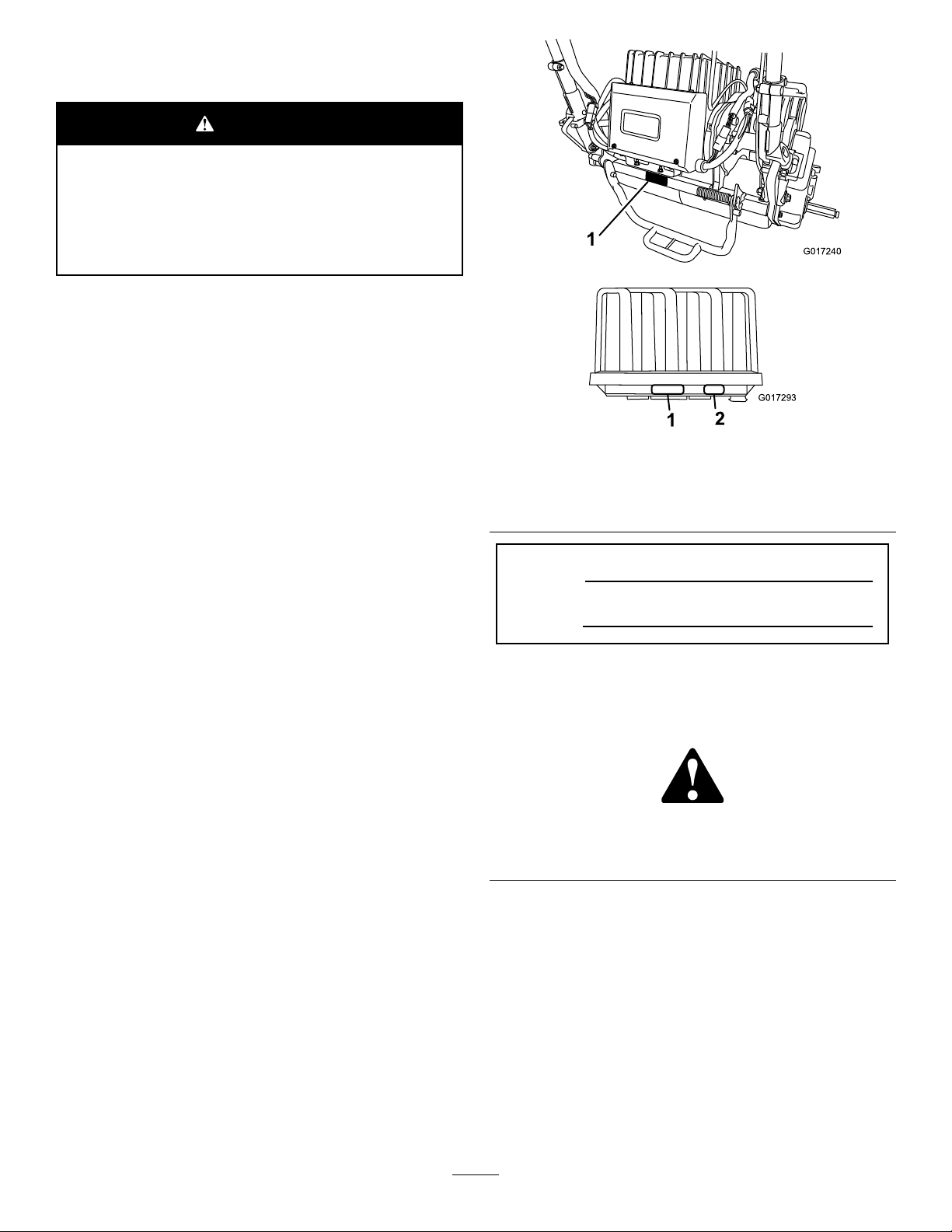
•Stopthemachineandshutoffthebatterybeforeservicing
oruncloggingthemachine.
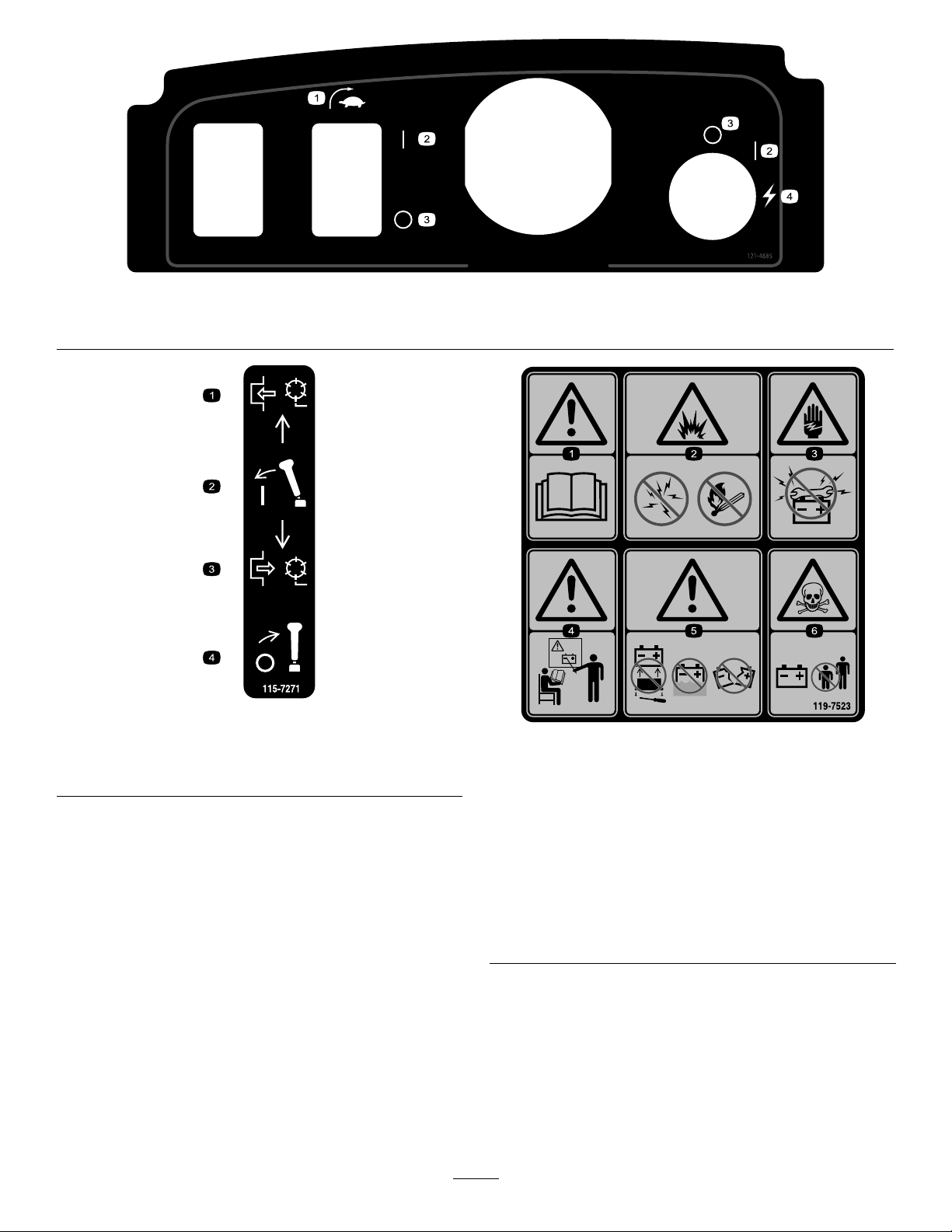
Improperlyusingormaintainingthismachinecanresult
ininjury.Toreducethepotentialforinjury,complywith
thesesafetyinstructionsandalwayspayattentiontothe
safety-alertsymbol,whichmeansCaution,Warning,or
Danger—personalsafetyinstruction.Failuretocomplywith
theseinstructionsmayresultinpersonalinjuryordeath.
Preparation
•Wearappropriateclothing,includingeyeprotection;
slip-resistant,substantialfootwear;andhearing
protection.Tiebacklonghair,securelooseclothing,and
donotwearjewelry.
•Inspecttheareawhereyouwillusethemachineand
removeallobjectsthatthemachinecouldthrow .
•Replacefaultysilencers.
•Evaluatetheterraintodeterminewhataccessoriesand
attachmentsareneededtoproperlyandsafelyperform
thejob.
•UseaccessoriesandattachmentsapprovedbytheThe
Toro®Companyonly.
•Checkthatoperator'spresencecontrols,safetyswitches,
andshieldsareattachedandfunctioningproperly.
Operation
•Operatethemachineonlyingoodvisibilityand
appropriateweatherconditions.Donotoperatethe
machinewhenthereistheriskoflightning.
•Beforeattemptingtostartthemachine,disengageall
bladeattachmentclutches,shiftintoneutral,andengage
theparkingbrake.
•Watchforholes,ruts,bumps,rocks,orotherhidden
objects.Uneventerraincouldcauseaslip-and-fall
accident.
•Watchoutfortrafcwhencrossingornearroadways.
•Stopthebladesrotatingbeforecrossingsurfacesother
thangrass.
•Donotchangetheenginegovernorsettingsoroverspeed
theengine.Operatingtheengineatexcessivespeedmay
increasethehazardofpersonalinjury.
•Shutoffthemachineanddisengagethedrivetothe
attachment:
–Beforeleavingtheoperator’sposition
–Beforeremovingthegrassbasket
–Beforemakingheightadjustmentunlessadjustment
canbemadefromtheoperator'sposition
–Beforeclearingblockages
–Beforechecking,cleaning,orworkingonthemower
–Afterstrikingaforeignobjectorifanabnormal
vibrationoccurs.Inspectthemowerfordamage
andmakerepairsbeforerestartingandoperatingthe
equipment.
Disengagedrivetoattachmentswhentransportingornot
inuse.
•Reducethethrottlesettingbeforeshuttingoffthe
machine.
•Slowdownandusecautionwhenmakingturnsand
crossingroadsandsidewalks.Stopthereelswhennot
mowing.
•Donotoperatethemowerifyouareill,tired,orunder
theinuenceofalcoholordrugs
•Useextremecarewhenapproachingblindcorners,
shrubs,trees,orotherobjectsthatmayblockyourview .
MaintenanceandStorage
•Keepallnuts,bolts,andscrewstighttobesurethe
equipmentisinsafeworkingcondition.
•Neverstorethemachinewherethereisanopename,
spark,orpilotlight,suchasonawaterheateroronother
appliances.
•Allowthemachinetocoolbeforestoringthemachine
inanyenclosure.
•Checkthegrasscatchercomponentsfrequentlyand
replacethemwiththemanufacturer’srecommendedparts
whennecessary.
4

•Keepallpartsingoodworkingconditionandallhardware
andhydraulicttingstightened.Replaceallwornor
damagedpartsanddecals.
•Becarefulduringadjustmentofthemachinetoprevent
entrapmentofthengersbetweenmovingbladesand
xedpartsofthemachine.
•Disengagedrives,disengagethecuttingunit,setthe
parkingbrake,andshutoffthemachine.Waitforall
movementtostopbeforeadjusting,cleaning,orrepairing.
•Cleangrassanddebrisfromthecuttingunit,drives,
mufers,coolingscreens,andthebatterytohelpprevent
res.
•Carefullyreleasepressurefromcomponentswithstored
energy.
•Disconnectthebatterybeforemakinganyrepairs.
Disconnectthenegativeterminalrstandthepositive
last.Reconnectthepositiverstandnegativelast.
•Usecarewhencheckingthereel.Wearglovesanduse
cautionwhenservicingthem.
Hauling
•Usecarewhenloadingorunloadingthemachine.
•Securethemachinefromrolling.
ToroMowerSafety
•Knowhowtoshutoffthemachinequickly.
•Alwaysstandbehindthehandlewhenstartingand
operatingthemachine.
•Whennearorcrossingroads,alwaysyieldtheright-of-way.
•Thegrassbasketmustbeinplace,duringthemowing
operation,formaximumsafety.Shutoffthemachine
beforeemptyingthebasket.
MaintenanceandStorage
•Donotopenoralterthebatterypackinanyway.Opening
itmayexposeyoutodangerouselectricalvoltage.The
warrantywillbevoidedifyouattempttoopenthebattery
pack.Withtheexceptionofthefuse,fusecover,and
labels,therearenoserviceablepartsonorinthebattery
pack.
•Ifthemachinemustberunningtoperformamaintenance
adjustment,keephands,feet,clothing,andanypartsof
thebodyawayfromthecuttingunit,attachmentsandany
movingparts.Keepeveryoneaway.
•Ifmajorrepairsareeverneededorifassistanceisdesired,
contactanAuthorizedToroDistributor.
•Toensureoptimumperformanceandcontinuedsafety
certicationofthemachine,useonlygenuineToro
replacementpartsandaccessories.Replacementparts
andaccessoriesmadebyothermanufacturerscouldbe
dangerous,andsuchusecouldvoidtheproductwarranty.
5

SafetyandInstructionalDecals
Safetydecalsandinstructionsareeasilyvisibletotheoperatorandarelocatednearanyareaofpotential
danger.Replaceanydecalthatisdamagedormissing.
decal120-9571
120-9571
1.Lowerthelevertodisengagethetraction.
decal120-9570
120-9570
1.Warning—stayawayfrommovingparts,keepallguards
andshieldsinplace.
decal120-9573
120-9573
1.ReadtheOperator'sManual.
2.Warning—donotoperatethemachineunlessyouare
trained.
3.Warning—keepbystandersawayfromthebattery.
4.Electricalshockhazard—donotallowtoolstoshortcircuit
batterypostswhenperformingmaintenance.
decal120-9593
120-9593
1.ReadtheOperator'sManual.4.Warning—stayawayfrommovingparts,keepallguardsand
shieldsinplace.
2.Warning—donotoperatethemachineunlessyouaretrained.5.Donottowthemachine.
3.Thrownobjecthazard—keepbystandersasafedistance
awayfromthemachine.
decal131-3111
131-3111
1.Fast2.Slow
decal120-9598
120-9598
1.Brake4.Parkingbrake
2.Releasehandleto
disengagethebrake.
5.Rotatethelatchtolockthe
parkingbrake;compress
thehandletoreleasethe
latch.
3.Compressthehandleto
engagethebrakelever.
6

decal121-4685
121–4685
1.EZ-Turnswitch2.On3.Off4.Start(machine)
decal115-7271
115-7271
1.Engagethereel.3.Disengagethereel.
2.Engagethelever.4.Disengagethelever.
decal119-7523
119-7523
1.Warning—readtheOperator'sManual.
2.Explosionhazard—nosparksoropenames.
3.Electricshockhazard—donotallowbatterypoststoshort
circuit.
4.Warning—donotoperatethismachineunlessyouare
trained.
5.Warning—donotremovebatterycover,donotplacein
water,donotuseabatterywithacrackedordamaged
housing.
6.Poisonhazard—keepchildrenawayfromthebattery.
7

decal119-7570
119-7570
1.Warning—readtheOperator'sManual;keepbatteries
sheltered,donotstoreindirectsunlight.
decal119-7571
119-7571
1.Warning—readtheOperator'sManual;donotuseabattery
withacrackedordamagedhousing.
8

Setup
LooseParts
Usethechartbelowtoverifythatallpartshavebeenshipped.
ProcedureDescriptionQty.Use
1Targetplate1Installthetargetplate.
Weightrod1
2Flange-headbolt1Installtheweightrod.
3Nopartsrequired–Preparethetractionunit(optional).
4Bolt(3/8x3/4inch)2Installthecuttingunittothetractionunit.
Handleretainer2
5Hairpincotter2Installthehandleretainers.
Batterypack1
Bolt(5/16x1/2inch)6
6Washer6
Installthebatterypack.
7Nopartsrequired–AdjusttheEZ-Turnsensor.
8Transportwheels(OptionalTransport
WheelKit,Model04123)2Installthetransportwheels.
9Grassbasket1Installthegrassbasket.
MediaandAdditionalParts
DescriptionQty.Use
Operator'sManual1
PartsCatalog1
OperatorTrainingMaterial1
CerticateofCompliance1
Readorviewthesematerialsbeforeoperatingthe
machine.
9

Note:Determinetheleftandrightsidesofthemachine
fromthenormaloperatingposition.
Note:Toinstalltheweightrodontoyourmachine,referto
theinstallationinstructionsinyourCuttingUnitOperator’s
Manual.
1
InstallingtheTargetPlate
Partsneededforthisprocedure:
1Targetplate
Procedure
1.Setupandpreparethecuttingunitasdescribedinthe
cuttingunitOperator’sManual.
2.Removethecenter,grass-shieldbolt(Figure3).
3.Installthetargetplatetothetopofthecuttingunit
usingtheboltthatyouremovedpreviously(Figure3).
1
2
G017294
g017294
Figure3
1.Center,grass-shieldbolt2.Targetplate
2
InstallingtheWeightRod
Partsneededforthisprocedure:
1Weightrod
1Flange-headbolt
Procedure
1.Enlargethelowerholeontherightsideofthecutting
unitusinga9mm(23/64inch)drillbit(Figure4).
G026123
g026123
Figure4
2.LubricatetheO-ringontheweightrod.
3.InserttheO-ringendoftheweightrodintothe
previouslydrilledhole.
4.Securethethreadedendoftheweightrodtotheframe
usingaange-headbolt(Figure5).
10

12
G026124
g026124
Figure5
1.Flange-headbolt2.Weightrod
3
PreparingtheTractionUnit
Forcuttingunit04251,02452,04253,or
04254
NoPartsRequired
Procedure
Ifyouareinstallingcuttingunit04251,02452,04253,or
04254onthistractionunit,completethefollowingsteps:
1.Positionthecuttingunitonaat,levelsurface.
2.Onbothpitcharms(Figure6),measure2.3mm(0.09
inch)inonthetabsandgrinddownthecorneras
showninFigure7.
g034505
Figure6
1.Pitcharms
g034506
Figure7
3.Painttherevealedmetaltopreventcorrosion.
4
InstallingtheCuttingUnitto
theTractionUnit
Partsneededforthisprocedure:
2Bolt(3/8x3/4inch)
Procedure
Note:Toinstalltheweightrodontoyourmachine,referto
theinstallationinstructionsinyourCuttingUnitOperator’s
Manual.
1.Placethemoweronitsdrumsonalevelsurface.
2.Lowerthekickstandandpushinthelockingpinto
lockthekickstandintheserviceposition(Figure8).
Note:Allowthemachinetorestonthelocked
kickstand.
Note:Placethekickstandinthispositionwhenever
youremovethereel.Thiswillkeepthemachinefrom
tippingbackwardontothehandle.
11

G017356
1
2
3
g017356
Figure8
1.Kickstand—storage
position
3.Kickstand—service
position
2.Lockingpin
3.Pushthecuttingunitunderthetractionunitandtothe
lefttoengagethetransmissioncoupling(Figure9).
g000483
Figure9
1.Transmissioncoupling
4.Maneuverthetractionunitframe(Figure10)forward
untilitengagesthecuttingunitpivotarms.
G017242
1
2
3
g017242
Figure10
Batteryplatformnotshown
1.Telescopingcoupler3.Bolt
2.Cuttingunithexshaft
5.Securethetractionunitframetothecuttingunitpivot
armswith2bolts(3/8x3/4inch)(Figure10).
Note:Toremovethecuttingunit,justloosenthe2
bolts(3/8x3/4inch)approximately1-1/2turnsand
rotatethepivotarmsout.
6.Pushdownonthekickstandtoreleasethespring
loadedlockingpinandallowthekickstandtorotate
uptothestorageposition.
7.Settheheight-of-cutofthereelasdescribedinthereel
Operator’sManual.
5
InstallingtheHandleRetainers
Partsneededforthisprocedure:
2Handleretainer
2Hairpincotter
Procedure
1.Whilesupportingthehandle,removethecableties
securingthehandleclampstothesideplates(Figure
11).
12

g017355
1
2
g017355
Figure11
1.Hairpincotter2.Handleretainer
2.Pivotthehandletothedesiredoperatingposition,
insertahandleretaineroverthehandleclampandinto
thematchingholesinthesideplate(Figure11).
3.Securetheclampinpositionwithahairpincotter
(Figure11).
4.Repeattheprocedureontheoppositesideofthe
handle.
5.Adjustthehandleheighttothedesiredposition;refer
toAdjustingtheHandleHeight(page22).
Note:Themachineisshippedwiththehandle
adjustedtothelowestposition.Themachineis
traditionallyoperatedwiththehandletelescopedoutto
itsmaximumheight.
6
InstallingtheBatteryPack
Partsneededforthisprocedure:
1Batterypack
6Bolt(5/16x1/2inch)
6Washer
Procedure
1.Removethebatterypackfromitscarton,savingthe
cartonandallpackingmaterialforfutureuse.
Important:Savethecartonandallpacking
materials.Ifyoueverneedtoshipthebatteryfor
maintenance,warranty,orrecycling,youwillneed
thisspecialpackaging.
RefertotheInstallationInstructionsincluded
withtheBatteryShippingKit(aPDFleof
theseinstructionsisavailableatnochargefrom
www.Toro.com).
2.Cutthecabletiesecuringthebatterychargertothe
batterybaseonthemachineandremovethecharger.
3.Disconnectthesmallconnectoronthepacktothe
machinewireharnessfromthemainwireharness
(Figure16).
4.Removethetallnutthatsecurestherearofthebattery
basetothemachineframe(Figure12).
G017238
1
g017238
Figure12
1.Tallnut
5.Loosenthe2pivotbolts/nutsahalfturneach(Figure
13).
12
3
4
5
G017295
g017295
Figure13
1.Batterypack4.Pivotbolts
2.Batteryplatform5.Lockingholes
3.Boltandwasher
6.Raisethebatteryplatformuntilthelockingholesinthe
baseandframealign(Figure13).
Note:Slideascrewdriverorothersteelrodthrough
theholestoholdtheplatformintheraisedposition.
13

7.Placethebatterypackonthebasewiththeconnector
porttowardtherearofthemachine.
8.Securethebatterypacktothebaseusing6bolts(5/16
x1/2inch)andwashers.
Note:Torqueeachboltto11.3to14N∙m(100to130
in-lb).
9.Lineupthetabsontheinsideoftheharnesspower
plugwiththeslotsinthebatterypackreceptacle.
Note:Presstheharnessconnectorintothebattery
connector(Figure14andFigure15).
G017236
1
2
3
4
g017236
Figure14
1.Battery-packreceptacle3.Packthemachinetothe
wire-harnessplug
2.Lockingcollar4.Boltsecuringthebattery
pack
G017358
g017358
Figure15
10.Rotatethelockingcollarontheharnessplugclockwise
untilitengageswiththebatteryreceptacleandbegins
topullintowardthebattery.
Note:Continueturningitanother120degrees(1/3
ofaturn)untilitfullyseats.
Note:Ifyoucannotmatethebatterypackreceptacle
withthemachinewireharnessplugwhilethebattery
packisinstalled,youcaninsteadconnecttheharness
tothebatterypackandtheninstallthebatterypack.
Removethemainpowersupplyconnector(Figure
17)fromthebatterybase.Installtheconnectorto
thebatteryasdescribed.Installthebatterytothe
base,threadingtheattachedwireharnessthroughthe
appropriatehole,andthensecurethemainpower
supplyconnectortothebatterybaseusingthefasteners
previouslyremoved.
11.Removethescrewdriverholdingthebatterybaseinthe
upposition,andgentlylowerthebatteryplatformto
themachineframe.
Important:Donotpinchthewireharness
betweentheframeandplatform.
12.Securethebatteryplatformtothemachineframewith
thetallnutremovedinstep4.
13.Tightenthepivotfastenersloosenedinstep5.
14.Routethepacktomachinewireharnessunderand
behindthemainharnessontheleftsideofthemachine
andconnectthesmall,6-pinconnectorontheharness
tothematchingconnectoronthemainwireharnessas
showninFigure16.
G017235
1
2
g017235
Figure16
1.Connectoronthemain
wireharness
2.Smallconnectorfromthe
packtomachinewire
harness
14

15.Turnonandturnoffthemachinetoensurethatthe
batterychargescompletely.
16.ConnecttheT-handleconnectorfromthemainwire
harnesstothemainpowersupplyconnectoronthe
batterybase(Figure17).
G017237
12
g017237
Figure17
1.T-handleconnector2.Mainpowersupply
connectoronthebattery
platform
17.Chargethebatteryasdescribedintheinstructionsthat
camewiththebatterycharger.
Note:Thebatteryisshippedwithapartialcharge
(approximately40%).Thisisenoughchargeforyouto
performfunctionalchecksonthemachineandmove
itasneededtocompletesetup,butyoushouldfully
chargethebatterybeforeusingthemachine.
7
AdjustingtheEZ-TurnSensor
NoPartsRequired
Procedure
1.Ensurethattheunitisonaat,levelsurfacewiththe
tractiondrumontheground.
2.Loosenthejamnutsonthesensorandadjustthe
sensorsothat1threadisvisiblepastthelowerjamnut
(Figure18).
1
2
3
45
6
7
G0172357
8
g017357
Figure18
1.Sensorlight(ontop)5.3.8cm(1-1/2inches)block
2.Jamnuts6.Targetplate
3.EZ-Turnsensor7.Bracketfasteners
4.Roller8.Sensorbracket
3.Tightenthejamnutstosecurethesensor.
4.Placea3.8cm(1-1/2inches)blockunderthefront
cuttingunitroller(Figure18).
5.Loosenthefastenerssecuringthesensorbracketto
theframe(Figure18).
6.Turnonthemachine;refertoTurningontheMachine
(page23).
7.SettheEZ-TurnswitchtotheONposition;referto
EZ-TurnSwitch(page18).
8.Rotatethesensorbrackettowardthetargetplateuntil
thelightontopofthesensorilluminates(Figure18).If
itwasalreadyilluminated,rotateitawayfromthetarget
plateuntilitgoesoutandthenreversedirectionjust
untilitilluminatesagain.
9.Tightenthebracketfasteners.
10.Removetheblockfromundertherollerandplacethe
machineonthekickstand.
11.Ensurethatthetargetplatedoesnotcontactthegrass
shield.
Note:Ifitdoes,loosenthebracketfastenersand
rotatetheswitchupjustuntilthetargetplateisno
longertouchingthegrassshield.
12.Turnoffthemachine.
15

8
InstallingtheOptional
TransportWheels
Partsneededforthisprocedure:
2Transportwheels(OptionalTransportWheelKit,
Model04123)
Procedure
1.Pushthekickstanddownwithyourfootandpullup
onthehandlesupportuntilthekickstandhasrotated
forward,overcenter(Figure19).
G017244
1
g017244
Figure19
1.Kickstand
2.Pressthewheellockingcliptowardthecenterofthe
wheelandslidethewheelontothehexshaft(Figure
20).
g000475
Figure20
1.Lockingclip
3.Rotatethewheelbackandforthuntilitslides
completelyontotheaxleandthelockingclipissecured
inthegrooveontheaxleshaft.
4.Repeattheprocedureontheoppositesideofthe
machine.
5.Inatethetiresto83-103kPa(12-15psi).
6.Carefullylowerthemachineoffthekickstand.
9
InstallingtheGrassBasket
Partsneededforthisprocedure:
1Grassbasket
Procedure
1.Graspthebasketbythehandle(Figure21).
16

G017245
1
g017245
Figure21
1.Baskethooks
2.Guidethebasketlipbetweenthecuttingunitside
platesandoverthefrontroller(Figure21).
3.Installthebaskethooksovertheframeloop(Figure
21).
Important:Ifyoueverdropthebasket,examinethe
pitcharmcontactpointsnearthelowerlipofthebasket
fordamage(Figure22).Straightenthembeforeusing
thebasket.Usingthebasketwithbentpitcharmcontact
pointscoulddamagethereel.
1
g024292
g024292
Figure22
1.Pitcharmcontactpoints
ProductOverview
G017155
123
4
5
6
7
8
9
g017155
Figure23
1.Operator-presencecontrol6.Grassbasket
2.Tractionandreeldrive
engagementlever
7.Cuttingunit
3.Handle8.Transportwheels
4.Servicebrake9.Electricmotor
5.Batterypack
17

Controls
G017156
1
2
3
4
5
6
789
g017156
Figure24
1.EZ-Turnswitch6.Handle
2.Openspaceforoptional
lights
7.InfoCenterLCDdisplay
3.Parking-brakelatch8.Keyswitch
4.Servicebrake9.Speedcontrol
5.Operator-presencecontrol
EZ-TurnSwitch
TheEZ-turnswitch(Figure24)enablesordisablesthe
EZ-Turnfeature.EZ-Turnisafeaturethatautomatically
slowsthemachinewheneveryouraisethecuttingunitoffthe
groundduringmowing.Thisallowsyoutomaketheturnsat
theendofeachmowingpassataslowerspeed.Youcanuse
theswitchatanytime,evenwhilemowing.
Thisfeatureonlyreducesthegroundspeedwhenthereelis
engagedandliftedofftheground.Ithasnoeffectonground
speedwhenthereelisdisengaged.Ifthisfeatureisactivated
whilemowingandyouturnoffthereel,themachinewill
speedup.Ifyouaremowingataslowspeedalready,the
EZ-Turnfeaturewillnotslowthemachineonaturn.
ServiceBrake
Theservicebrake(Figure25)islocatedontheleftfrontside
ofthehandle.Pullingtheleverbackappliestheservicebrake.
Ifyouoperatethemachinewiththebrakeon,itmoves,but
withhighresistanceandincreasedpowerconsumption.
g016853
Figure25
1.Parking-brakelatch2.Servicebrake
Parking-BrakeLatch
Usetheparking-brakelatch(Figure25)withtheservice
brake.Rotatetheparking-brakelatchtowardthebrakehandle
toholdtheservicebrakeinplace.Pullthebrakeleverto
release.Thetraction-controlleverdoesnotengagewiththe
latchengaged.
Operator-PresenceControl(OPC)
Youmustengagetheoperator-presencecontrol(Figure24)
beforeengagingthetractionlever.IfyoureleasetheOPC
duringoperation,thetractionleverreturnstoneutralbutthe
machinedoesnotturnoff.
InfoCenterLCDDisplay
TheInfoCenterLCDdisplayshowsinformationaboutyour
machineandbatterypack,suchasthecurrentbatterycharge,
thespeed,diagnosticsinformation,andmore(Figure24).
Formoreinformation,refertoUsingtheInfoCenterLCD
Display(page27).
KeySwitch
Thekeyswitch(Figure24)has3positions:OFF,RUN,and
START.Withthebrakeoffandthetractiondrivedisengaged,
movetheswitchtotheSTARTpositionuntiltheInfoCenter
displaylightsup,thenreleaseittotheRUNposition.Turnitto
theOFFpositionandremovethekeytoturnoffthemachine.
18

TractionandReelDriveEngagement
Lever
Thetractionandreeldriveengagementlever(Figure26)is
locatedonthefrontrightsideofthecontrolpanel.For
transportoperation,theleverhas2positions:Neutraland
Forward.Pushingtheleverforwardengagesthetraction
drive.
Note:Tomovethelever,youmustrstengagethe
operator-presencecontrol.
g000494
Figure26
1.Neutral3.Tractiondrive-engaged
(transport)
2.Tractiondriveinneutral
andreeldriveoff
4.Tractiondriveandreel
driveengaged
Forreeloperation,theleverhas2positions:Engageand
Disengage.Movethetopofthelevertotheleft,thenforward
toengagethereelandbeginmowing.Pushthelevertothe
righttodisengagethereelandcontinueforwardmotionor
pullbackonittodisengageboththereelandthetraction
drive.
Note:Ifyoureleasetheoperator-presencecontrol,thelever
returnstoNeutralandthemachinestops.
AutomaticMotorBrake
Themachineisequippedwithanautomaticmotorbrakethat
preventsitfromrollingwhenthemachineisstopped.The
motorbrakeisonwheneverthetractiondriveisinneutral
oryoumovethespeedcontroltothezero-speedposition,
exceptinthefollowingcircumstances:
•Whenthemachineisturnedoff,usetheparkingbrake
latchtosecurethemachine.
•Whenyoustartthemachinewiththekeyswitch,the
motorbrakeisinitiallydisengaged.Afterdrivingthe
machine,themotorbrakefunctionsnormally.
•Ifyoumovethespeedcontroltozerospeedwhilethe
reelsareengaged(i.e.,whilemowing),thebrakedoes
notengage.Thisfeatureallowsyoutomovetothezero
positionwhilemowingandpullthemachinerearward
tomakecoursecorrections.
Kickstand
Thekickstand(Figure28)ismountedontotherearofthe
machine;toraisetherearofthemachineforinstallingor
removingthetransportwheelsandtokeepthemachinefrom
fallingontothehandlewhenyouremovethereel.
•Tousethekickstandtoinstallthetransportwheels,
lowerthekickstandtothegroundandstepdownonthe
kickstandloopwhilepullingupandbackonthelower
centermachinehandle(Figure27).
Important:Putonlyfootpressuredownonthe
kickstandloop,anduseonlythelowercenter
machinehandletoraisethemachine.Attemptingto
raisethemachineontothekickstandbyanyother
meanscancauseinjury.
g018793
g018793
Figure27
1.Lowercentermachine
handle
2.Kickstandloop
19
This manual suits for next models
3
Table of contents
Other Toro Lawn Mower manuals

Toro
Toro TimeCutter User manual

Toro
Toro 71242 User manual

Toro
Toro TimeCutter 74601 User manual

Toro
Toro 74179 User manual

Toro
Toro Z Master 8000 74312 User manual

Toro
Toro Greensmaster TriFlex 3400 User manual

Toro
Toro 74410 User manual

Toro
Toro 18-44Z User manual

Toro
Toro Reelmaster 3555 Series User manual

Toro
Toro 03681 User manual

Toro
Toro 20812 User manual

Toro
Toro Greensmaster 3120 User manual

Toro
Toro Reelmaster 5610-D User manual

Toro
Toro 03698 User manual

Toro
Toro 39494 User manual

Toro
Toro Wheel Horse 14-38 HXL User manual

Toro
Toro Groundsmaster 360 User manual

Toro
Toro 30314TE User manual

Toro
Toro Recyler 20333 User manual

Toro
Toro GrandStand 74568TE User manual