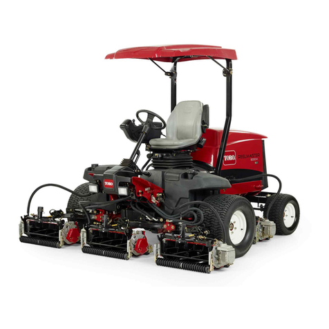
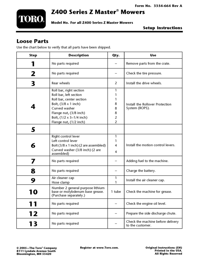
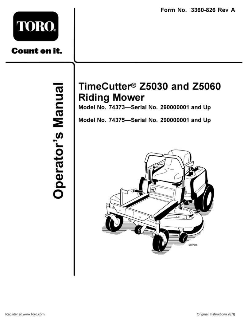
Toro 3806 User manual

FormNo.3358-628RevA
Reelmaster®6500-Dand6700-D
TractionUnit
ModelNo.03806—SerialNo.270000001andUp
ModelNo.03807—SerialNo.270000001andUp
ModelNo.03808—SerialNo.270000001andUp
Registeratwww.Toro.com.OriginalInstructions(EN)

Warning
CALIFORNIA
Proposition65Warning
Dieselengineexhaustandsomeofits
constituentsareknowntotheStateof
Californiatocausecancer,birthdefects,
andotherreproductiveharm.
Important:Thisengineisnotequippedwitha
sparkarrestermufer.ItisaviolationofCalifornia
PublicResourceCodeSection4442touseoroperate
theengineonanyforest-covered,brush-covered,or
grass-coveredland.Otherstatesorfederalareas
mayhavesimilarlaws.
Introduction
Readthisinformationcarefullytolearnhowtooperate
andmaintainyourproductproperlyandtoavoidinjury
andproductdamage.Youareresponsibleforoperating
theproductproperlyandsafely.
YoumaycontactTorodirectlyatwww.Toro.comfor
productandaccessoryinformation,helpndinga
dealer,ortoregisteryourproduct.
Wheneveryouneedservice,genuineToroparts,
oradditionalinformation,contactanAuthorized
ServiceDealerorToroCustomerServiceandhave
themodelandserialnumbersofyourproductready.
Figure1identiesthelocationofthemodelandserial
numbersontheproduct.Writethenumbersinthe
spaceprovided.
Figure1
1.Locationofthemodelandserialnumbers
ModelNo.
SerialNo.
Thismanualidentiespotentialhazardsandhas
safetymessagesidentiedbythesafetyalertsymbol
(Figure2),whichsignalsahazardthatmaycauseserious
injuryordeathifyoudonotfollowtherecommended
precautions.
Figure2
1.Safetyalertsymbol.
Thismanualusestwootherwordstohighlight
information.Importantcallsattentiontospecial
mechanicalinformationandNoteemphasizesgeneral
informationworthyofspecialattention.
©2007—TheToro®Company
8111LyndaleAvenueSouth
Bloomington,MN554202
Contactusatwww.Toro.com.
PrintedintheUSA.
AllRightsReserved

Contents
Introduction.................................................................2
Safety...........................................................................4
SafeOperatingPractices.......................................4
ToroMowerSafety...............................................5
SoundPressureLevel...........................................6
VibrationLevel.....................................................6
SafetyandInstructionalDecals.............................7
Setup..........................................................................12
1CheckingFluidLevels......................................12
2InstallingCuttingUnitsModels03860,03861
and03862.......................................................12
3InstallingCuttingUnitsModels03863and
03864.............................................................14
4MakingAlternateCuttingUnit
Adjustments...................................................18
5AddingRearBallast..........................................19
6InstallingCEDecals........................................19
7ReadingtheManualsandStoringAdditional
Parts...............................................................19
ProductOverview......................................................20
Controls.............................................................20
Specications.....................................................24
Attachments/Accessories...................................24
Operation...................................................................24
CheckingtheEngineOil.....................................24
CheckingtheCoolingSystem..............................25
FillingtheFuelTank...........................................26
CheckingtheHydraulicFluid..............................26
CheckingtheTirePressure.................................27
CheckingtheReeltoBedknifeContact................27
StartingandStopping.........................................27
BleedingtheFuelSystem....................................27
PushingorTowingtheMachine..........................28
CheckingtheInterlockSwitches.........................29
FaultMemoryandRetrieval................................30
HydraulicSolenoidValveFunctions....................31
OperatingTips...................................................31
Maintenance...............................................................33
RecommendedMaintenanceSchedule(s)................33
ServiceIntervalChart.........................................34
DailyMaintenanceChecklist...............................34
Lubrication.............................................................35
GreasingtheBearingsandBushings....................35
EngineMaintenance...............................................37
ServicingtheAirCleaner....................................37
ServicingtheEngineOilandFilter......................38
AdjustingThrottle..............................................38
FuelSystemMaintenance.......................................39
FuelTank...........................................................39
FuelLinesandConnections................................39
FuelFilter/WaterSeparator................................39
ReplacingtheFuelPre-Filter...............................39
BleedingAirFromInjectors...............................40
ElectricalSystemMaintenance................................41
BatteryCare.......................................................41
Fuses..................................................................41
OptionalLighting...............................................42
DriveSystemMaintenance.....................................43
CheckingtheTorqueoftheWheelNutsor
Bolts..............................................................43
CheckingthePlanetaryGearDrive
Oil..................................................................43
ChangingthePlanetaryGearDrive
Oil..................................................................43
CheckingtheRearAxleLubricant.......................44
ChangingtheRearAxleLubricant.......................44
RearWheelToe-In.............................................45
AdjustingtheTractionDriveforNeutral.............45
CoolingSystemMaintenance..................................46
RemovingDebris...............................................46
MaintainingtheCoolingSystem..........................46
BrakeMaintenance.................................................47
AdjustingtheServiceBrakes...............................47
BeltMaintenance....................................................47
CheckingtheAlternatorBelt...............................47
HydraulicSystemMaintenance...............................48
ChangingtheHydraulicFluid.............................48
ReplacingtheHydraulicFilter.............................48
CheckingtheHydraulicLinesandHoses.............48
HydraulicSystemTestPorts...............................49
CuttingUnitMaintenance.......................................50
CuttingUnitKickstandModels03863and
03864.............................................................50
Backlapping........................................................50
AdjustingtheCuttingUnitLoweringRate
......................................................................52
LiftedHeightofOuterFrontCuttingUnits
(EnablePosition)............................................53
AdjustingtheTraveloftheFrontThree
CuttingUnits..................................................53
Storage.......................................................................55
TractionUnit......................................................55
Engine...............................................................55
Schematics.................................................................56
3
Safety
ThismachinemeetsorexceedsCENstandard
EN836:1997,ISOstandard5395:1990,andANSI
B71.4-1999specicationsineffectatthetimeof
productionwhen,ballastisadded;refertoAdding
RearBallastinSetup,page12.
Note:Theadditionofattachmentsmadeby
othermanufacturersthatdonotmeetAmerican
NationalStandardsInstitutecerticationwillcause
noncomplianceofthismachine.
Improperuseormaintenancebytheoperatororowner
canresultininjury.Toreducethepotentialforinjury,
complywiththesesafetyinstructionsandalwayspay
attentiontothesafetyalertsymbol,whichmeans
CAUTION,WARNING,orDANGER-“personalsafety
instruction.”Failuretocomplywiththeinstructionmay
resultinpersonalinjuryordeath.
SafeOperatingPractices
ThefollowinginstructionsarefromtheCENstandard
EN836:1997,ISOstandard5395:1990,andANSI
B71.4-1999.
Training
•ReadtheOperator’sManualandothertraining
material.Iftheoperator(s)ormechanic(s)cannot
readEnglishitistheowner’sresponsibilitytoexplain
thismaterialtothem.
•Becomefamiliarwiththesafeoperationofthe
equipment,operatorcontrols,andsafetysigns.
•Alloperatorsandmechanicsshouldbetrained.The
ownerisresponsiblefortrainingtheusers.
•Neverletchildrenoruntrainedpeopleoperateor
servicetheequipment.Localregulationsmayrestrict
theageoftheoperator.
•Theowner/usercanpreventandisresponsiblefor
accidentsorinjuriesoccurringtohimselforherself,
otherpeopleorproperty.
Preparation
•Evaluatetheterraintodeterminewhataccessories
andattachmentsareneededtoproperlyand
safelyperformthejob.Onlyuseaccessoriesand
attachmentsapprovedbythemanufacturer.
•Wearappropriateclothingincludinghardhat,safety
glassesandearprotection.Longhair,looseclothing
orjewelrymaygettangledinmovingparts.
•Inspecttheareawheretheequipmentistobeused
andremoveallobjectssuchasrocks,toysandwire
whichcanbethrownbythemachine.
•Useextracarewhenhandlingdieselfuel.Itis
ammableandvaporsareexplosive.
Useonlyanapprovedcontainer.
•Neverremovegascaporaddfuelwithengine
running.Allowenginetocoolbeforerefueling.Do
notsmoke.
•Neverrefuelordrainthemachineindoors.
•Checkthatoperator’spresencecontrols,safety
switchesandshieldsareattachedandfunctioning
properly.Donotoperateunlesstheyarefunctioning
properly.
Operation
•Neverrunanengineinanenclosedarea.
•Onlyoperateingoodlight,keepingawayfromholes
andhiddenhazards.
•Besurealldrivesareinneutralandparkingbrakeis
engagedbeforestartingengine.Onlystartengine
fromtheoperator’sposition.Useseatbeltsif
provided.
•Slowdownanduseextracareonhillsides.Besure
totravelintherecommendeddirectiononhillsides.
Turfconditionscanaffectthemachine’sstability.
Usecautionwhileoperatingneardrop-offs.
•Slowdownandusecautionwhenmakingturnsand
whenchangingdirectionsonslopes.
•Neveroperatewithguardsnotsecurelyinplace.Be
sureallinterlocksareattached,adjustedproperly,
andfunctioningproperty.
•Donotchangetheenginegovernorsettingor
overspeedtheengine.
•Stoponlevelground,raisethecuttingunits,
disengagedrives,engageparkingbrake(ifprovided),
shutoffenginebeforeleavingtheoperator’sposition
foranyreasonincludingemptyingthegrassbaskets.
•Stopequipmentandinspectthemachineafter
strikingobjectsorifanabnormalvibrationoccurs.
Makenecessaryrepairsbeforeresumingoperations.
•Keephandsandfeetawayfromthecuttingunits.
•Lookbehindanddownbeforebackinguptobesure
ofaclearpath.
•Nevercarrypassengersandkeeppetsandbystanders
away.
4

•Slowdownandusecautionwhenmakingturns
andcrossingroadsandsidewalks.Stopreelsifnot
mowing.
•Donotoperatethemowerundertheinuenceof
alcoholordrugs.
•Usecarewhenloadingorunloadingthemachine
intoatrailerortruck.
•Usecarewhenapproachingblindcorners,shrubs,
trees,orotherobjectsthatmayobscurevision.
MaintenanceandStorage
•Disengagedrives,raisethecuttingunits,setparking
brake,stopengineandremovekey.Waitforall
movementtostopbeforeadjusting,cleaningor
repairing.
•Cleangrassanddebrisfromcuttingunits,drives,
mufers,andenginetohelppreventres.Cleanup
oilorfuelspillage.
•Letenginecoolbeforestoringanddonotstorenear
ame.
•Shutofffuelwhilestoringortransporting.Donot
storefuelnearamesordrainindoors.
•Parkmachineonlevelground.Neverallowuntrained
personneltoservicemachine.
•Usejackstandstosupportcomponentswhen
required.
•Carefullyreleasepressurefromcomponentswith
storedenergy.
•Disconnectbatteryandremovesparkplugwire
beforemakinganyrepairs.Disconnectthenegative
terminalrstandthepositivelast.Reconnect
positiverstandnegativelast.
•Usecarewhencheckingthereels.Wearglovesand
usecautionwhenservicingthem.
•Keephandsandfeetawayfrommovingparts.If
possible,donotmakeadjustmentswiththeengine
running.
•Chargebatteriesinanopenwellventilatedarea,
awayfromsparkandames.Unplugchargerbefore
connectingordisconnectingfrombattery.Wear
protectiveclothinganduseinsulatedtools.
•Keepallpartsingoodworkingconditionandall
hardwareandhydraulicttingstightened.Replaceall
wornordamageddecals.
ToroMowerSafety
Thefollowinglistcontainssafetyinformationspecicto
Toroproductsorothersafetyinformationthatyoumust
knowthatisnotincludedintheANSIstandards.
Thisproductiscapableofamputatinghandsand
feetandthrowingobjects.Alwaysfollowallsafety
instructionstoavoidseriousinjuryordeath.
Useofthisproductforpurposesotherthanitsintended
usecouldprovedangeroustouserandbystanders.
Operation
•Sitontheseatwhenstartingandoperatingthe
machine.
•Alwayswearsubstantialshoes.Donotoperatethe
machinewhilewearingsandals,tennisshoes,or
sneakers.
•Wearingsafetyshoesandlongpantsisadvisableand
requiredbysomelocalordinancesandinsurance
regulations.
•Handlefuelcarefully.Wipeupanyspills.
•Checkthesafetyinterlockswitchesdailyforproper
operation.Ifaswitchshouldfail,replacetheswitch
beforeoperatingthemachine.Aftereverytwoyears,
replaceallthreeinterlockswitchesinthesafety
system,regardlessiftheyareworkingproperlyor
not.
•Usingthemachinedemandsattention.Toprevent
lossofcontrol:
Donotdriveclosetosandtraps,ditches,creeks,or
otherhazards.
•Reducespeedwhenmakingsharpturns.Avoid
suddenstopsandstarts.
•Donottouchtheengine,mufer,orexhaustpipe
whiletheengineisrunningorsoonafterithas
stoppedbecausetheseareascouldbehotenough
tocauseburns.
•Ifacuttingunitstrikesasolidobjectorvibrates
abnormally,stopimmediately,turntheengineoff,
waitforallmotiontostop,andinspectthemachine
fordamage.Adamagedreelorbedknifemustbe
repairedorreplacedbeforeoperationiscontinued.
•Traverseslopescarefully.Donotstartorstop
suddenlywhentravelinguphillordownhill.
•Theoperatormustbeskilledandtrainedinhowto
driveonhillsides.Failuretousecautiononslopesor
hillsmaycauselossofcontrolandcausethevehicle
totiporroll,possiblyresultinginpersonalinjury
ordeath.On4wheeldrivemodels,alwaysusethe
seatbeltandRollOverProtectionSystem(ROPS)
together.
•Iftheenginestallsorlosesheadwayandcannotmake
ittothetopofaslope,donotturnthemachine
around.Alwaysbackslowly,straightdowntheslope.
5

•Whenapersonorpetappearsunexpectedlyin
ornearthemowingarea,stopmowing.Careless
operation,combinedwithterrainangles,ricochets,
orimproperlypositionedguardscanleadtothrown
objectinjuries.Donotresumemowinguntilthe
areaiscleared.
•Donotparkonslopesunlessthewheelsarechocked
orblocked.
MaintenanceandStorage
•Makesureallhydrauliclineconnectorsaretightand
allhydraulichosesandlinesareingoodcondition
beforeapplyingpressuretothesystem.
•Keepyourbodyandhandsawayfrompinhole
leaksornozzlesthatejecthydraulicuidunderhigh
pressure.Usepaperorcardboard,notyourhands,
tosearchforleaks.Hydraulicuidescapingunder
pressurecanhavesufcientforcetopenetratethe
skinandcauseseriousinjury.
•Beforedisconnectingorperforminganyworkon
thehydraulicsystem,allpressureinthesystemmust
berelievedbystoppingtheengineandloweringthe
cuttingunitsandattachmentstotheground.
•Iftheenginemustberunningtoperforma
maintenanceadjustment,keephands,feet,clothing,
andanypartsofthebodyawayfromthecutting
units,attachmentsandanymovingparts.Keep
everyoneaway.
•Theenginemustbeshutoffbeforecheckingtheoil
oraddingoiltothecrankcase.
•Ifmajorrepairsareeverneededorifassistanceis
desired,contactanAuthorizedToroDistributor.
•Tomakesureofoptimumperformanceand
continuedsafetycerticationofthemachine,use
onlygenuineTororeplacementpartsandaccessories.
Replacementpartsandaccessoriesmadebyother
manufacturerscouldbedangerous,andsuchuse
couldvoidtheproductwarranty.
SoundPressureLevel
ThisunithasanequivalentcontinuousA-weighted
soundpressurelevelattheoperatorearof89dBA,
basedonmeasurementsofidenticalmachinesperEN
11094andEN836.
VibrationLevel
Thisunitdoesnotexceedavibrationlevelof2.5m/s²at
thehandsbasedonmeasurementsofidenticalmachines
perEN1033procedures.
Thisunitdoesnotexceedavibrationlevelof.5m/s²
attheposteriorbasedonmeasurementsofidentical
machinesperEN1032procedures.
6

SafetyandInstructionalDecals
Safetydecalsandinstructionsareeasilyvisibletotheoperatorandarelocatednearanyareaof
potentialdanger.Replaceanydecalthatisdamagedorlost.
104-5229
1.ReadtheOperator’s
Manual.
3.Fuseforheadlights
(optional)
2.Fuseforstarter
105-7506
1.ReadtheOperator’s
Manual.
4.Engine—preheat
2.Engine—stop5.Engine—start
3.On
93-6693
1.Crushinghazardofhand—waitformovingpartstostop.
93-6680
93-6686
1.Hydraulicoil
2.ReadtheOperator’sManual.
93-6699
1.Machinespeed3.Continuousvariable
setting
2.Slow4.Fast
2
1
93-9425
1.ReadtheOperator’sManual.
2.Hydraulichosesareunderpressure—stayawayfrom
movingparts.
93-6696
1.Storedenergyhazard—readtheOperator’sManual.
7

93-6687
1.Donotstephere.
93-6689
1.Warning—donotcarrypassengers.
93-6681
1.Cutting/dismemberment—hazard,fan-stayawayfrom
movingparts..
93-1265
1.Hotsurface/burnhazard—stayasafedistancefromthe
hotsurface.
104-9298
1.ReadtheOperator’sManual.
93-1263
93-1263
1.ReadtheOperator’sManual.
2.Toengagetheparkingbrake,connectthebrakepedalswith
thelockingpin,pushdownonbothpedals,andpullthe
brakelatchout.
3.Toreleasetheparkingbrake,pressbothpedalsuntilthe
parkingbrakelatchretracts.
4.Danger—reelsenabled.
108-6708
8

106-6754
1.Warning—donottouchthehotsurface.
2.Cutting/dismembermenthazard,fanandentanglement
hazard,belt—stayawayfrommovingparts.
67-7960
105-0123
Model03807
1.Throttle—slow7.Reelsdisabled—liftandlower
2.Throttle—fast8.Headlights(optional)
3.Reelsraisedandoff9.Headlights—On
4.Reelsloweredandonwhenenabled—forwardandbacklap10.Headlights—Off
5.Reels—enabled11.ReadtheOperatorsManual.
6.Reelsdisabled—liftonly
104-9296
Models03806and03807
1.Throttle—slow4.Reelsloweredandonwhen
enabled—forwardand
backlap
7.Reelsdisabled—liftand
lower
10.Headlights—Off
2.Throttle—fast5.Reelsenabled8.Headlights(optional)11.ReadtheOperator’s
Manualforfurther
instructions.
3.Reelsraisedandoff6.Reelsdisabled—liftonly9.Headlights—On
9

104-9294
1.ReadtheOperator’s
Manual.
3.Warning—Readthe
Operator’sManual.
5.Warning—keepbystanders
asafedistancefromthe
machine.
7.Warning—usearollover
protectionsystemandwear
theseatbelt.
2.Donottowthemachine.4.Cuttinghazardofhand
orfoot—stayawayfrom
movingparts.
6.Warning—locktheparking
brake,stoptheengine,and
removetheignitionkey
beforeleavingthemachine.
8.Tippinghazard—lowerthe
cuttingunitwhendriving
downslopes.
104-9295
Replaces104–9294forCE
1.ReadtheOperator’s
Manual.
3.Warning—Readthe
Operator’sManual.
5.Warning—keepbystanders
asafedistancefromthe
machine.
7.Warning—usearollover
protectionsystemandwear
theseatbelt.
2.Donottowthemachine.4.Cuttinghazardofhand
orfoot—stayawayfrom
movingparts.
6.Warning—locktheparking
brake,stoptheengine,and
removetheignitionkey
beforeleavingthemachine.
8.Tippinghazard—lowerthe
cuttingunitwhendriving
downslopesanddonot
driveacrossordownslopes
greaterthan15degrees.
10

112-6555
Models03806and03807
Partno.112–6556forModel03808
1.Reel—heightofcut4.Machinespeed
2.Reel—mowandbacklap5.Rearreelscircuitcontrols
3.ReadtheOperator’s
Manual.
6.Frontreelscircuitcontrols
BatterySymbols
Someorallofthesesymbolsareonyourbattery
1.Explosionhazard6.Keepbystandersasafe
distancefromthebattery.
2.Nore,opename,or
smoking.
7.Weareyeprotection;
explosivegasescan
causeblindnessandother
injuries
3.Causticliquid/chemical
burnhazard
8.Batteryacidcancause
blindnessorsevereburns.
4.Weareyeprotection9.Flusheyesimmediately
withwaterandgetmedical
helpfast.
5.ReadtheOperator’s
Manual.
10.Containslead;donot
discard.
11

Setup
LooseParts
Usethechartbelowtoverifythatallpartshavebeenshipped.
ProcedureDescriptionQty.Use
1Nopartsrequired–Checkuidlevels.
LargeO-ring14/10
Counterweight7/5
2Steeringlockingpin7/5
Installcuttingunits.
Liftchain5/7
Chainbracket5/7
U-bolt5/7
Nut10/14
Screw5/7
Washer5/7
Nut5/7
3
LargeO-ring5/7
Installcuttingunits.
4Nopartsrequired–Makecuttingunitadjustmentsifneeded.
Calciumchloride(obtainseparately)100lb
5Rearweightkit,partnumber104–1478
(obtainseparately)1Addrearballast(ifrequired).
CEdecals4
6CEcerticate2InstalltheCEdecals.
Operator’sManual1
EngineOperator’sManual1
PartsCatalog1
DiagnosticACEdisplayoverlay1
Ignitionkeysonring1
Hoodlockkey1
Gaugebar1
Screw2
7
Wingnut2
Readthemanualsandwatchthevideo
beforeoperatingthemachine.
1
CheckingFluidLevels
NoPartsRequired
Procedure
Beforestartingtheengineforthersttime,checkthe
followinguidlevels:
•Engineoil
RefertoCheckingtheEngineOilinOperation,
page24.
•Enginecoolant
RefertoCheckingtheCoolingSystemOperation,
page24.
•Hydraulicoil
RefertoCheckingtheHydraulicOilinOperation,
page24.
•Rearaxlelubricant
RefertoCheckingtheRearAxleLubricantinDrive
SystemMaintenance,page43.
12

2
InstallingCuttingUnits
Models03860,03861and
03862
Partsneededforthisprocedure:
14/10LargeO-ring
7/5Counterweight
7/5Steeringlockingpin
MounttheCuttingUnits
Cuttingunitmodels03860,03861,and03862canbe
installedatanyofthemountinglocationsonthetraction
unit.Figure3showstheorientationofthehydraulic
drivemotorforeachofthelocations.Foranyofthe
locationsrequiringthemotortobemountedontheright
endofthecuttingunit,installacounterweightonthe
leftendofthecuttingunit.Forthelocationsrequiring
themotortobemountedontheleftend,installa
counterweightontherightendofthecuttingunit.
Note:Counterweightmountingcapscrewsareshipped
installedontherightbearinghousingofthecutting
units.Thecapscrewsonleftbearinghousingaretobe
usedforsecuringthehydraulicmotor.
Motor Weight
Motor Weight* Weight Motor
Weight* Motor Weight Motor
* With speed sensor
#1#4 #5
#3
#2
Motor Weight Weight Motor
#7
#6
G000810
Figure3
1.Removecuttingunitsfromcartons.Assembleand
adjustperCuttingUnitOperator’sManual.
2.Removeprotectiveplugsfromeachendofcutting
unit.
3.LubricateandinstallalargeO-ringintobearing
housinggrooveoneachendofcuttingunit
(Figure4&Figure7).
1
2
3
G000742
Figure4
1.Bearinghousing3.Counterweight
2.Largeo-ring
Note:Beforeinstallingcuttingunitmotorsor
counterweights,lubricateinternalsplinesofcutting
unitreelshaftswithgrease.
4.Installacounterweightontoappropriateendofeach
cuttingunitwithcapscrewsprovided(Figure4).
5.Thoroughlygreasethecuttingunitreelbearingsprior
toinstallationonthetractionunit.Greaseshould
beevidentattheinboardreelseals;refertoCutting
UnitOperator’sManualforgreasingprocedure.
6.Insertathrustwasherontohorizontalshaftofpivot
knuckleasshownin(Figure5).
1
2
3
4
5
G000749
Figure5
1.Carrierframe4.Lynchpin
2.Pivotknuckle5.Steeringlockingpin
3.Liftarmsteeringplate
7.Insertthehorizontalshaftofthepivotknuckleinto
themountingtubeofthecarrierframe(Figure5).
8.Securepivotknuckletocarrierframewithathrust
washer,atwasherandaangeheadcapscrew
(Figure5).
9.Insertathrustwasherontoverticalshaftofpivot
knuckle(Figure5).
13

10.Ifremoved,inserttheverticalshaftofthepivot
knuckleintoliftarmpivothub(Figure5).Guide
thepivotknuckleinplacebetweenthetworubber
centeringbumpersintheundersideoftheliftarm
steeringplate.
11.Insertthelynchpinintothecrossholeonthepivot
knuckleshaft(Figure5).
12.Removenutsecuringturfcompensationspring
mountingbrackettocuttingunitstabilizerear
(Figure6).Inserttipperchainontocapscrewand
securewithnutremoved.
1
2
G000758
Figure6
1.Liftchain2.Cuttingunitstabilizerear
13.Mountthemotortothedriveendofthecuttingunit
andsecurewithtwocapscrewsprovided(Figure7).
1
2
G000769
Figure7
1.Motor2.O-ring
Note:Ifxedcuttingunitpositionisrequired,
insertsteeringlockingpinintopivotknuckle
mountinghole(Figure5).
14.Hookspringwirearoundbottomofsteeringlocking
pin(Figure5).
AdjustTurfCompensationSpring
Tractorsaresetupatthefactoryappropriatelyformost
fairwaymowingapplications.Thefollowingadjustment
isforne-tuningthemachinetotheapplication:
TheTurfCompensationSpring(Figure8),connecting
carrierframetocuttingunit,controlstheamountof
fore-aftrotationavailable,aswellastheamountof
groundclearanceintransportandturnaround.
TheTurfCompensationSpringalsotransfersweight
fromthefronttorearroller.Thishelpstoreduceawave
patternintheturf,alsoknownasbobbing.
Important:Makespringadjustmentswithcutting
unitmountedtotractionunitandloweredtoshop
oor.RefertoSetup,page12,formounting
instructions.
1.Tightenlocknutonrearofspringroduntilthe
gap(C)betweenrearofspringbracketandfrontof
washeris1in.(25mm)(Figure8).
ˆC"
ˆA"
ˆB"
G000780
Figure8
2.Tightenhexnutsonfrontendofspringroduntilthe
compressedlength(A)ofspringis8in.(203mm)
(Figure8).
Note:Whencuttingroughorundulatingturf,
increasecompressedlength(A)ofspringto8-1/2in.
(216mm)andgap(C)betweenrearofspringbracket
andfrontofwasherto1-1/2in.(38mm)(Figure8).
Note:Ascompressedspringlength(A)decreases,
weighttransferfromfrontrollertorearroller
increasesandcarrierframe/cuttingunitrotation
angle(B)decreases.
Note:Asgap(C)betweenspringbracketand
washerincreases,cuttingunitgroundclearance
decreasesandcarrierframe/cuttingunitrotation
angle(B)increases.
14

3
InstallingCuttingUnits
Models03863and03864
Partsneededforthisprocedure:
5/7Liftchain
5/7Chainbracket
5/7U-bolt
10/14Nut
5/7Screw
5/7Washer
5/7Nut
5/7LargeO-ring
RemovetheTipperAssemblies
Thetipperassembliesmustberemovedfromthe#1,#2
and#3liftarmstoavoidinterferencewiththecutting
unitcarrierframes.
1.Removethelocknutandwashersecuringthepivot
rodtothe#2liftarm(Figure9).Removethe
pivotrodandspringfromtheliftarm.Repeatthe
procedureonthe#1and#3liftarms.
Figure9
1.Pivotrod2.Tippersupportbracket
w/roller
Note:Thetipperbracketw/rollerandthetipper
supportbracketsarenotrequiredwhenoperating
theDPAcuttingunits(Figure9).Theymaybe
removedifdesired.
2.Disconnecttheliftchainsfromthecuttingunits,if
attached.
MounttheLiftBracketsandChains
MountachainbrackettoeachliftarmwithaU-boltand
2nuts.Positionthebracketsasfollows:
1.Onliftarms#1,#4and#5,positionthechain
bracketsandU-bolts15inchesbehindthecenterline
ofthepivotknuckle(Figure10).Onliftarms#1
and#5thebracketsshouldberotatedtotheright10
degreesfromvertical(Figure10).Onliftarm#4
thebracketshouldberotatedtotheleft10degrees
fromvertical(Figure10).
Figure10
2.Onliftarms#2and#3,positionthebracketsand
U-bolts15inchesbehindthecenterlineofthepivot
knuckle(Figure11).Rotatethebrackets45degrees
totheoutboardsideofthemachine.
Figure11
15

3.Onliftarms#6and#7,positionthebracketsand
U-bolts14.5inchesbehindthecenterlineofthe
pivotknuckle(Figure12).Rotatethebrackets10
degreestotheoutboardsideofthemachine.
Figure12
4.TightenalltheU-boltnutsto38–48ft-lbs.
5.Mountaliftchaintoeachchainbracketwithascrew,
washerandnut,positioningasshowninFigure13
Figure13
1.Liftchain2.Chainbracket
AdjusttheRearShield
Undermostconditions,bestdispersionisattained
whentherearshieldisclosed(frontdischarge).When
conditionsareheavyorwet,rearshieldmaybeopened.
Toopentherearshield(Figure14),loosenthecapscrew
securingtheshieldtotheleftsideplate,rotatetheshield
totheopenpositionandtightenthecapscrew .
Figure14
1.Rearshield2.Capscrew
MounttheCounterWeights
Allcuttingunitsareshippedwiththecounterweight
mountedtotheleftendofthecuttingunit.Usethe
followingdiagramtodeterminethepositionofthe
counterweightsandreelmotors.
Figure15
1.Onthe#2,#4and#6cuttingunits,removethe2
capscrewssecuringthecounterweighttotheleft
endofthecuttingunit.Removethecounterweight
(Figure16).
16

Figure16
1.Counterweight
2.Onrightendofcuttingunit,removetheplasticplug
fromthebearinghousing(Figure17).
3.Removethe2capscrewsfromtherightsideplate
(Figure17).
Figure17
1.Plasticplug2.Capscrew(2)
4.Installthecounterweighttotherightendofthe
cuttingunitwiththe2screwspreviouslyremoved.
5.Looselyinstallthe2reelmotormountingcapscrews
totheleftsideplateofthecuttingunit(Figure17).
MounttheCuttingUnits
1.Insertathrustwasherontohorizontalshaftofpivot
knuckleasshowninFigure18.
Figure18
1.Carrierframe4.Lynchpin
2.Pivotknuckle5.Steeringlockingpin
3.Liftarmsteeringplate
2.Insertthehorizontalshaftofthepivotknuckleinto
themountingtubeofthecarrierframe(Figure18).
3.Securepivotknuckletocarrierframewithathrust
washer,atwasherandaangeheadcapscrew
(Figure18).
4.Insertathrustwasherontoverticalshaftofpivot
knuckle(Figure18).
5.Ifremoved,inserttheverticalshaftofthepivot
knuckleintoliftarmpivothub(Figure18).Guide
thepivotknuckleinplacebetweenthetworubber
centeringbumpersintheundersideoftheliftarm
steeringplate.
6.Insertthelynchpinintothecrossholeonthepivot
knuckleshaft(Figure18).
7.Securetheliftarmchaintothecuttingunitchain
bracket(Figure19)withthesnapperpinasfollows:
A.Oncuttingunits#1,4,5,6and7,onlyuse6of
thechainlinks.
B.Oncuttingunits#2and3,useall7ofthechain
links.
17

Figure19
1.Liftchain2.Snapperpin
8.Coatthesplineofthereelmotorwithcleangrease.
9.OilthereelmotorO-ringandinstallitontothe
motorange.
10.Installthemotorbyrotatingitclockwisesothat
themotorangesclearthecapscrews(Figure20).
Rotatethemotorcounterclockwiseuntiltheanges
encirclethecapscrewsthentightenthecapscrews
Important:Makesurethereelmotorhoses
arenottwisted,kinkedorintheriskofbeing
pinched.
Figure20
1.Reeldrivemotor2.Capscrew
Note:Ifxedcuttingunitpositionisrequired,
insertsteeringlockingpinintopivotknuckle
mountinghole(Figure18).
11.Hookspringwirearoundbottomofsteeringlocking
pin(Figure18).
AdjusttheTurfCompensationSpring
Tractorsaresetupatthefactoryappropriatelyformost
fairwaymowingapplications.
Thefollowingadjustmentsareavailableforne-tuning
ofthemachinetotheapplication:
TheTurfCompensationSpring(Figure21)transfers
weightfromthefronttorearroller.Thishelpstoreduce
awavepatternintheturf,alsoknownasbobbing.
Important:Makespringadjustmentswithcutting
unitmountedtotractionunitandloweredtoshop
oor.
1.Tightenlocknutonrearofspringroduntilthe
gap(C)betweenrearofspringbracketandfrontof
washeris2in.(51mm)(Figure21).
Figure21
2.Tightenhexnutsonfrontendofspringroduntil
thecompressedlength(A)ofspringis6.25in.(159
mm)(Figure21).
Note:Whenoperatingonroughterrain,decrease
thespringlengthby1/2inch.Groundfollowingwill
beslightlydecreased.
Note:Ascompressedspringlength(A)decreases,
weighttransferfromfrontrollertorearroller
increasesandcarrierframe/cuttingunitrotation
angle(B)decreases.
Note:Asgap(C)betweenspringbracketand
washerincreases,cuttingunitgroundclearance
decreasesandcarrierframe/cuttingunitrotation
angle(B)increases.
Note:Whencuttingundulatingturf,increasethe
compressedspringlength(A)andthegapwidth(C)
1/2inch(Figure21).
18

4
MakingAlternateCuttingUnit
Adjustments
NoPartsRequired
Procedure
Thefactorysetsthetractorappropriatelyformost
fairwaymowingapplications.Severaladjustmentsfor
ne-tuningthemachineforparticularapplicationsare
includedinCuttingUnitMaintenance,page50,asfollows:
•Adjustingthecuttingunitloweringrate
Adjuststhespeedatwhichthecuttingunitslower.
•Adjustingtheliftedheightoftheouterfrontcutting
units
Adjuststheturnaroundheightoftheouterfront
cuttingunitstoprovidegreaterclearanceon
contouredfairways.
•Adjustingthetravelofthefrontthreecuttingunits
Adjuststhedownwardtravelofthefrontthree
cuttingunitstoallowforhighlycontouredfairways.
5
AddingRearBallast
Partsneededforthisprocedure:
100lbCalciumchloride(obtainseparately)
1Rearweightkit,partnumber104–1478(obtain
separately)
Procedure
TocomplywithCENstandardEN836:1997,ISO
standard5395:1990,andtheANSIB71.4-1999
Standard,add100lb(45kg)ofcalciumchlorideballast
istotherearwheelsandinstalltherearweightkit
(PartNumber104-1478).
Important:Ifapunctureoccursinatirewith
calciumchloride,removeunitfromturfareaas
quicklyaspossible.Topreventpossibledamageto
turf,immediatelysoakaffectedareawithwater.
6
InstallingCEDecals
Partsneededforthisprocedure:
4CEdecals
2CEcerticate
Procedure
IfyouwillbeusingthemachineinaCEcountry,install
thesuppliedCEdecalsoverthecorrespondingANSI
decalsontheproduct.StoretheCEcerticatesinasafe
location.
7
ReadingtheManualsand
StoringAdditionalParts
Partsneededforthisprocedure:
1Operator’sManual
1EngineOperator’sManual
1PartsCatalog
1DiagnosticACEdisplayoverlay
1Ignitionkeysonring
1Hoodlockkey
1Gaugebar
2Screw
2Wingnut
Procedure
1.Readthemanuals.
2.ViewtheOperatorvideo.
3.ThediagnosticACEdisplayoverlayisfordiagnosing
machinemalfunctions.Storeitinasafelocation.
4.Thegaugebar,screws,andwingnutareforusein
settingthecuttingunits(refertothecuttingunit
Operator’sManual).Storetheminasafelocation.
19

ProductOverview
Figure22
1.Steeringwheel3.Cuttingunit5.Manualtube7.Rolloverprotectionsystem
(ROPS)
2.Brakepedals4.Tractionpedal6.Hood
Controls
TractionPedal
Thetractionpedal(Figure23)controlsforwardand
reverseoperation.Depresstopofpedaltomove
forwardandbottomtomovebackward.Groundspeed
dependsonhowfarpedalisdepressed.Fornoload,
maximumgroundspeed,fullydepresspedalwhile
throttleisinFAST.
Tostop,reducefootpressureontractionpedaland
allowittoreturntocenterposition.
Figure23
1.Tractionpedal6.Parkingbrakelatch
2.Forwardspeedlimiter7.Lockingpin
3.Reddiagnosticlight8.Reversespeedlimiter
4.Speedometer9.Keyswitch
5.Brakepedals
20
Other manuals for 3806
2
This manual suits for next models
4
Table of contents
Other Toro Lawn Mower manuals

Toro
Toro LT-F3000 User manual

Toro
Toro 73542 User manual

Toro
Toro 03550 Reelmaster 5500-D User manual

Toro
Toro 03540 Reelmaster 5200-D User manual

Toro
Toro Recycler 20112 User manual

Toro
Toro Reelmaster 5 Blade User manual

Toro
Toro 4502 User manual

Toro
Toro 30403 User manual

Toro
Toro TimeCutter 4200C User manual

Toro
Toro Greensmaster 3420 TriFlex User manual