Toro 30403 User manual

FormNo.3425-822RevA
Base62inand72inMower
Groundsmaster®3320/3280-DTractionUnit
ModelNo.30403—SerialNo.403330001andUp
ModelNo.30404—SerialNo.403330001andUp
Registeratwww.Toro.com.
OriginalInstructions(EN)*3425-822*A

ThisproductcomplieswithallrelevantEuropean
directives.Fordetails,pleaseseetheDeclarationof
Incorporation(DOI)atthebackofthispublication.
WARNING
CALIFORNIA
Proposition65Warning
Useofthisproductmaycauseexposure
tochemicalsknowntotheStateof
Californiatocausecancer,birthdefects,
orotherreproductiveharm.
Introduction
Thisrotary-bladelawncuttingunitismountedto
aride-onmachineandisintendedtobeused
byprofessional,hiredoperatorsincommercial
applications.Itisprimarilydesignedforcuttinggrass
onwell-maintainedlawnsinparks,sportselds,
andoncommercialgrounds.Usingthisproductfor
purposesotherthanitsintendedusecouldprove
dangeroustoyouandbystanders.
Readthisinformationcarefullytolearnhowtooperate
andmaintainyourproductproperlyandtoavoid
injuryandproductdamage.Youareresponsiblefor
operatingtheproductproperlyandsafely.
Visitwww.Toro.comforproductsafetyandoperation
trainingmaterials,accessoryinformation,helpnding
adealer,ortoregisteryourproduct.
Wheneveryouneedservice,genuineT oroparts,or
additionalinformation,contactanAuthorizedService
DealerorT oroCustomerServiceandhavethemodel
andserialnumbersofyourproductready.Figure1
identiesthelocationofthemodelandserialnumbers
ontheproduct.Writethenumbersinthespace
provided.
Important:Withyourmobiledevice,youcan
scantheQRcodeontheserialnumberdecal(if
equipped)toaccesswarranty,parts,andother
productinformation.
g243406
Figure1
ModelNo.
SerialNo.
Thismanualidentiespotentialhazardsandhas
safetymessagesidentiedbythesafety-alertsymbol
(Figure2),whichsignalsahazardthatmaycause
seriousinjuryordeathifyoudonotfollowthe
recommendedprecautions.
g000502
Figure2
1.Safety-alertsymbol
Thismanualuses2wordstohighlightinformation.
Importantcallsattentiontospecialmechanical
informationandNoteemphasizesgeneralinformation
worthyofspecialattention.
©2018—TheToro®Company
8111LyndaleAvenueSouth
Bloomington,MN554202
Contactusatwww.Toro.com.
PrintedintheUSA
AllRightsReserved

Contents
Safety.......................................................................3
GeneralSafety...................................................3
CuttingUnitSafety..............................................3
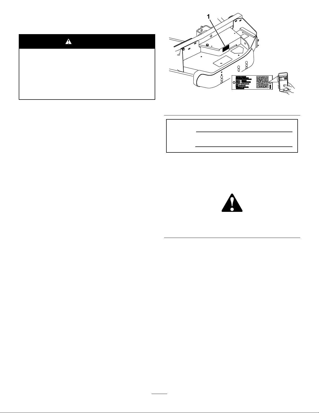
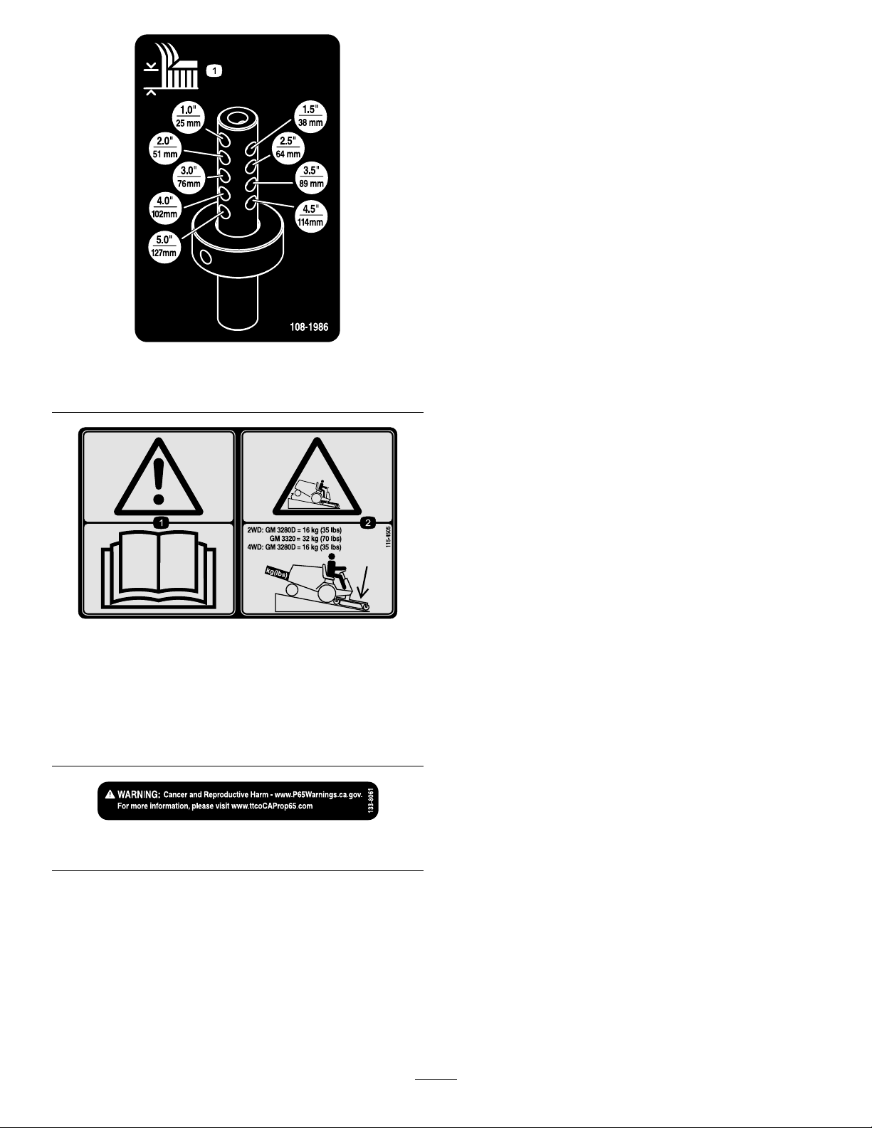
SafetyandInstructionalDecals..........................5
Setup........................................................................7
1PreparingtheMachine.....................................7
2InstallingaCompletionKit................................7
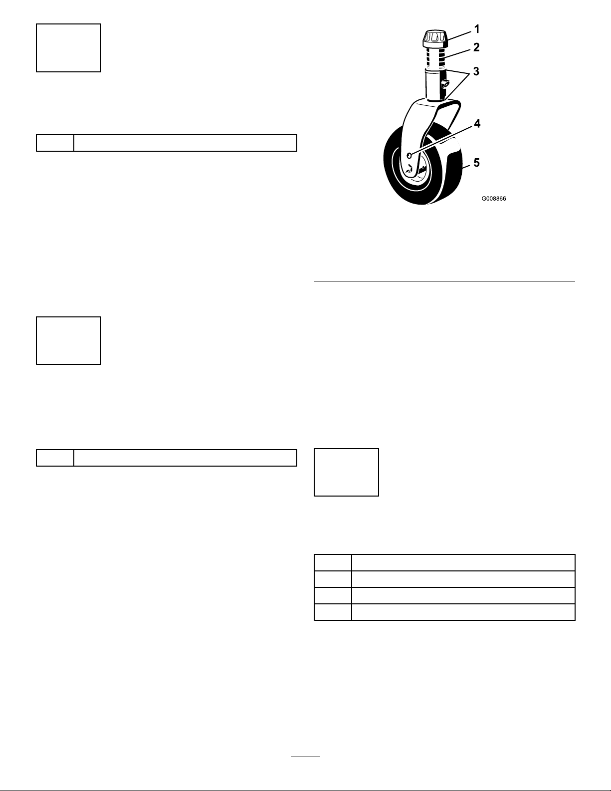
3InstallingtheCastorWheelAssemblies............8
4InstallingtheLiftArms......................................8
5InstallingtheCuttingUnitsontheLift
Arms...............................................................9
6ConnectingthePTOShafttotheCutting
UnitGearbox.................................................10
7GreasingtheMachine....................................10
ProductOverview....................................................11
Specications...................................................11
Attachments/Accessories..................................11
Operation.................................................................11
AdjustingtheHeight-of-Cut................................11
AdjustingtheCuttingUnitPitch.........................13
AdjustingtheSkids...........................................13
AdjustingtheRollers.........................................14
CorrectingCuttingUnitMismatch.....................14
OperatingTips.................................................15
Maintenance...........................................................16
RecommendedMaintenanceSchedule(s)...........16
DailyMaintenanceChecklist.............................16
Lubrication........................................................17
CheckingtheLubricantintheGearbox..............17
SeparatingtheCuttingUnitfromtheTraction
Unit...............................................................18
MountingtheCuttingUnittotheTraction
Unit...............................................................19
ServicingtheBushingsintheCastor
Arms.............................................................19
ServicingtheCastorWheelsand
Bearings........................................................20
ServicingtheCuttingBlades.............................20
CheckingandCorrectingMismatchof
Blades...........................................................22
ReplacingtheDriveBelt...................................22
CleaningUndertheCuttingUnit........................23
Storage...................................................................23
Safety
Thismachinehasbeendesignedinaccordancewith
ENISO5395:2013andANSIB71.4-2017.
GeneralSafety
Thisproductiscapableofamputatinghandsand
feetandofthrowingobjects.Alwaysfollowallsafety
instructionstoavoidseriouspersonalinjury.
•Readandunderstandthecontentsofthis
Operator’sManualbeforestartingtheengine.
•Useyourfullattentionwhileoperatingthe
machine.Donotengageinanyactivitythat
causesdistractions;otherwise,injuryorproperty
damagemayoccur.
•Donotputyourhandsorfeetnearmoving
componentsofthemachine.
•Donotoperatethemachinewithoutallguards
andothersafetyprotectivedevicesinplaceand
workingonthemachine.
•Keepclearofanydischargeopening.Keep
bystandersandpetsawayfromthemachine.
•Keepchildrenoutoftheoperatingarea.Never
allowchildrentooperatethemachine.
•Parkthemachineonalevelsurface,lowerthe
cuttingunits,disengagethedrives,engagethe
parkingbrake(ifprovided),shutofftheengine,
andremovethekeybeforeleavingtheoperator's
positionforanyreason.
Improperlyusingormaintainingthismachinecan
resultininjury.Toreducethepotentialforinjury,
complywiththesesafetyinstructionsandalways
payattentiontothesafety-alertsymbol,which
meansCaution,Warning,orDanger—personalsafety
instruction.Failuretocomplywiththeseinstructions
mayresultinpersonalinjuryordeath.
Youcanndadditionalsafetyinformationwhere
neededthroughoutthisOperator’sManual.
CuttingUnitSafety
•Thecuttingunitisonlyapartofacomplete
machinewheninstalledonatractionunit.Read
thetractionunitOperator’sManualcarefully
forcompleteinstructionsonthesafeuseofthe
machine.
•Stopthemachine,removethekey,andwaitfor
allmovingpartstostopbeforeinspectingthe
attachmentafterstrikinganobjectorifthereis
anabnormalvibrationinthemachine.Makeall
necessaryrepairsbeforeresumingoperation.
3

•Keepallpartsingoodworkingconditionandall
hardwaretightened.Replaceallwornordamaged
decals.
•Useonlyaccessories,attachments,and
replacementpartsapprovedbyToro.
4

SafetyandInstructionalDecals
Safetydecalsandinstructionsareeasilyvisibletotheoperatorandarelocatednearanyarea
ofpotentialdanger.Replaceanydecalthatisdamagedormissing.
decal120-6604
120-6604
1.Thrownobjecthazard—keepbystandersawayfromthe
machine.
2.Cutting/dismembermenthazardofhand,mower
blade—stayawayfrommovingparts,keepallguardsand
shieldsinplace.
3.Cutting/dismembermenthazardoffoot,mowerblade—stay
awayfrommovingparts,keepallguardsandshieldsin
place.
decal93-6697
93-6697
1.ReadtheOperator's
Manual.
2.AddSAE80w-90(API
GL-5)oilevery50hours.
decal93-7818
93-7818
1.Warning—readtheOperator'sManualforinstructionson
torquingthebladebolt/nutto115to149N∙m(85to110
ft-lb).
decal117-4979
117–4979
1.Entanglementhazard,belt—stayawayfrommovingparts,
keepallguardsandshieldsinplace.
decal108-1988
108-1988
1.Beltrouting
decal100-5622
100-5622
1.Height-of-cutadjustment
5

decal108-1986
108-1986
1.Heightofcut
decal115-4505
115-4505
1.Warning—readtheOperator'sManual.
2.Tippinghazard—lowerthecuttingunitwhendrivingdown
slopes.For2wheeldriveunits,adda16kg(35lb)rear
weighttoGM3280Dunitsanda32kg(70lb)rearweightto
GM3320units.For4wheeldrive3280Dunits,adda16
kg(35lb)rearweight.
decal133-8061
133-8061
6

Setup
LooseParts
Usethechartbelowtoverifythatallpartshavebeenshipped.
ProcedureDescriptionQty.Use
1Nopartsrequired–Preparethemachine.
2Completionkit(soldseparately)1Installacompletionkit.
3Castorwheelassembly2Installthecastorwheelassemblies.
Rightliftarm1
Leftliftarm1
Pivotpin2
4Cotterpin2
Installtheliftarms.
Thrustwasher4
Clevispin4
Hairpincotter2
Height-of-cutcollar2
Clevispin2
Hairpincotter2
Bolt(1/2x3/4inch)2
5
Washer2
Installthecuttingunits
6Nopartsrequired–ConnectthePTOshafttothecutting
unitgearbox.
7Nopartsrequired–Greasethemachine.
MediaandAdditionalParts
DescriptionQty.Use
PartsCatalog1
Operator'sManual1Readmaterialbeforeoperation
WARNING
Ifyouleavethekeyintheignitionswitch,
someonecouldaccidentallystarttheengine
andseriouslyinjureyouorotherbystanders.
Removethekeyfromtheignitionswitch
beforeyoudoanymaintenance.
DANGER
IftheengineisstartedandthePTOshaftis
allowedtorotate,seriousinjurycouldresult.
DonotstarttheengineandengagethePTO
leverwhenthePTOshaftisnotconnectedto
thegearboxonthecuttingunit.
Note:Determinetheleftandrightsidesofthe
machinefromthenormaloperatingposition.
1
PreparingtheMachine
NoPartsRequired
Procedure
1.Parkthemachineonalevelsurface.
2.Engagetheparkingbrake.
3.Shutofftheengineandremovethekey.
7

2
InstallingaCompletionKit
Partsneededforthisprocedure:
1Completionkit(soldseparately)
Procedure
Install1ofthefollowing62-inchor72-inchcompletion
kitstothebasedeckusingtheinstructionprovided
inthekit:
•Model30303,72-inchRearDischarge
•Model30304,72-inchGuardian
•Model30305,62-inchRearDischarge
•Model30306,62-inchGuardian
3
InstallingtheCastorWheel
Assemblies
Partsneededforthisprocedure:
2Castorwheelassembly
Procedure
Thethrustwashers,spacers,andtensioningcaps
havebeeninstalledonthecastorwheelspindlesfor
shipping.
1.Removethetensioningcapsfromthespindle
shaftsandslideoffthespacersandthrust
washers(Figure3).
g008866
Figure3
1.Tensioningcap4.Axlemountingholes
2.Spacers5.Castorwheel
3.Thrustwashers
2.Slidethespacersontothecastorspindleto
getthedesiredheight-of-cut;refertoFigure7
andFigure8todeterminethecombinationsof
spacersforthesetting.Slideathrustwasher
ontothespindle,pushthecastorthroughthe
castorarm.Installanotherthrustwasherand
theremainingspacersontothespindleand
installthetensioningcaptosecuretheassembly
(Figure3).
Important:Thethrustwashers,notthe
spacers,mustcontactthetopandbottom
ofthecastorarm.
4
InstallingtheLiftArms
Partsneededforthisprocedure:
1Rightliftarm
1Leftliftarm
2Pivotpin
2Cotterpin
Procedure
1.On1sideofthetractionunit,loosen(donot
remove)thewheelnutssecuringthewheeland
tireassemblytothefrontwheelstuds.
2.Jackupthemachineuntilthefrontwheelisoffof
theoor.Usejackstandsorblockthemachine
topreventitfromaccidentallyfalling.
8

3.Removethewheelnutsandslidethewheeland
tireassemblyoffofthestuds.
4.Mountaliftarmtothepivotbracketwithapivot
pinandacotterpin(Figure4).Mounttheliftarm
withthebendpositionedoutward.
g012393
Figure4
1.Pivotpin3.Pivotbracket
2.Liftarm4.Brakereturnspring
5.Hookthebrakereturnspringtothetabonthe
liftarm(Figure4).
6.Installthewheelandtireassembly.Torquethe
wheelnutsto102to108N·m(75to80ft-lb).
7.Repeattheprocedureontheoppositesideof
themachine.
5
InstallingtheCuttingUnits
ontheLiftArms
Partsneededforthisprocedure:
4Thrustwasher
4Clevispin
2Hairpincotter
2Height-of-cutcollar
2Clevispin
2Hairpincotter
2Bolt(1/2x3/4inch)
2Washer
Procedure
1.Movethecuttingunitintopositioninfrontofthe
tractionunit.
2.MovetheliftlevertotheFLOATposition.Push
aliftarmdownuntiltheholesintheliftarmline
upwiththeholesinthecastorarmbracketand
theheightofcutrodcanbeinsertedintothelift
armpads(Figure5).
3.Securetheliftarmtothecastorarmwith2
thrustwashers,aclevispinandahairpincotter.
Positionthethrustwashersbetweentheliftarm
andthecastorarmbracket(Figure5).Insert
endofcotterpinintotheslotinthecastorarm
tabtoretaincotterpin.
g012229
Figure5
1.Liftarm7.Hairpincotter
2.Castorarmbracket8.Height-of-cutcollar
3.Height-of-cutrod9.Clevispin
4.Liftarmpads10.Hairpincotter
5.Thrustwashers11.Bolt
6.Clevispin
4.Repeattheprocedureontheoppositeliftarm.
5.Startthetractionunitandraisethecuttingunit.
6.Pushdownontherearofthecuttingunitand
inserttheheightofcutrodsthroughtheliftarm
pads.
9

7.Installtheheightofcutcollarsontotheheight
ofcutrodsandsecurewiththeclevispinsand
hairpincotters(Figure5).Positiontheheadof
theclevispintowardthefrontofthedeck,if
possible.
8.Installabolt(1/2x3/4inch)andawashertotop
ofeachheightofcutrod(Figure5).
6
ConnectingthePTOShaft
totheCuttingUnitGearbox
NoPartsRequired
Procedure
1.SlidethemalePTOshaftintothefemalePTO
shaft(Figure6).Alignthemountingholesinthe
gearcaseinputshaftwiththeholesinthePTO
shaftandslidethemtogether.
g012230
Figure6
1.PTOshaft3.Gearcase
2.Boltsandlocknuts4.Rollpin
2.Securethemwitharollpin(Figure6).
3.Tightentheboltsandnuts(Figure6).
7
GreasingtheMachine
NoPartsRequired
Procedure
Beforeoperatingthemachine,itmustbegreasedto
ensureproperlubricatingcharacteristics;referto7
GreasingtheMachine(page10).Failuretoproperly
greasethemachinewillresultinprematurefailureof
criticalparts.
10

ProductOverview
Specications
Note:Specicationsanddesignaresubjectto
changewithoutnotice.
Width
ofCut
1.575m(62inches)or1.829m(72inches)
Height
ofCut
Adjustablefrom25to127mm(1to5inches)in13
mm(1/2inch)increments
Net
Weight
Model30403–190kg(420lbs.)
Model30404–231kg(510lbs.)
Attachments/Accessories
AselectionofT oroapprovedattachmentsand
accessoriesisavailableforusewiththemachine
toenhanceandexpanditscapabilities.Contact
yourAuthorizedServiceDealerorauthorizedToro
distributororgotowww.T oro.comforalistofall
approvedattachmentsandaccessories.
Toensureoptimumperformanceandcontinuedsafety
certicationofthemachine,useonlygenuineT oro
replacementpartsandaccessories.Replacement
partsandaccessoriesmadebyothermanufacturers
couldbedangerous,andsuchusecouldvoidthe
productwarranty.
Operation
Note:Determinetheleftandrightsidesofthe
machinefromthenormaloperatingposition.
CAUTION
Ifyouleavethekeyintheignitionswitch,
someonecouldaccidentlystarttheengine
andseriouslyinjureyouorotherbystanders.
Removethekeyfromtheignitionbeforeyou
doanymaintenance.
AdjustingtheHeight-of-Cut
Theheight-of-cutisadjustablefrom25to127mm(1
to5inches)in13mm(1/2inch)increments.Toadjust
theheight-of-cut,positionthecastorwheelaxlesin
theupperorlowerholesofthecastorforks,addor
removeanequalnumberofspacersfromthecastor
forksandsecuretheheightofcutcollartothedesired
holesintheheightofcutrod.
1.Starttheengineandraisethecuttingunitoffthe
oorsothatyoucanchangetheheight-of-cut.
Shutofftheengineandremovethekeyafter
youraisethecuttingunit.
2.Positionthecastorwheelaxlesinthesame
holesinbothcastorforks.RefertoFigure7and
Figure8todeterminethecorrectholesforthe
setting.
Note:Whenoperatingin64mm(2–1/2inches)
heightofcutorhigher,installtheaxleboltinthe
lowercastorforkholetopreventgrassbuildup
betweenthewheelandthefork.Whenoperating
inheightofcutslowerthan64mm(2–1/2
inches)andthereisgrassbuildup,reversethe
machinesdirectiontopullanyclippingsaway
fromthewheel/forkarea.
3.Removethetensioningcapfromthespindle
shaft(Figure7)andslidethespindleoutofthe
castorarm.Putthe2shims(1/8inch)ontothe
spindleshaftastheywereoriginallyinstalled.
Theseshimsarerequiredtoachievealevel
acrosstheentirewidthofthecuttingunits.Slide
theappropriatenumberof1/2inchspacersonto
thespindleshafttogetthedesiredheight-of-cut;
thenslidethewasherontotheshaft.
RefertoFigure7andFigure8todeterminethe
combinationsofspacersforthesetting.
11

g008866
Figure7
1.Tensioningcap4.Axlemountingholes
2.Spacers5.Castorwheel
3.Shims
decal100-5622
Figure8
4.Pushthecastorspindlethroughthecastor
arm.Installtheshims(astheywereoriginally
installed)andtheremainingspacersontothe
spindleshaft.Installthetensioningcapto
securetheassembly.
5.Removethehairpinandclevispinsecuringthe
heightofcutcollartotheheightofcutrodonthe
rearofthecuttingunit(Figure9).
g012231
Figure9
1.Height-of-cutrod3.Clevispinandhairpin
cotter
2.Height-of-cutcollar
6.Aligntheheight-of-cutcollartothedesired
height-of-cutholesontheheight-of-cutrod
(Figure10).
decal108-1986
Figure10
7.Securetheadjustmentwiththeclevispinand
hairpin.
Note:Positiontheheadoftheclevispintoward
thefrontofthedeck,ifpossible.
Note:Whenusing25mm(1inch),38mm
(1-1/2inch),oroccasionally51mm(2inch)
height-of-cut,movetheskidsandrollertothe
highestholes.
12

AdjustingtheCuttingUnit
Pitch
Cuttingunitpitchisthedifferenceinheight-of-cutfrom
thefrontofthebladeplanetothebackoftheblade
plane.Useabladepitchof6mm(1/4inch).Thatis
thebackofthebladeplaneis6mm(1/4inch)higher
thanthefront.
1.Parkthemachineonalevelsurface.
2.Engagetheparkingbrake.
3.Shutofftheengineandremovethekey.
4.Setthecuttingunittothedesiredheight-of-cut.
5.Rotate1bladesothatitpointsstraightforward.
6.Usingashortruler,measurefromtheoorto
thefronttipoftheblade.Rotatethebladetipto
therearandmeasurefromtheoortothetip
oftheblade.
7.Subtractthefrontdimensionfromtherear
dimensiontocalculatethebladepitch.
8.Loosenthejamnutsonthebottomofthe
height-of-cutrods(Figure11).
g012232
Figure11
1.Height-of-cut2.Jamnut
9.Rotatetheheight-of-cutrodstoraiseorlower
therearofthecuttingunitandattainthecorrect
cuttingunitpitch.
10.Tightenthejamnuts.
AdjustingtheSkids
Mounttheskidsinthelowerpositionwhenoperating
inheightofcutshigherthan64mm(2-1/2inches)and
inthehigherpositionwhenoperatinginheightofcuts
lowerthan64mm(2-1/2inches).
Note:Whentheskidsbecomeworn,youcanswitch
theskidtotheoppositesidesofthemower,ipping
themover.Thiswillallowyoutousetheskidslonger
beforereplacingthem.
1.DisengagethePTOandengagetheparking
brake.
2.Shutofftheengine,removethekey,andwait
forallmovingpartstostopbeforeleavingthe
operatingposition.
3.Loosenthescrewatthefrontofeachskid
(Figure12).
4.Removetheange-headboltsandnutsfrom
eachskid.
5.Moveeachskidtothedesiredpositionand
securethemwiththeange-headboltsandnuts
(Figure12).
Note:Onlyusethetoporcentersetsofholes
toadjusttheskids.Thebottomholesareused
whenswitchingsidesonaGuardianmower,at
whichtimetheybecomethetopholesonthe
othersideofthemower.
g268888
Figure12
1.Screw3.Skid
2.Flange-headbolt4.Nut
6.Torquethescrewatthefrontofeachskidto9to
11N⋅m(80to100in-lb).
13

AdjustingtheRollers
Note:Ifthecuttingunitistobeusedinthe25or38
mm(1or1-1/2inch)height-of-cutsetting,positionthe
cuttingunitrollersinthetopbracketholes.
1.Removethescrewandnutsecuringtheroller
shafttothedeckbracket(Figure13).
g004487
Figure13
1.Roller2.Rollershaft
2.Slidetheshaftoutofthelowerbracketholes,
aligntherollerwiththetopholes,andinstallthe
shaft.
3.Installthescrewandnuttosecurethe
assemblies.
CorrectingCuttingUnit
Mismatch
Duetodifferencesingrassconditionsandthe
counterbalancesettingofthetractionunit,itisadvised
thatgrassbecutandappearancecheckedbefore
formalcuttingisstarted.
1.Setthecuttingunittothedesiredheightofcut;
refertoAdjustingtheHeight-of-Cut(page11).
2.Checkandadjustfrontandreartractortire
pressureto172to207kPa(25to30psi).
3.Checkandadjustallcastortirepressuresto345
kPa(50psi).
4.Checkforbentblades;refertoCheckingfora
BentBlade(page20).
5.Cutgrassinatestareatodetermineifallcutting
unitsarecuttingatthesameheight.
6.Ifcuttingunitadjustmentsarestillneeded,nda
atsurfaceusinga2m(6ft)orlongerstraight
edge.
7.Toeasemeasuringbladeplane,raisetheheight
ofcuttothehighestposition;refertoAdjusting
theHeight-of-Cut(page11).
8.Lowercuttingunitontotheatsurface.Remove
thecoversfromthetopofthecuttingunits.
9.Rotatethebladeoneachspindleuntiltheends
faceforwardandbackward.
10.Measurefromtheoortothefronttipofthe
cuttingedge.
11.Adjust1/8inchshimsoncastorfork(s)tomatch
heightofcuttodecal(Figure14);referto
AdjustingtheCuttingUnitPitch(page13).
g008866
Figure14
1.Tensioningcap4.Axlemountingholes
2.Spacers5.Castorwheel
3.Shims
14

OperatingTips
FastThrottleSetting/Ground
Speed
Tomaintainenoughpowerforthemachineanddeck
whilemowing,operatetheengineatthefastthrottle
positionandadjustyourgroundspeedforconditions.
Decreasethegroundspeedastheloadonthecutting
bladesincreases.Increasethegroundspeedasthe
loadonthebladesdecreases.
MowingDirection
Alternatemowingdirectiontoavoidmakingrutsin
theturfovertime.Thisalsohelpsdisperseclippings
whichenhancesdecompositionandfertilization.
CuttingSpeed
Toimprovecutquality,useaslowergroundspeed.
AvoidCuttingTooLow
Ifthecuttingwidthofthecuttingunitiswiderthanthe
moweryoupreviouslyused,raisethecuttingheightto
ensurethatuneventurfisnotcuttooshort.
SelecttheProperHeight-of-Cut
SettingtoSuitConditions
Removeapproximately1inch(25mm)orno
morethan1/3ofthegrassbladewhencutting.In
exceptionallylushanddensegrass,youmayhave
toslowdowntheforwardspeedand/orraisethe
height-of-cuttothenexthighersetting.
Important:Ifcuttingmorethan1/3ofthe
grassbladeoff,orinsparselonggrassor
dryconditions,theuseofatsailbladesis
recommendedtoreduceair-bornechaff,debris,
anddeckdrivecomponentstrain.
LongGrass
Ifthegrassiseverallowedtogrowslightlylongerthan
normal,orifitcontainsahighdegreeofmoisture,
raisethecuttingheighthigherthanusualandcutthe
grassatthissetting.Thencutthegrassagainusing
thelower,normalsetting.
KeeptheCuttingUnitClean
Cleanclippingsanddirtfromtheundersideofthe
cuttingunitaftereachuse.Ifgrassanddirtbuildup
insidethecuttingunit,cuttingqualitywilleventually
becomeunsatisfactory.
Toreducetheriskofrehazard,keeptheengine,
mufer,batterycompartment,parkingbrake,cutting
units,andfuelstoragecompartmentfreeofgrass,
leaves,orexcessivegrease.Cleanupanyspilledoil
orfuel.
BladeMaintenance
Maintainasharpbladethroughoutthecuttingseason
becauseasharpbladecutscleanlywithouttearingor
shreddingthegrassblades.T earingandshredding
turnsgrassbrownattheedges,whichslowsgrowth
andincreasesthechanceofdisease.Checkthe
bladesdailyforsharpness,andforanywearor
damage.Sharpenthebladesasnecessary.Ifablade
isdamagedorworn,replaceitimmediatelywitha
genuineTororeplacementblade.RefertoServicing
theCuttingBlades(page20).
SettingtheCuttingUnitPitch
Werecommendabladepitchof8mm(5/16inch).A
pitchlargerthan8mm(5/16inch)willresultinless
powerrequired,largerclippings,andapoorerquality
ofcut.Apitchlessthan8mm(5/16inch)willresultin
morepowerrequired,smallerclippingsandabetter
qualityofcut.
15

Maintenance
Note:Determinetheleftandrightsidesofthe
machinefromthenormaloperatingposition.
RecommendedMaintenanceSchedule(s)
MaintenanceService
IntervalMaintenanceProcedure
Aftertherst2hours•Tightenthecastorwheelnuts.
Aftertherst10hours•Tightenthecastorwheelnuts.
•Torquethebladebolts.
Beforeeachuseordaily
•Lubricatethecastorarmbushings.
•Lubricatethecastorwheelbearings.
•Checktheblades.
•Cleanthecuttingunit.
Every50hours
•Lubricatethegreasettings.Lubricatethegreasettingsimmediatelyafterevery
washing.
•Checkthegearboxlubricant.
•Tightenthecastorwheelnuts.
•Torquethebladebolts.
•Checkthebladedrivebeltadjustment.
•Cleanunderthecuttingunitbeltcovers.
Every400hours•Changethegearboxlubricant.
DailyMaintenanceChecklist
Duplicatethispageforroutineuse.
Fortheweekof: MaintenanceCheckItem
Mon.Tues.Wed.Thurs.Fri.Sat.Sun.
CheckGrassDeectorin
DownPosition(ifapplicable)
CheckTirePressure
CheckConditionofBlades
LubricateAllGreaseFittings1
Touch-upDamagedPaint
1.Immediatelyaftereverywashing,regardlessoftheintervallisted.
NotationforAreasofConcern
Inspectionperformedby:
ItemDateInformation
16

CAUTION
Ifyouleavethekeyintheignitionswitch,someonecouldaccidentlystarttheengineand
seriouslyinjureyouorotherbystanders.
Removethekeyfromtheignitionbeforeyoudoanymaintenance.
Important:Thefastenersonthecoversofthismachinearedesignedtoremainonthecoverafter
removal.Loosenallthefastenersoneachcoverafewturnssothatthecoverisloosebutstillattached,
thengobackandloosenthemuntilthecovercomesfree.Thispreventsyoufromaccidentallystripping
theboltsfreeoftheretainers.
Lubrication
ServiceInterval:Every50hoursLubricatethe
greasettingsimmediatelyafter
everywashing.
Themachinehasgreasettingsthatyoumust
lubricateregularlywithNo.2lithiumgrease.
Lubricatethefollowingareas:
•Castorforkshaftbushings(4)(Figure15).
g011557
Figure15
•Spindleshaftbearings(3)(locatedunderthe
pulley)(Figure16)
g012234
Figure16
•Idlerarmshaftbearings(Figure16)
•Liftarmpivots,front(2)(Figure17)
g012235
Figure17
1.Liftarm3.Hairpincotter
2.Clevispin4.Pivotsupport
•Liftarmpivots,rear(2)(Figure18)
g010550
Figure18
CheckingtheLubricantin
theGearbox
ServiceInterval:Every50hours
ThegearboxindesignedtooperateonSAE80–90
weightgearlube.Althoughthegearboxcomeswith
lubricantfromthefactory,checkthelevelbefore
operatingthecuttingunit.Thegearboxcapacityis
283ml(12oz).
1.Parkthemachineandcuttingunitonalevel
surface.
17

2.Removethedipstick/llplugfromthetopof
thegearbox(Figure19)andensurethatthe
lubricantisbetweenthemarksonthedipstick.If
thelubricantlevelislow,addenoughlubricant
untilthelevelisbetweenthemarks.
g010548
Figure19
1.Dipstick/llplug
SeparatingtheCuttingUnit
fromtheTractionUnit
1.Positionthemachineonlevelsurface,lowerthe
cuttingunittotheoor,movetheliftlevertothe
Floatposition,shuttheengineoff,andengage
theparkingbrake.
2.Removetheboltandwashermountedtothetop
ofeachheightofcutrod(Figure20).
g012236
Figure20
1.Height-of-cutrod3.Height-of-cutcollar
2.Boltandwasher4.Hairpincotterandclevis
pin
3.Removethehairpinandclevispinsecuringthe
heightofcutcollartotheheightofcutrodon
therearofthecuttingunit(Figure20).Remove
theheightofcutcollar.
4.Removethehairpincottersandclevispins
securingtheliftarmstothecastorarmbrackets
(Figure21).
g012237
Figure21
1.Liftarm3.Hairpincotter
2.Clevispin4.Castorarmbracket
5.Rollthecuttingunitawayfromthetractionunit,
separatingthemaleandfemalesectionsofthe
PTOshaft(Figure22).
g010552
Figure22
1.PTOshaft
DANGER
IftheengineisstartedandthePTOshaft
isallowedtorotate,seriousinjurycould
result.
Donotstarttheengineandengagethe
PTOleverwhenthePTOshaftisnot
connectedtothegearboxonthecutting
unit.
18

MountingtheCuttingUnit
totheTractionUnit
1.Positionthemachineonalevelsurfaceandshut
theengineoff.
2.Movethecuttingunitintopositioninfrontofthe
tractionunit.
3.SlidethemalePTOshaftintothefemalePTO
shaft(Figure22).
4.MovetheliftlevertotheFLOATposition.Push
aliftarmdownuntiltheholesintheliftarmline
upwiththeholesinthecastorarmbracketand
youcaninserttheheight-of-cutrodintothelift
armpads(Figure23).
g012229
Figure23
1.Liftarm7.Hairpincotter
2.Castorarmbracket8.Height-of-cutcollar
3.Height-of-cutrod9.Clevispin
4.Liftarmpads10.Hairpincotter
5.Thrustwashers11.Bolt
6.Clevispin
5.Securetheliftarmtothecastorarmwith2
thrustwashers,aclevispinandahairpincotter.
Positionthethrustwashersbetweentheliftarm
andthecastorarmbracket(Figure23).Insert
endofcotterpinintotheslotinthecastorarm
tabtoretaincotterpin.
6.Repeattheprocedureontheoppositeliftarm.
7.Startthetractionunitandraisethecuttingunit.
8.Pushdownontherearofthecuttingunitand
inserttheheightofcutrodsthroughtheliftarm
pads.
9.Installtheheight-of-cutcollarsontothe
height-of-cutrodsandsecurewiththeclevis
pinsandhairpincotters(Figure23).
Positiontheheadoftheclevispintowardthe
frontofthedeck.
10.Installabolt(1/2x3/4inch)andawashertothe
topofeachheight-of-cutrod(Figure23).
ServicingtheBushingsin
theCastorArms
Thecastorarmshavebushingspressedintothe
topandbottomofthetube,andaftermanyhours
ofoperation,thebushingswillwear.T ocheckthe
bushings,movethecastorforkbackandforthand
fromsidetoside.Ifthecastorspindleislooseinside
thebushings,thebushingsarewornandmustbe
replaced.
1.Raisethecuttingunitsothatthewheelsare
offoftheoor.Blockthecuttingunitsothatit
cannotaccidentallyfall.
2.Removethetensioningcap,spacer(s),and
thrustwasherfromthetopofthecastorspindle.
3.Pullthecastorspindleoutofthemountingtube.
Allowthethrustwasherandspacer(s)toremain
onthebottomofthespindle.
4.Insertapinpunchintothetoporbottomofthe
mountingtubeanddrivethebushingoutofthe
tube(Figure24).Also,drivetheotherbushing
outofthetube.Cleantheinsideofthetubes
toremovedirt.
g004737
Figure24
1.Castorarmtube2.Bushings
19

5.Applygreasetotheinsideandoutsideofthe
newbushings.Usingahammerandatplate,
drivethebushingsintothemountingtube.
6.Inspectthecastorspindleforwearandreplace
itifdamaged.
7.Pushthecastorspindlethroughthebushings
andmountingtube,slidethethrustwasher
andspacer(s)ontothespindle,andinstallthe
tensioningcaponthecastorspindle.
ServicingtheCastor
WheelsandBearings
1.Removethelocknutfromtheboltholdingthe
castorwheelassemblybetweenthecastorfork
().Graspthecastorwheelandslidetheboltout
oftheforkorpivotarm.
g004738
Figure25
1.Castorwheel3.Bearing(2)
2.Castorfork4.Bearingspacer
2.Removethebearingfromthewheelhuband
allowthebearingspacertofallout().Remove
thebearingfromtheoppositesideofthewheel
hub.
3.Checkthebearings,spacer,andinsideofthe
wheelhubforwear.Replaceanydamaged
parts.
4.Toassemblethecastorwheel,pushthebearing
intothewheelhub.Wheninstallingthebearings,
pressontheouterraceofthebearing.
5.Slidethebearingspacerintothewheelhub.
Pushtheotherbearingintotheopenendofthe
wheelhubtocaptivatethebearingspacerinside
thewheelhub.
6.Installthecastorwheelassemblybetweenthe
castorforkandsecureitinplacewiththebolt
andlocknut.
ServicingtheCutting
Blades
BladeSafety
Awornordamagedbladecanbreak,andapieceof
thebladecouldbethrowntowardyouorbystanders,
resultinginseriouspersonalinjuryordeath.
•Inspectthebladeperiodicallyforwearordamage.
•Usecarewhencheckingtheblades.Wrapthe
bladesorweargloves,andusecautionwhen
servicingtheblades.Onlyreplaceorsharpenthe
blades;neverstraightenorweldthem.
•Onmulti-bladedmachines,takecareasrotating1
bladecancauseotherbladestorotate.
CheckingforaBentBlade
1.Positionthemachineonalevelsurface.Raise
thecuttingunit,engagetheparkingbrake,put
thetractionpedalinneutral,putthePTOlever
intheOFFposition,shutofftheengine,and
removetheignitionkey.Blockthecuttingunitto
preventitfromaccidentallyfalling.
2.Rotatethebladeuntiltheendsfaceforward
andbackward.Measurefromtheinsideofthe
cuttingunittothecuttingedgeatthefrontofthe
blade(Figure26),andrememberthisdimension.
g010549
Figure26
3.Rotatetheoppositeendofthebladeforward.
Measurebetweenthecuttingunitandcutting
edgeofthebladeatthesamepositionasin
step2Thedifferencebetweenthedimensions
obtainedinsteps2and3mustnotexceed3
mm(1/8inch).Ifthedimensionexceeds3mm
(1/8inch),replacethebladebecauseitisbent;
refertoRemovingandInstallingtheBlade(s)
(page20).
RemovingandInstallingthe
Blade(s)
Theblademustbereplacedifasolidobjectishit,
thebladeisout-of-balance,worn,orbent.Always
usegenuineTororeplacementbladestoensure
safetyandoptimumperformance.Neveruseblades
madebyothermanufacturersbecausetheycouldbe
dangerous.
20
Other manuals for 30403
2
This manual suits for next models
1
Table of contents
Other Toro Lawn Mower manuals

Toro
Toro Z Master Professional 7500-DSeries Manual

Toro
Toro Z MASTER Z557 User manual

Toro
Toro Groundsmaster 200 User manual

Toro
Toro 75951 User manual

Toro
Toro ProLine 30165 User manual

Toro
Toro TimeCutter HD MyRide User manual

Toro
Toro Super Recycler 20792 User manual

Toro
Toro 03691 User manual

Toro
Toro titan zx User manual

Toro
Toro LX466 13AT61RH044 User manual