Toro Greensmaster e1021 User manual

Form No. 3463-557 Rev A
Greensmaster
®
e1021, e1026,
and eFlex
®
1021 Greensmower
Model No. 04835 —Serial No. 400000000 and Up
Model No. 04845 —Serial No. 400000000 and Up
Model No. 04865 —Serial No. 400000000 and Up
Register at www .T oro.com.
Original Instructions (EN)
*3463-557*

This product complies with all relevant European
directives; for details, please see the separate product
specic Declaration of Conformity (DOC) sheet.
W ARNING
CALIFORNIA
Proposition 65 W arning
The power cord on this product contains
lead, a chemical known to the State
of California to cause birth defects
or other reproductive harm. W ash
hands after handling.
Battery posts, terminals, and related
accessories contain lead and lead
compounds, chemicals known to
the State of California to cause
cancer and reproductive harm. W ash
hands after handling.
Use of this product may cause exposure
to chemicals known to the State of
California to cause cancer , birth defects,
or other reproductive harm.
Introduction
This machine is a walk-behind, reel-blade lawn mower
intended to be used by professional, hired operators
in commercial applications. It is primarily designed
for cutting grass on well-maintained turf. Using this
product for purposes other than its intended use could
prove dangerous to you and bystanders.
Read this information carefully to learn how to operate
and maintain your product properly and to avoid
injury and product damage. Y ou are responsible for
operating the product properly and safely .
V isit www .T oro.com for product safety and operation
training materials, accessory information, help nding
a dealer , or to register your product.
Whenever you need service, genuine T oro parts, or
additional information, contact an Authorized Service
Dealer or T oro Customer Service and have the model
and serial numbers of your product ready . Figure 1
identies the location of the model and serial numbers
on the product. W rite the numbers in the space
provided.
Important: W ith your mobile device, you can
scan the QR code (if equipped) on the serial
number decal to access warranty , parts, and other
product information.
g271512
Figure 1
1. Model and serial number location
Model No.
Serial No.
This manual identies potential hazards and has
safety messages identied by the safety-alert symbol
(Figure 2 ), which signals a hazard that may cause
serious injury or death if you do not follow the
recommended precautions.
g000502
Figure 2
Safety-alert symbol
This manual uses 2 words to highlight information.
Important calls attention to special mechanical
information and Note emphasizes general information
worthy of special attention.
© 2024—The T oro® Company
81 1 1 L yndale A venue South
Bloomington, MN 55420
2
Contact us at www .T oro.com.
Printed in the USA
All Rights Reserved

Contents
Safety . . . . . . . . . . . . . . . . . . . . . . . . . . . . . . . . . . . . . . . . . . . . . . . . . . . . . . . . . . . . . . . . . . . . . . . 4
General Safety . . . . . . . . . . . . . . . . . . . . . . . . . . . . . . . . . . . . . . . . . . . . . . . . . . . 4
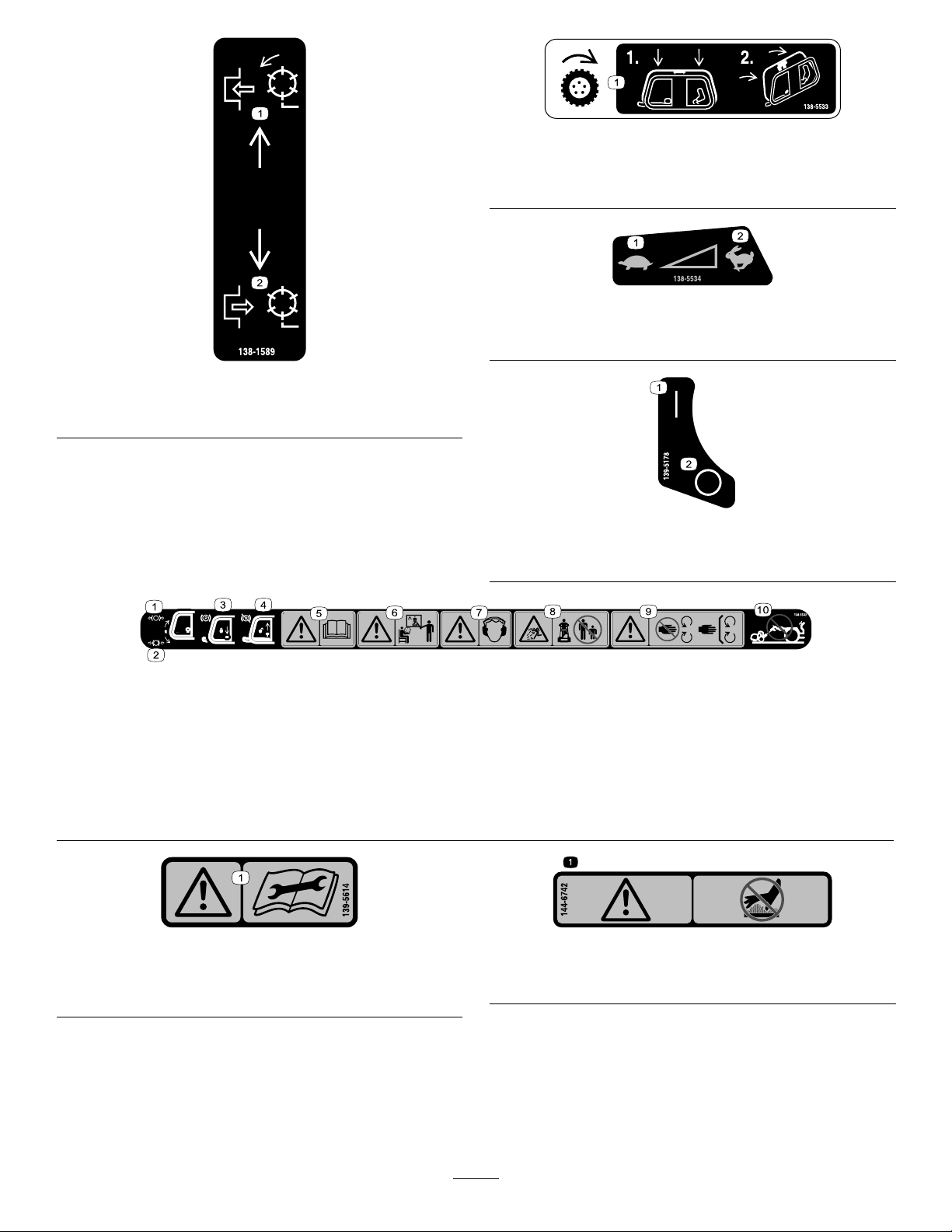
Safety and Instructional Decals . . . . . . . . . . . . . . . . . . . . . . . . . . 4
Setup . . . . . . . . . . . . . . . . . . . . . . . . . . . . . . . . . . . . . . . . . . . . . . . . . . . . . . . . . . . . . . . . . . . . . . . . 7
1 Adjusting and Installing the Cutting
Unit . . . . . . . . . . . . . . . . . . . . . . . . . . . . . . . . . . . . . . . . . . . . . . . . . . . . . . . . . . . . . . . . . 8
2 Installing the T ransport Wheels . . . . . . . . . . . . . . . . . . . . . . 10
3 Installing the Grass Basket . . . . . . . . . . . . . . . . . . . . . . . . . . . . . . 1 1
4 Adjusting the Latch Bolt for the
Handle-Height Adjuster . . . . . . . . . . . . . . . . . . . . . . . . . . . . . . . . . 12
5 Mounting the Battery Charger on a
W all . . . . . . . . . . . . . . . . . . . . . . . . . . . . . . . . . . . . . . . . . . . . . . . . . . . . . . . . . . . . . . . 12
Product Overview . . . . . . . . . . . . . . . . . . . . . . . . . . . . . . . . . . . . . . . . . . . . . . . . . . . 14
Controls . . . . . . . . . . . . . . . . . . . . . . . . . . . . . . . . . . . . . . . . . . . . . . . . . . . . . . . . . . . 15
Specications . . . . . . . . . . . . . . . . . . . . . . . . . . . . . . . . . . . . . . . . . . . . . . . . . . 17
Attachments/Accessories . . . . . . . . . . . . . . . . . . . . . . . . . . . . . . . . . 17
Before Operation . . . . . . . . . . . . . . . . . . . . . . . . . . . . . . . . . . . . . . . . . . . . . . . . . 18
Before Operation Safety . . . . . . . . . . . . . . . . . . . . . . . . . . . . . . . . . . . 18
Performing Daily Maintenance . . . . . . . . . . . . . . . . . . . . . . . . . . 18
Adjusting the Clip Rate . . . . . . . . . . . . . . . . . . . . . . . . . . . . . . . . . . . . . 18
Adjusting the Reel Speed . . . . . . . . . . . . . . . . . . . . . . . . . . . . . . . . . 18
Adjusting the T raction-Drum Position . . . . . . . . . . . . . . . . 19
Adjusting the Handle Height . . . . . . . . . . . . . . . . . . . . . . . . . . . . . 19
T ransporting the Machine to a Job
Site . . . . . . . . . . . . . . . . . . . . . . . . . . . . . . . . . . . . . . . . . . . . . . . . . . . . . . . . . . . . . . . . 19
Removing the T ransport Wheels . . . . . . . . . . . . . . . . . . . . . . . 20
During Operation . . . . . . . . . . . . . . . . . . . . . . . . . . . . . . . . . . . . . . . . . . . . . . . . . 20
During Operation Safety . . . . . . . . . . . . . . . . . . . . . . . . . . . . . . . . . . . 20
Starting the Machine . . . . . . . . . . . . . . . . . . . . . . . . . . . . . . . . . . . . . . . . . 21
Using the InfoCenter LCD Display . . . . . . . . . . . . . . . . . . . . 21
Operating T ips . . . . . . . . . . . . . . . . . . . . . . . . . . . . . . . . . . . . . . . . . . . . . . . . . . 23
Shutting Of f the Machine . . . . . . . . . . . . . . . . . . . . . . . . . . . . . . . . . . 25
After Operation . . . . . . . . . . . . . . . . . . . . . . . . . . . . . . . . . . . . . . . . . . . . . . . . . . . . 25
After Operation Safety . . . . . . . . . . . . . . . . . . . . . . . . . . . . . . . . . . . . . . 25
Operating the Controls after Mowing . . . . . . . . . . . . . . . . . 26
T ransporting the Machine . . . . . . . . . . . . . . . . . . . . . . . . . . . . . . . . . 26
Installing the T ransport Wheels . . . . . . . . . . . . . . . . . . . . . . . . . 26
Engaging or Disengaging the
T ransmission . . . . . . . . . . . . . . . . . . . . . . . . . . . . . . . . . . . . . . . . . . . . . . . . 27
Maintaining the Lithium-Ion Battery
Pack . . . . . . . . . . . . . . . . . . . . . . . . . . . . . . . . . . . . . . . . . . . . . . . . . . . . . . . . . . . . . . 27
Caring for the Battery Pack . . . . . . . . . . . . . . . . . . . . . . . . . . . . . . . 28
Understanding the Battery Charger . . . . . . . . . . . . . . . . . . 28
Maintenance . . . . . . . . . . . . . . . . . . . . . . . . . . . . . . . . . . . . . . . . . . . . . . . . . . . . . . . . . . . 30
Maintenance Safety . . . . . . . . . . . . . . . . . . . . . . . . . . . . . . . . . . . . . . . . . . 30
Recommended Maintenance Schedule(s) . . . . . . . . . . . 30
Daily Maintenance Checklist . . . . . . . . . . . . . . . . . . . . . . . . . . . . . 31
Pre-Maintenance Procedures . . . . . . . . . . . . . . . . . . . . . . . . . . . . . . 31
Preparing the Machine for Maintenance . . . . . . . . . . . . 31
Electrical System Maintenance . . . . . . . . . . . . . . . . . . . . . . . . . . . 32
Electrical System Safety . . . . . . . . . . . . . . . . . . . . . . . . . . . . . . . . . . 32
Servicing the Battery Pack . . . . . . . . . . . . . . . . . . . . . . . . . . . . . . . . 32
Disposing of the Battery . . . . . . . . . . . . . . . . . . . . . . . . . . . . . . . . . . . . 32
Maintaining the Battery Charger . . . . . . . . . . . . . . . . . . . . . . . 32
Replacing Fuses . . . . . . . . . . . . . . . . . . . . . . . . . . . . . . . . . . . . . . . . . . . . . . . 33
Acknowledging the Battery Interface
Panel ............................................................. 33
Drive System Maintenance . . . . . . . . . . . . . . . . . . . . . . . . . . . . . . . . . . 34
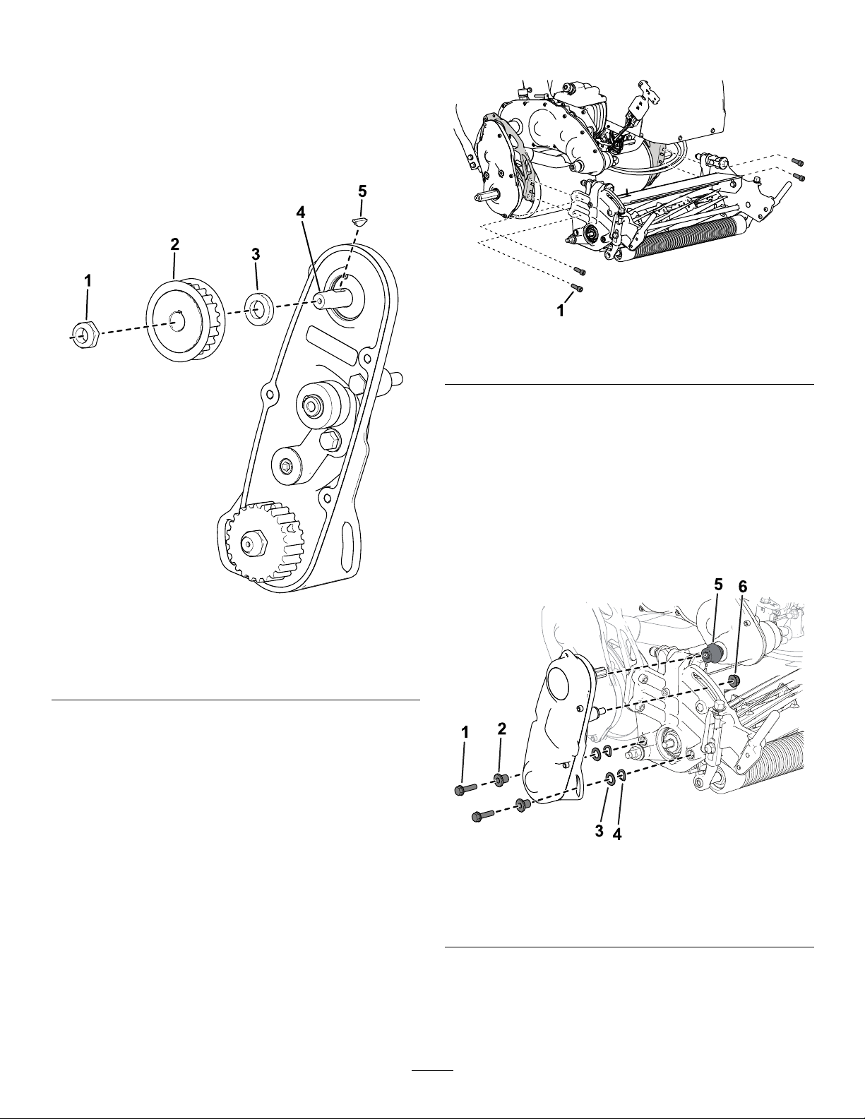
Changing the T ransmission Fluid . . . . . . . . . . . . . . . . . . . . . . 34
Controls System Maintenance . . . . . . . . . . . . . . . . . . . . . . . . . . . . . 34
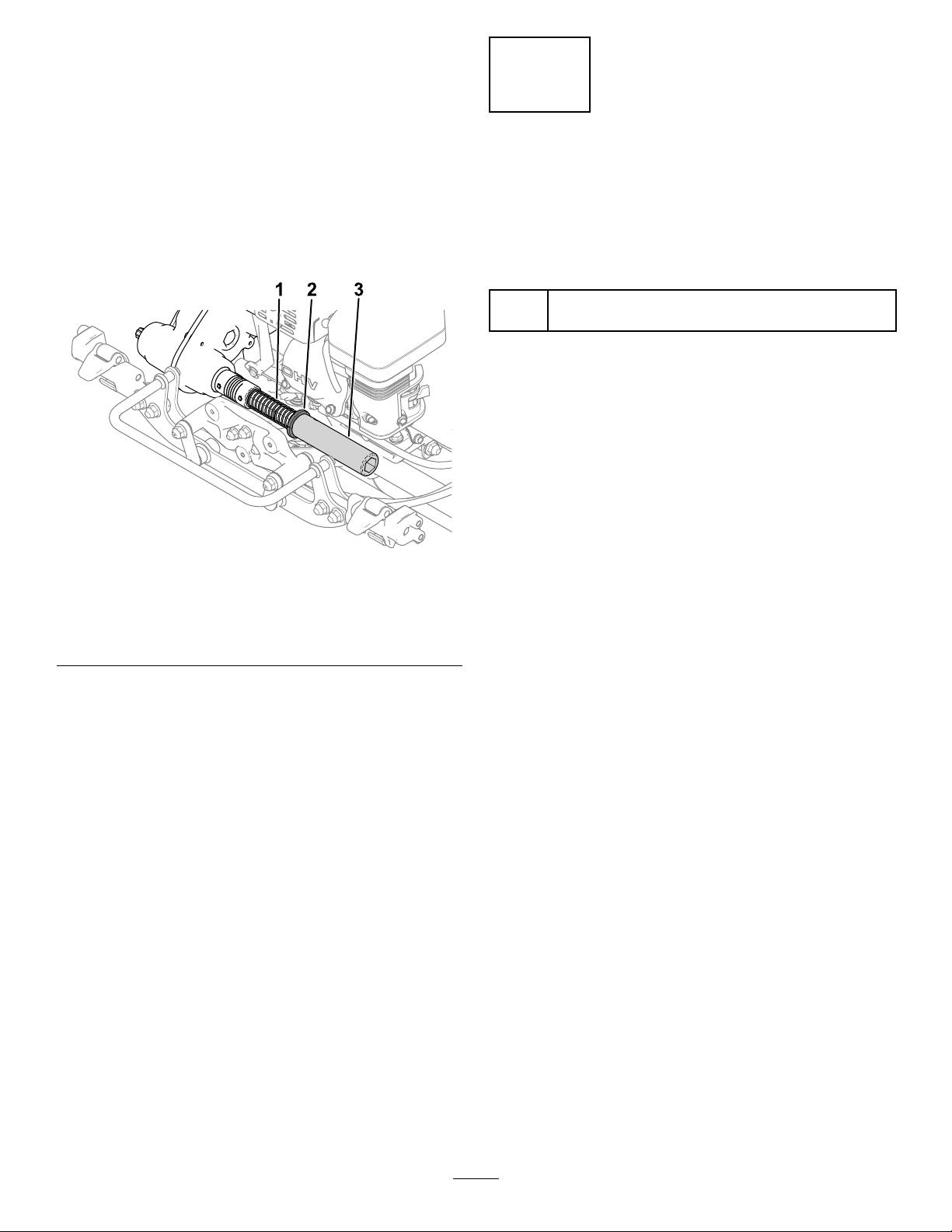
Adjusting the Service/Parking Brake . . . . . . . . . . . . . . . . . 34
Cutting Unit Maintenance . . . . . . . . . . . . . . . . . . . . . . . . . . . . . . . . . . . . . 35
Blade Safety . . . . . . . . . . . . . . . . . . . . . . . . . . . . . . . . . . . . . . . . . . . . . . . . . . . . . 35
Installing the Cutting Unit (Models 04835
and 04845) . . . . . . . . . . . . . . . . . . . . . . . . . . . . . . . . . . . . . . . . . . . . . . . . . . . . 35
Installing the Cutting Unit (Model 04865) . . . . . . . . . . . 36
Removing the Cutting Unit (Models 04835
and 04845) . . . . . . . . . . . . . . . . . . . . . . . . . . . . . . . . . . . . . . . . . . . . . . . . . . . . 36
Removing the Cutting Unit (Model
04865) . . . . . . . . . . . . . . . . . . . . . . . . . . . . . . . . . . . . . . . . . . . . . . . . . . . . . . . . . . . 37
Backlapping the Cutting Unit . . . . . . . . . . . . . . . . . . . . . . . . . . . . . 37
Cleaning . . . . . . . . . . . . . . . . . . . . . . . . . . . . . . . . . . . . . . . . . . . . . . . . . . . . . . . . . . . . . . 38
Cleaning the Machine . . . . . . . . . . . . . . . . . . . . . . . . . . . . . . . . . . . . . . . 38
Storage . . . . . . . . . . . . . . . . . . . . . . . . . . . . . . . . . . . . . . . . . . . . . . . . . . . . . . . . . . . . . . . . . . . 39
Storage Safety . . . . . . . . . . . . . . . . . . . . . . . . . . . . . . . . . . . . . . . . . . . . . . . . . . 39
Storing the Machine . . . . . . . . . . . . . . . . . . . . . . . . . . . . . . . . . . . . . . . . . . 39
Battery Storage Requirements . . . . . . . . . . . . . . . . . . . . . . . . . 39
Storing the Charger . . . . . . . . . . . . . . . . . . . . . . . . . . . . . . . . . . . . . . . . . . 39
3

Safety
General Safety
This product is capable of amputating hands and feet
and of throwing objects.
•Read and understand the contents of this
Operator ’ s Manual before starting the machine.
•Use your full attention while operating the
machine. Do not engage in any activity that
causes distractions; otherwise, injury or property
damage may occur .
•Do not put your hands or feet near moving
components of the machine.
•Do not operate the machine without all guards
and other safety protective devices in place and
functioning properly on the machine.
•Keep bystanders and children out of the operating
area. Never allow children to operate the machine.
•Park the machine on a level surface, engage the
parking brake, shut of f the machine, remove the
key (if equipped), and wait for all movement to stop
before you leave the operator ’ s position. Allow
the machine to cool before adjusting, servicing,
cleaning, or storing it.
Improperly using or maintaining this machine can
result in injury . T o reduce the potential for injury ,
comply with these safety instructions and always
pay attention to the safety-alert symbol , which
means Caution, W arning, or Danger—personal safety
instruction. Failure to comply with these instructions
may result in personal injury or death.
Safety and Instructional Decals
Safety decals and instructions are easily visible to the operator and are located near any area
of potential danger . Replace any decal that is damaged or missing.
decal120-9570
120-9570
1. W arning—stay away from moving parts, keep all guards
and shields in place.
decal133-8061
133-8061
decal137-9693
137-9693
1. Electrical shock hazard—stay away from the battery; keep
all guards and shields in place.
decal138-1644
138-1644
1. Rotate the handle to
engage.
3. T ransmission control
2. With the machine in the
Neutral position, rotate the
handle to disengage.
4

decal138-1589
138-1589
1. Engage the reels. 2. Disengage the reels.
decal138-5533
138-5533
1. T raction control—press the traction control down then pull
it to the handle.
decal138-5534
138-5534
1. Slow
2. Fast
decal139-5178
139-5178
1. On 2. Of f
decal138-5532
138-5532
1. Pull up to release the brake. 6. W arning—do not operate this machine unless you are trained.
2. Pull down to apply the brake. 7. W arning—wear hearing protection.
3. Parking brake—locked 8. Thrown object hazard—keep bystanders away .
4. Parking brake—unlocked
9. W arning—stay away from moving parts; keep all guards and
shields in place.
5. W arning—read the Operator ’ s Manual .
10. Do not tow the machine.
decal139-5614
139-5614
1. W arning—read the Operator ’ s Manual before performing
maintenance.
decal144-6742
144-6742
1. W arning-Do not touch the hot surface.
5

decal147-2310
147-2310
1. Electrical shock hazard—turn the key switch to the O FF
position and remove the key from the key switch; read the
Operator ’ s Manual before performing maintenance.
decal147-2319
147-2319
1. Motor 3. Electrical power
2. W ork lights
4. Refer to the Operator ’ s
Manual for fuse
information.
6

Setup
Loose Parts
Use the chart below to verify that all parts have been shipped.
Procedure Description
Qty .
Use
Cutting unit (order separately; contact
your authorized T oro distributor)
1
Coupler (Model 04835 and 04845)
1
Reel driveshaft (Model 04835 and
04845)
1
Socket-head screw (Model 04835 and
04845)
4
Hex tube (Model 04865)
1
Spring (Model 04865)
1
1
Collar (Model 04865)
1
Adjust and install the cutting unit to the
machine.
2
T ransport Wheel Kit (order separately;
contact your authorized T oro distributor)
1
Install the transport wheels (optional).
3
Grass basket
1 Install the grass basket.
4
No parts required
–
Adjust the latch bolt for the handle-height
adjuster .
5
No parts required
–
Mount the battery charger on a wall
(optional).
Media and Additional Parts
Description
Qty .
Use
Operator's Manual
1
Certicate of Compliance
1
Read or view the items before operating the machine.
Note: Determine the left and right sides of the machine from the normal operating position.
7

1
Adjusting and Installing the
Cutting Unit
Parts needed for this procedure:
1
Cutting unit (order separately; contact your authorized
T oro distributor)
1
Coupler (Model 04835 and 04845)
1
Reel driveshaft (Model 04835 and 04845)
4
Socket-head screw (Model 04835 and 04845)
1
Hex tube (Model 04865)
1
Spring (Model 04865)
1
Collar (Model 04865)
Installing the Cutting Unit
Models 04835 and 04845
1. Perform the following steps to remove the
existing reel driveshaft on your cutting unit:
A. Remove the hardware that secures the
reel-drive assembly to the side plate ( Figure
3).
g333187
Figure 3
1. Socket-head screw 4. Spring washer
2. Spacer
5. Nut
3. W asher
B. Remove the reel-drive assembly , at
washers, spring washers, and spacers from
the side plate ( Figure 3 ).
C. Remove the belt cover to expose the belt
(Figure 4 ).
g341864
Figure 4
1. Socket-head screw
4. Idler-arm internal hex
2. Belt cover 5. Idler arm
3. Belt 6. Idler-arm bolt
D. Loosen the idler-arm bolt and rotate the
idler arm ( Figure 4 ) to release tension on
the belt.
E. Remove the belt (shown in Figure 4 ).
F . Remove the nut, pulley , spacer , and key
(Figure 5 ).
g471333
Figure 5
1. Nut 4. Key
2. Pulley
5. Existing reel driveshaft
3. Spacer
8

G. Remove the existing reel driveshaft ( Figure
5).
2. Perform the following steps to install the new
reel driveshaft:
A. Install the new reel driveshaft (included in
the loose-parts bag).
T ake care to not damage the seal.
g471334
Figure 6
1. Nut
4. New reel driveshaft
2. Pulley 5. Key
3. Spacer
B. Install the spacer ( Figure 6 ).
C. Install the key into the driveshaft keyway
(Figure 6 ).
D. Install the pulley ( Figure 6 ).
E. Use the nut to secure the new reel driveshaft
to the assembly ( Figure 6 ).
F . T orque the nut to 37 to 45 N∙m (27 to 33
ft-lb).
G. Install the belt and tension the belt by
applying 6 to 7 N∙m (55 to 60 in-lb) to the
idler-arm internal hex shown in Figure 4 .
H. T ighten the idler-arm bolt and use the
previously removed socket-head screws to
install the belt cover .
3. Perform the following steps to adjust and install
the cutting unit:
A. Use 4 socket-head screws to install the
cutting unit to the machine ( Figure 7 ).
g343380
Figure 7
1. Socket-head screw
B. Determine your appropriate height-of-cut
setting and adjust the traction drum to this
setting; refer to Adjusting the T raction-Drum
Position ( page 19 ) .
C. Adjust the cutting unit to your desired
settings; refer to the adjustment procedures
in your cutting unit Operator ’ s Manual .
D. Install the coupler to the transmission
driveshaft ( Figure 8 ).
g333165
Figure 8
1. Socket-head screw 4. Spring washer
2. Spacer 5. Coupler
3. W asher 6. Nut
E. Use the previously removed hardware to
install the reel-drive assembly to the cutting
unit ( Figure 8 ).
9

F . Ensure that the coupler ( Figure 8 ) can easily
move back-and-forth on the transmission
driveshaft.
Installing the Cutting Unit
Model 04865
1. Adjust the cutting unit to your desired settings;
refer to the cutting unit Operator ’ s Manual .
2. Install the spring, collar , and hex tube to the
transmission coupler shaft ( Figure 9 ).
g307641
Figure 9
1. Spring
3. Hex tube
2. Collar
3. Install the cutting unit to the machine; refer to
Installing the Cutting Unit (Model 04865) ( page
36 ) .
2
Installing the T ransport
Wheels
Optional
Parts needed for this procedure:
1
T ransport Wheel Kit (order separately; contact your
authorized T oro distributor)
Procedure
T o install the transport wheels, you must rst acquire
the T ransport Wheel Kit (Model 04123). Contact your
authorized T oro distributor for this kit.
1. Install the transport wheels; refer to Installing
the T ransport Wheels ( page 26 ) .
2. Ensure that the tires are inated to 83 to 103
kPa (12 to 15 psi).
10

3
Installing the Grass Basket
Parts needed for this procedure:
1
Grass basket
Procedure
•Models 04835 and 04845:
Grasp the basket by the top lip and slide it onto the
basket mounting rods ( Figure 10 ).
g343519
Figure 10
1. Grass basket
2. Basket mounting rod
•Model 04865:
1. Grasp the basket by the handle.
2. Guide the basket lip between the cutting unit
side plates and over the front roller ( Figure
1 1 ).
g308471
Figure 1 1
1. Basket hooks
3. Install the basket hooks over the frame loop
(Figure 1 1 ).
Important: If you drop the basket, examine the
pitch-arm contact points near the lower lip of
the basket for damage ( Figure 12 ). Straighten
them before using the basket.
Using the basket with bent pitch-arm contact
points may cause contact between the basket
and cutting unit, causing undesired noise
and/or damage to the basket and cutting unit.
g032408
Figure 12
1. Pitch-arm contact point
1 1

4
Adjusting the Latch Bolt for
the Handle-Height Adjuster
No Parts Required
Procedure
If the handle-height adjuster is not parallel with the
upper receiver weldment, perform the following steps
to adjust the bolt:
1. Loosen the nut on the latch bolt so that the bolt
head can move freely just beyond the pivot stop
(Figure 13 ).
Note: Y ou can apply pressure to the
handle-height-adjuster spring to reduce tension
on the bolt.
g440364
Figure 13
1. Nut 3. Latch bolt
2. Pivot stop
2. Rotate the bolt clockwise or counter-clockwise
to adjust the angle of the handle-height adjuster
in or out. The handle-height adjuster should
be parallel to the upper receiver weldment as
shown in Figure 14 .
g439288
Figure 14
1. Upper receiver weldment 3. Bolt—clockwise
orientation
2. Handle-height adjuster 4. Bolt—counter-clockwise
orientation
3. T ighten the nut on the latch bolt ( Figure 13 ) so
that the new bolt position is secured against the
pivot stop.
12

5
Mounting the Battery
Charger on a W all
Optional
No Parts Required
Procedure
Y ou can mount the charger on a wall using the
wall-mount key holes cut into the back of the unit. Use
screws that have a 6 mm (1/4 inch) diameter shaft
and a head diameter of 1 1 mm (0.45 inch).
Important: Survey your work area and determine
a location that best meets the criteria for safe and
effective operation of the charger .
13

Product Overview
g467007
Figure 15
Model 04835 and 04845 shown on left; Model 04865 shown on right.
1. Grass basket
4. Battery pack
2. Kickstand 5. T ransport-wheel axle
3. Handle
6. Cutting unit
14

Controls
g470766
Figure 16
1. Clutch bail 5. Speed control
2. Cutting-unit-drive lever 6. Lift-assist handle
3. Parking-brake latch
7. InfoCenter
4. Service-brake lever
8. Key switch
Clutch Bail
Use the clutch bail ( Figure 16 ) to engage or disengage
the traction drive.
•Engage the traction drive: Pull up and hold the
bail to the handle.
T raction speed can vary by how far you pull up
the bail. Pulling the bar up to handle will move
the machine at the maximum set speed; pulling
it slightly up will move the machine at a slower
speed.
•Disengage the traction drive: Release the bail.
Speed Control
Use the speed control ( Figure 16 ) to adjust the
machine speed.
•Increase the machine speed: Rotate the lever
down.
•Decrease the machine speed: Rotate the lever
up.
Key Switch
The switch ( Figure 16 ) allows you to start or shut of f
the machine.
•Start the machine: Move the key to the O N
position.
•Shut off the machine: Move the key to the O FF
position.
Service-Brake Lever
Use the service brake ( Figure 16 ) to slow or stop the
machine. Pull the lever toward the handle to engage
the service brake.
Parking-Brake Latch
Use the parking-brake latch ( Figure 16 ) to engage the
parking brake while you are away from the machine.
•Engage the parking brake: Engage and hold the
service-brake lever and rotate the parking-brake
latch toward you.
•Disengage the parking brake: Pull the
service-brake lever toward the handle.
Cutting-Unit-Drive Lever
Use the cutting-unit-drive lever ( Figure 16 ) to engage
or disengage the cutting unit.
•Engage the cutting unit: With the clutch bail in
the neutral (disengaged) position, move the lever
down.
•Disengage the cutting unit: Move the lever up.
15

InfoCenter LCD Display
The InfoCenter LCD display shows information about
your machine and battery pack, such as the current
battery charge, speed, diagnostics information, and
more ( Figure 16 ).
For more information, refer to Using the InfoCenter
LCD Display ( page 21 ) .
Lift-Assist Handle
Use the lift-assist handle ( Figure 16 ) to help with
adjusting the handle height or to raise and lower the
kickstand.
Handle-Height Adjuster
Use the handle-height adjuster ( Figure 17 ) to move
the handle height to a comfortable operating position.
Pull up on the adjuster and use the lift-assist handle
to raise or lower the handle height.
g271081
Figure 17
1. Handle-height adjuster
Kickstand
The kickstand ( Figure 18 ) is mounted to the rear of
the machine. Use the kickstand when you install or
remove the transport wheels or the cutting unit.
•TRANSPORT -W HEEL -S ERVICE position:
T o use the kickstand to install the transport wheels,
put your foot on the kickstand while pulling up and
back on the lift-assist handle ( Figure 18 ).
CAUTION
The machine is heavy and can cause back
strain if lifted improperly .
Put your foot pressure down on the
kickstand and use only the lift-assist
handle to raise the machine. Attempting to
raise the machine onto the kickstand any
other way can cause injury .
•CUTTING -U NIT -S ERVICE position:
T o prevent the machine from tipping backward
when removing the cutting unit, lower the kickstand
and push out the spring pin so that it keeps the
kickstand in the position shown in Figure 19 .
•Retracting the kickstand to the S TORAGE
position:
1. Keep your foot on the kickstand while
lowering the traction drum to the ground.
2. Remove your foot from the kickstand and
allow space for the kickstand to retract to the
STORAGE position.
g343381
Figure 18
1. Lift-assist handle
3. Kickstand— T RANSPORT -W HEEL
SERVICE position
2. Kickstand— S TORAGE
position
16

g341757
Figure 19
1. Kickstand— C UTTING -U NIT
SERVICE position
2. Spring pin
Specications
Model 04835 04845 04865
W idth
91 cm (36
inches)
104 cm (41
inches)
91 cm (36
inches)
Dry
weight*
78 kg (172 lb) 81 kg (178 lb) 92 kg (202 lb)
W idth of
cut
53 cm (21
inches)
66 cm (26
inches)
53 cm (21
inches)
Height of
cut
Dependent on traction-drum
position and use of High
Height-of-Cut Kit.
Refer to your
cutting unit
Operator ’ s
Manual .
Clip
Dependent on reel speed and reel-drive-pulley
position.
Mowing
speed
3.2 km/h (2 mph) to 5.6 km/h (3.5 mph)
T ransport
speed
8.5 km/h (5.3 mph)
*T raction unit only . Refer to the cutting unit Operator ’ s
Manual for the weight of each cutting unit.
Electrical Specications
V oltage 48 V
Current DC ( )
Amp Hours 28.4 AH
IP Rating IP65
Attachments/Accessories
A selection of T oro approved attachments and
accessories is available for use with the machine
to enhance and expand its capabilities. Contact
your Authorized Service Dealer or authorized T oro
distributor or go to www .T oro.com for a list of all
approved attachments and accessories.
T o ensure optimum performance and continued safety
certication of the machine, use only genuine T oro
replacement parts and accessories. Replacement
parts and accessories made by other manufacturers
could be dangerous, and such use could void the
product warranty .
17

Operation
Note: Determine the left and right sides of the
machine from the normal operating position.
Before Operation
Before Operation Safety
General Safety
•Never allow children or untrained people to
operate or service the machine. Local regulations
may restrict the age of the operator . The owner
is responsible for training all operators and
mechanics.
•Become familiar with the safe operation of the
equipment, operator controls, and safety signs.
•Park the machine on a level surface, engage the
parking brake, shut of f the machine, remove the
key (if equipped), and wait for all movement to stop
before you leave the operator ’ s position. Allow
the machine to cool before adjusting, servicing,
cleaning, or storing it.
•Know how to stop the machine and shut of f the
machine quickly .
•Check that operator-presence controls, safety
switches, and safety protective devices are
attached and functioning properly . Do not operate
the machine unless they are functioning properly .
•Inspect the area where you will use the machine
and remove all objects that the machine could
throw .
Performing Daily
Maintenance
Perform the daily maintenance procedures; refer to
Maintenance ( page 30 ) .
Adjusting the Clip Rate
The clip rate is determined by the following machine
settings:
•Reel speed : Y ou can adjust the reel speed to a
high or low setting; refer to Adjusting the Reel
Speed ( page 18 ) .
•Reel-drive-pulley position : Y ou can set the
reel-drive pulleys in 2 positions; refer to your
cutting unit Operator ’ s Manual .
T o determine the reel speed and reel-drive-pulley
position for the appropriate clip, refer to the following
table:
Clip Rate
Cutting UnitReel
Speed
Belt
Position
8-blade 1 1-blade 14-blade
Low Low 7.3 mm
(0.286 inch)
5.3 mm
(0.208 inch)
4.2 mm
(0.164 inch)
Low High 8.7 mm
(0.241 inch)
4.4 mm
(0.175 inch)
3.5 mm
(0.137 inch)
High Low 5.9 mm
(0.233 inch)
4.3 mm
(0.169 inch)
3.4 mm
(0.133 inch)
High High 5.0 mm
(0.196 inch)
3.6 mm
(0.142 inch)
2.8 mm
(0.1 12 inch)
Adjusting the Reel Speed
Use the reel-speed-control knob ( Figure 20 ) to adjust
the reel speed.
•High reel speed : Rotate the knob so that the “H”
on the knob is directed toward the front of the
machine.
•Low reel speed : Rotate the knob so that the “L”
on the knob is directed toward the front of the
machine.
18

g341648
Figure 20
1. Reel-speed-control knob (shown in the high-reel-speed
position)
Adjusting the
T raction-Drum Position
Model 04835 and Model 04845
For Model 04835 and Model 04845 machines, the
traction drum can be adjusted to 2 positions:
•LOW position: Use this position for mowing at a
lower height of cut (e.g., mowing a golf-course
green).
•HIGH position: Use this position for mowing at a
higher height of cut (e.g., mowing a golf-course
tee box).
1. Move the kickstand to the C UTTING -U NIT SERVICE
position.
2. Remove the shoulder bolts ( Figure 21 ) on each
side of the machine that secure the drum drive
housing to the chassis.
g277026
Figure 21
Left side of the machine shown
1. Insert shoulder bolt here
for the L OW position.
3. Shoulder bolt
2. Insert shoulder bolt here
for the H IGH position.
3. Align the holes in the chassis with the holes in
the drive housing.
4. Use the previously removed shoulder bolts to
secure the drive housing to the chassis ( Figure
21 ).
5. Move the kickstand to the S TORAGE position.
Adjusting the Handle
Height
Use the handle-height adjuster to adjust the handle
height to a comfortable operating position; refer to
Handle-Height Adjuster ( page 16 ) .
T ransporting the Machine
to a Job Site
T ransporting the Machine Using
T ransport Wheels
Use the transport wheels to transport the machine a
shorter distance.
1. Install the transport wheels; refer to Installing
the T ransport Wheels ( page 26 ) .
19

2. Ensure that the traction and reel-drive controls
are in the N EUTRAL position.
3. Start the machine; refer to Starting the Machine
( page 21 ) .
4. Set the speed control to S LOW , tip the front of
the machine up, gradually engage the traction
drive, and slowly increase the machine speed.
5. Adjust the speed control to operate the mower
at the desired ground speed and transport the
machine to the desired destination.
T ransporting the Machine Using a
T railer
Use a trailer to transport the machine a considerable
distance. Use caution while loading and unloading the
machine onto the trailer .
1. Carefully drive the machine onto the trailer .
2. Shut of f the machine and engage the parking
brake.
3. Use a full-width ramp for loading the machine
into a trailer or truck.
4. Securely fasten the machine to the trailer .
Note: Y ou can use the T oro T rans Pro trailer to
transport the machine. For instructions on loading the
trailer , refer to your trailer Operator ’ s Manual .
Removing the T ransport
Wheels
1. Release the clutch bail, use the speed control
to lower the machine speed, and shut of f the
machine.
2. Move the kickstand to the
TRANSPORT -W HEEL -S ERVICE position; refer to
Kickstand ( page 16 ) .
3. Remove the transport wheels by pushing the
wheel-locking clips out of the axles ( Figure 22 ).
g274946
Figure 22
1. Axle 2. Wheel-locking clip
4. Carefully lower the machine of f of the kickstand
by pushing forward slowly or by lifting the lower
handle support, allowing the kickstand to spring
back to the S TORAGE position; refer to Kickstand
( page 16 ) .
During Operation
During Operation Safety
General Safety
•The owner/operator can prevent and is responsible
for accidents that may cause personal injury or
property damage.
•W ear appropriate clothing, including eye
protection; long pants; substantial, slip-resistant
footwear; and hearing protection. T ie back long
hair and do not wear loose clothing or loose
jewelry .
•Do not operate the machine while ill, tired, or
under the inuence of alcohol or drugs.
•Use your full attention while operating the
machine. Do not engage in any activity that
causes distractions; otherwise, injury or property
damage may occur .
•Before you turn on the machine, ensure that all
drives are in neutral, the parking brake is engaged,
and you are in the operating position.
•Keep bystanders and children out of the operating
area. If co-workers must be present, use caution
20
Other manuals for Greensmaster e1021
4
This manual suits for next models
5
Table of contents
Other Toro Lawn Mower manuals

Toro
Toro 22164TE User manual

Toro
Toro eTimeMaster eTM76 User manual

Toro
Toro 74416 User manual

Toro
Toro 2000 Series User manual

Toro
Toro 71280 User manual

Toro
Toro Recycler 55 User manual

Toro
Toro 74204 User manual

Toro
Toro Greensmaster eFlex 1800 User manual

Toro
Toro 20493 User manual

Toro
Toro Emotion 43 Series User manual