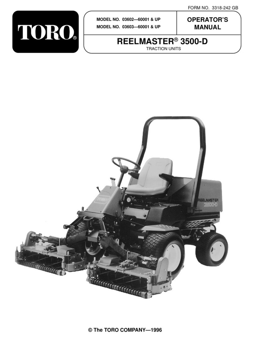
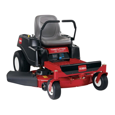
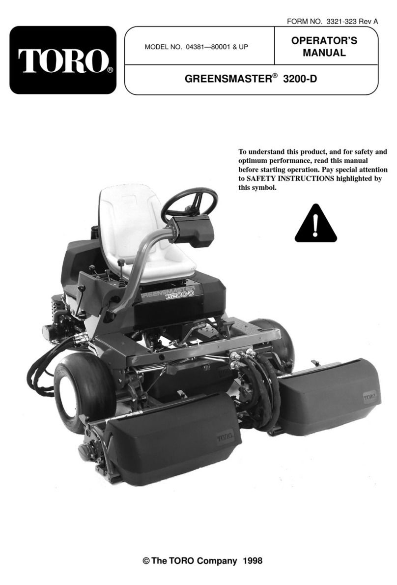
Toro Greensmaster TriFlex 3400 Series User manual

FormNo.3385-938RevB
Greensmaster®3400TriFlex™
TractionUnit
ModelNo.04520—SerialNo.314004001andUp
Registeratwww.Toro.com.
OriginalInstructions(EN)*3385-938*B

ThisproductcomplieswithallrelevantEuropean
directives;fordetails,pleaseseetheseparateproduct
specicDeclarationofConformity(DOC)sheet.
WARNING
CALIFORNIA
Proposition65Warning
Thisproductcontainsachemical
orchemicalsknowntotheStateof
Californiatocausecancer,birthdefects,
orreproductiveharm.
Dieselengineexhaustandsomeofits
constituentsareknowntotheStateof
Californiatocausecancer,birthdefects,
andotherreproductiveharm.
Important:Thisengineisnotequippedwith
asparkarrestermufer.Itisaviolationof
CaliforniaPublicResourceCodeSection4442to
useoroperatetheengineonanyforest-covered,
brush-covered,orgrass-coveredland.Other
statesorfederalareasmayhavesimilarlaws.
Introduction
Thismachineisaride-on,reel-bladelawnmower
intendedtobeusedbyprofessional,hiredoperators
incommercialapplications.Itisprimarilydesignedfor
cuttinggrassonwell-maintainedlawnsinparks,golf
courses,sportselds,andoncommercialgrounds.It
isnotdesignedforcuttingbrush,mowinggrassand
othergrowthalongsidehighways,orforagricultural
uses.
Readthisinformationcarefullytolearnhowtooperate
andmaintainyourproductproperlyandtoavoid
injuryandproductdamage.Youareresponsiblefor
operatingtheproductproperlyandsafely.
YoumaycontactTorodirectlyatwww.T oro.comfor
productandaccessoryinformation,helpndinga
dealer,ortoregisteryourproduct.
Wheneveryouneedservice,genuineT oroparts,or
additionalinformation,contactanAuthorizedService
DealerorT oroCustomerServiceandhavethemodel
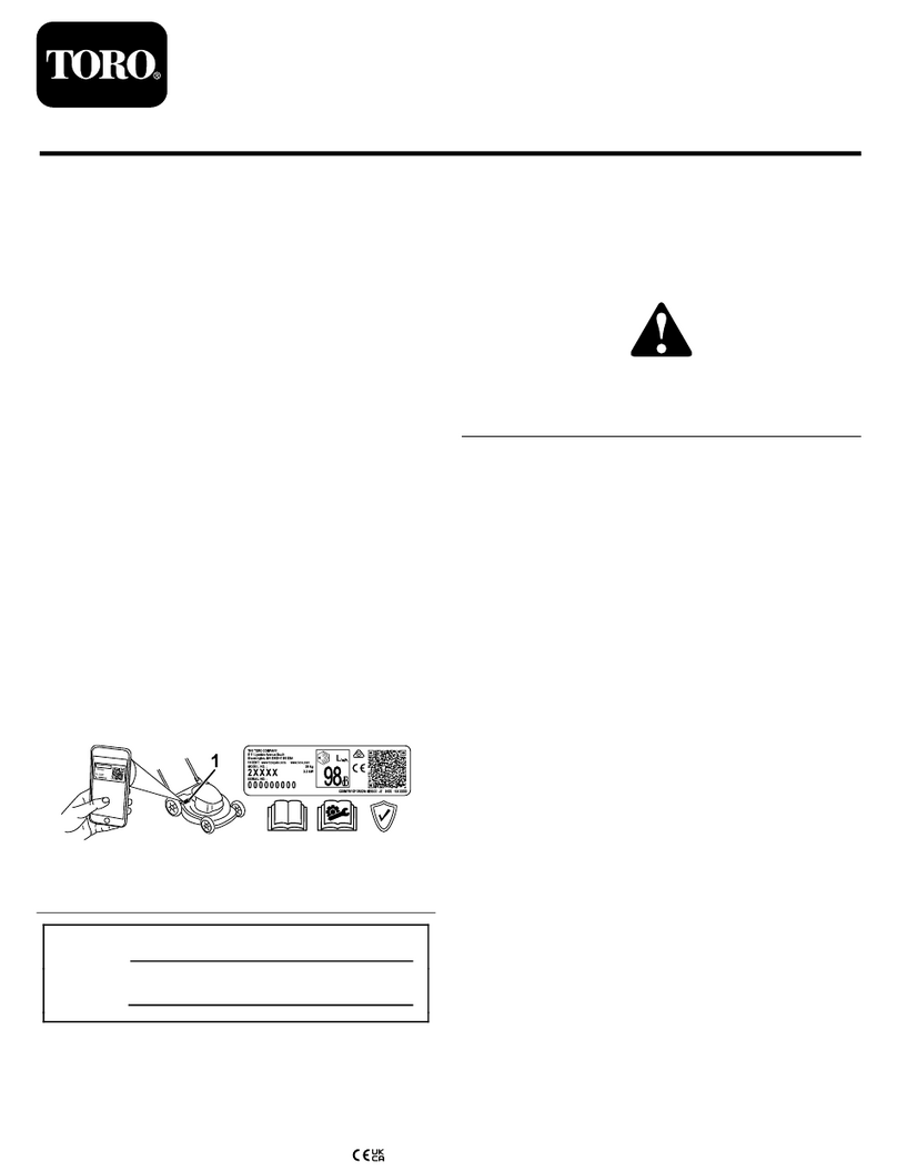
andserialnumbersofyourproductready.Figure1
identiesthelocationofthemodelandserialnumbers
ontheproduct.Writethenumbersinthespace
provided.
g014685
Figure1
1.Modelandserialnumberlocation
ModelNo.
SerialNo.
Thismanualidentiespotentialhazardsandhas
safetymessagesidentiedbythesafetyalertsymbol
(Figure2),whichsignalsahazardthatmaycause
seriousinjuryordeathifyoudonotfollowthe
recommendedprecautions.
g000502
Figure2
1.Safetyalertsymbol
Thismanualuses2wordstohighlightinformation.
Importantcallsattentiontospecialmechanical
informationandNoteemphasizesgeneralinformation
worthyofspecialattention.
©2017—TheToro®Company
8111LyndaleAvenueSouth
Bloomington,MN554202
Contactusatwww.Toro.com.
PrintedintheUSA
AllRightsReserved

Contents
Safety.......................................................................4
SafeOperatingPractices....................................4
ToroMowerSafety..............................................6
SoundPowerLevel............................................8
SoundPressureLevel........................................8
Hand-ArmVibrationLevel..................................8
WholeBodyVibrationLevel...............................8
SafetyandInstructionalDecals..........................8
Setup......................................................................12
1InstallingtheRollBar.....................................13
2InstallingtheSeat..........................................13
3InstallingtheSteeringWheel..........................13
4ActivatingandChargingtheBattery...............14
5InstallingtheOilCooler(optional)...................15
6InstallingtheGrassBasketHooks..................16
7InstallingtheCuttingUnits.............................16
8AddingRearWeight.......................................18
9InstallingtheCEGuardKit.............................18
10InstallingEUDecals.....................................18
ProductOverview...................................................18
Controls...........................................................18
Specications..................................................22
Attachments/Accessories.................................22
Operation................................................................22
ThinkSafetyFirst..............................................22
CheckingtheEngineOil...................................22
FillingtheFuelTank..........................................23
UsingBiodieselFuel.........................................24
CheckingtheCoolingSystem...........................25
CheckingtheHydraulicFluidLevel...................25
DrainingWaterfromtheFuelFilter....................26
CheckingtheTirePressure...............................27
CheckingtheT orqueoftheWheel
Nuts..............................................................27
CheckingtheReel-to-BedknifeContact............27
Breaking-intheMachine...................................27
StartingandStoppingtheMachine...................27
CheckingtheSafetyInterlockSystem...............28
InstallingandRemovingtheCutting
Units..............................................................29
SettingtheReelSpeed.....................................31
MowingwiththeMachine..................................31
TransportingtheMachine.................................32
CleaningandInspectingtheMachine...............32
TowingtheMachine..........................................33
Maintenance...........................................................34
RecommendedMaintenanceSchedule(s)...........34
DailyMaintenanceChecklist.............................35
EngineMaintenance...........................................36
ServicingtheAirCleaner..................................36
ChangingtheEngineOilandFilter....................36
FuelSystemMaintenance...................................37
ServicingtheFuelFilter/Water
Separator......................................................37
InspectingtheFuelLinesand
Connections..................................................38
ElectricalSystemMaintenance...........................38
ServicingtheBattery.........................................38
StoringtheBattery............................................39
LocatingtheFuses...........................................39
DriveSystemMaintenance..................................40
AdjustingtheTransmissionforNeutral..............40
AdjustingtheTransportSpeed..........................40
AdjustingtheMowingSpeed............................40
CoolingSystemMaintenance..............................41
CleaningtheRadiatorScreen...........................41
BrakeMaintenance.............................................42
AdjustingtheBrakes.........................................42
BeltMaintenance................................................42
AdjustingtheAlternatorBelt.............................42
HydraulicSystemMaintenance...........................43
ChangingtheHydraulicOilandFilter................43
CheckingtheHydraulicLinesand
Hoses............................................................43
CuttingUnitMaintenance.....................................44
BacklappingtheReels......................................44
DiagnosticsSystem.............................................45
DiagnosingtheServiceIndicatorLight..............45
Storage...................................................................46
3

Safety
ThismachinemeetsorexceedsCENstandard
EN836:1997,ISOstandard5395:1990,andANSI
B71.4-2012specicationsineffectatthetimeof
productionwhen16.8kg(37lb)ofweightisadded
totherearwheel.
Improperuseormaintenancebytheoperatoror
ownercanresultininjury.Toreducethepotential
forinjury,complywiththesesafetyinstructions
andalwayspayattentiontothesafetyalertsymbol
(Figure2),whichmeansCaution,Warning,or
Danger—personalsafetyinstruction.Failureto
complywiththeinstructionmayresultinpersonal
injuryordeath.
SafeOperatingPractices
ThefollowinginstructionsareadaptedfromCEN
standardEN836:1997,ISOstandard5395:1990,and
ANSIB71.4-2012.
Training
•ReadtheOperator’sManualandothertraining
materialcarefully.Befamiliarwiththecontrols,
safetysigns,andtheproperuseoftheequipment.
•Iftheoperatorormechaniccannotreadthe
languageofthismanual,itistheowner’s
responsibilitytoexplainthismaterialtothem.
•Neverallowchildrenorpeopleunfamiliarwith
theseinstructionstouseorservicethemower.
Localregulationsmayrestricttheageofthe
operator.
•Nevermowwhilepeople,especiallychildren,or
petsarenearby.
•Keepinmindthattheoperatororuseris
responsibleforaccidentsorhazardsoccurringto
otherpeopleortheirproperty.
•Donotcarrypassengers.
•Alldriversandmechanicsshouldseekandobtain
professionalandpracticalinstruction.Theowneris
responsiblefortrainingtheusers.Suchinstruction
shouldemphasize:
–theneedforcareandconcentrationwhen
workingwithride-onmachines;
–controlofaride-onmachineslidingonaslope
willnotberegainedbytheapplicationofthe
brake.Themainreasonsforlossofcontrolare:
◊insufcientwheelgrip;
◊beingdriventoofast;
◊inadequatebraking;
◊thetypeofmachineisunsuitableforthe
task;
◊lackofawarenessoftheeffectofground
conditions,especiallyslopes.
◊Theowner/usercanpreventandis
responsibleforaccidentsorinjuries
occurringtopeople,ordamagetoproperty.
Preparation
•Whilemowing,alwayswearsubstantialfootwear,
longtrousers,hardhat,safetyglasses,and
hearingprotection.Longhair,looseclothing,or
jewelrymaygettangledinmovingparts.Donot
operatetheequipmentwhenbarefootorwearing
opensandals.
•Thoroughlyinspecttheareawheretheequipment
istobeusedandremoveallobjectswhichmaybe
thrownbythemachine.
•Replacefaultysilencers/mufers.
•Evaluatetheterraintodeterminewhataccessories
andattachmentsareneededtoproperlyand
safelyperformthejob.Onlyuseaccessoriesand
attachmentsapprovedbythemanufacturer.
•Checkthatoperator’spresencecontrols,safety
switchesandshieldsareattachedandfunctioning
properly.Donotoperateunlesstheyare
functioningproperly.
Operation
•Donotoperatetheengineinaconnedspace
wheredangerouscarbonmonoxidefumescan
collect.
•Mowonlyindaylightoringoodarticiallight.
•Beforeattemptingtostarttheengine,disengage
allbladeattachmentclutches,shiftintoneutral,
andengagetheparkingbrake.
•Rememberthereisnosuchthingasasafeslope.
Travelongrassslopesrequiresparticularcare.T o
guardagainstoverturning:
–donotstoporstartsuddenlywhengoingup
ordownhill;
–machinespeedsshouldbekeptlowonslopes
andduringtightturns;
–stayalertforhumpsandhollowsandother
hiddenhazards;
–nevermowacrossthefaceoftheslope,unless
themowerisdesignedforthispurpose.
•Stayalertforholesintheterrainandotherhidden
hazards.
•Watchoutfortrafcwhencrossingornear
roadways.
•Stopthebladesfromrotatingbeforecrossing
surfacesotherthangrass.
4

•Whenusinganyattachments,neverdirect
dischargeofmaterialtowardbystandersnorallow
anyonenearthemachinewhileinoperation.
•Neveroperatethemachinewithdamagedguards,
shields,orwithoutsafetyprotectivedevicesin
place.Besureallinterlocksareattached,adjusted
properly,andfunctioningproperly.
•Donotchangetheenginegovernorsettingsor
overspeedtheengine.Operatingtheengineat
excessivespeedmayincreasethehazardof
personalinjury.
•Beforeleavingtheoperator’sposition:
–stoponlevelground;
–disengagethepowertake-offandlowerthe
attachments;
–changeintoneutralandsettheparkingbrake;
–stoptheengineandremovethekey.
•Disengagedrivetoattachmentswhentransporting
ornotinuse.
•Stoptheengineanddisengagedriveto
attachment:
–beforerefuelling;
–beforeremovingthegrasscatcher/catchers;
–beforemakingheightadjustmentunless
adjustmentcanbemadefromtheoperator’s
position.
–beforeclearingblockages;
–beforechecking,cleaningorworkingonthe
mower;
–afterstrikingaforeignobjectorifanabnormal
vibrationoccurs.Inspectthemowerfor
damageandmakerepairsbeforerestarting
andoperatingtheequipment.
•Reducethethrottlesettingbeforestoppingthe
engineand,iftheengineisprovidedwithafuel
shut-offvalve,turnthefueloffattheconclusion
ofmowing.
•Keephandsandfeetawayfromthecuttingunits.
•Lookbehindanddownbeforebackinguptobe
sureofaclearpath.
•Slowdownandusecautionwhenmakingturns
andcrossingroadsandsidewalks.Stopthereels
whennotmowing.
•Donotoperatethemowerundertheinuenceof
alcoholordrugs.
•Lightningcancausesevereinjuryordeath.If
lightningisseenorthunderisheardinthearea,do
notoperatethemachine;seekshelter.
•Usecarewhenloadingorunloadingthemachine
intoatrailerortruck.
•Usecarewhenapproachingblindcorners,shrubs,
trees,orotherobjectsthatmayobscurevision.
RolloverProtectionSystem
(ROPS)-UseandMaintenance
•TheROPSisanintegralandeffectivesafety
device.KeepafoldingROPSintheraised
andlockedpositionandusetheseatbeltwhen
operatingthemachine.
•LowerafoldingROPStemporarilyonlywhen
absolutelynecessary.Donotweartheseatbelt
whenfoldeddown.
•Beawarethereisnorolloverprotectionwhena
foldedROPSisinthedownposition.
•Becertainthattheseatbeltcanbereleased
quicklyintheeventofanemergency.
•Checktheareatobemowedandneverfolddown
afoldingROPSinareaswherethereareslopes,
dropoffsorwater.
•Checkcarefullyforoverheadclearances(i.e.
branches,doorways,electricalwires)before
drivingunderanyobjectsanddonotcontactthem.
•KeeptheROPSinsafeoperatingconditionby
periodicallythoroughlyinspectingfordamageand
keepingallmountingfastenerstight.
•ReplaceadamagedROPS.Donotrepairor
revise.
•DonotremovetheROPS.
•AnyalterationstoaROPSmustbeapprovedby
themanufacturer.
SafeHandlingofFuels
•Toavoidpersonalinjuryorpropertydamage,use
extremecareinhandlinggasoline.Gasolineis
extremelyammableandthevaporsareexplosive.
•Extinguishallcigarettes,cigars,pipes,andother
sourcesofignition.
•Useonlyanapprovedfuelcontainer.
•Neverremovefuelcaporaddfuelwiththeengine
running.
•Allowenginetocoolbeforerefueling.
•Neverrefuelthemachineindoors.
•Neverstorethemachineorfuelcontainerwhere
thereisanopename,spark,orpilotlightsuchas
onawaterheateroronotherappliances.
•Neverllcontainersinsideavehicleoronatruck
ortrailerbedwithaplasticliner.Alwaysplace
containersonthegroundawayfromyourvehicle
beforelling.
•Removeequipmentfromthetruckortrailerand
refuelitontheground.Ifthisisnotpossible,then
refuelsuchequipmentwithaportablecontainer,
ratherthanfromafueldispensernozzle.
5

•Keepthenozzleincontactwiththerimofthefuel
tankorcontaineropeningatalltimesuntilfueling
iscomplete.
•Donotuseanozzlelockopendevice.
•Iffuelisspilledonclothing,changeclothing
immediately.
•Neveroverllfueltank.Replacefuelcapand
tightensecurely.
MaintenanceandStorage
•Keepallnuts,boltsandscrewstighttobesurethe
equipmentisinsafeworkingcondition.
•Neverstoretheequipmentwithfuelinthetank
insideabuildingwherefumesmayreachanopen
ameorspark.
•Allowtheenginetocoolbeforestoringinany
enclosure.
•Toreducetheriskofrehazard,keeptheengine,
silencer/mufer,batterycompartment,andfuel
storageareafreeofgrass,leaves,orexcessive
grease.
•Replacewornordamagedpartsforsafety.
•Checkthegrasscatcherfrequentlyforwearor
deterioration.
•Keepallpartsingoodworkingconditionandall
hardwareandhydraulicttingstightened.Replace
allwornordamagedpartsanddecals.
•Ifthefueltankhastobedrained,dothisoutdoors.
•Becarefulduringadjustmentofthemachineto
prevententrapmentofthengersbetweenmoving
bladesandxedpartsofthemachine.
•Onmulti-reelmachines,takecareasrotatingone
reelcancauseotherreelstorotate.
•Disengagedrives,lowerthecuttingunits,set
parkingbrake,stopengineandremovekey.Wait
forallmovementtostopbeforeadjusting,cleaning
orrepairing.
•Cleangrassanddebrisfromcuttingunits,drives,
mufers,andenginetohelppreventres.Clean
upoilorfuelspillage.
•Usejackstandstosupportcomponentswhen
required.
•Carefullyreleasepressurefromcomponentswith
storedenergy.
•Disconnectbatterybeforemakinganyrepairs.
Disconnectthenegativeterminalrstandthe
positivelast.Reconnectpositiverstandnegative
last.
•Usecarewhencheckingthereels.Wrapthereels
orweargloves,andusecautionwhenservicing
them.
•Keephandsandfeetawayfrommovingparts.If
possible,donotmakeadjustmentswiththeengine
running.
•Chargebatteriesinanopenwellventilatedarea,
awayfromsparkandames.Unplugcharger
beforeconnectingordisconnectingfrombattery.
Wearprotectiveclothinganduseinsulatedtools.
Hauling
•Usecarewhenloadingorunloadingthemachine
intoatrailerortruck.
•Usefullwidthrampsforloadingmachineinto
trailerortruck.
•Tiethemachinedownsecurelyusingstraps,
chains,cable,orropes.Bothfrontandrearstraps
shouldbedirecteddownandoutwardfromthe
machine.
ToroMowerSafety
Thefollowinglistcontainssafetyinformationspecic
toToroproductsorothersafetyinformationthatyou
mustknowthatisnotincludedintheANSIstandards.
Thisproductiscapableofamputatinghandsand
feetandthrowingobjects.Alwaysfollowallsafety
instructionstoavoidseriousinjuryordeath.
Useofthisproductforpurposesotherthanitsintended
usecouldprovedangeroustouserandbystanders.
Operation
•Knowhowtostoptheenginequickly.
•Alwayswearsubstantialshoes.Donotoperatethe
machinewhilewearingsandals,tennisshoes,or
sneakers.Wearingsafetyshoesandlongpantsis
advisableandrequiredbysomelocalordinances
andinsuranceregulations.
•Theoperatormustbeskilledandtrainedinhowto
driveonhillsides.Failuretousecautiononslopes
orhillsmaycauselossofcontrolandcausethe
vehicletotiporroll,possiblyresultinginpersonal
injuryordeath.
•Handlefuelcarefully.Wipeupanyspills.
•Checkthesafetyinterlockswitchesdailyforproper
operation.Ifaswitchshouldfail,replacethe
switchbeforeoperatingthemachine
•Beforeattemptingtostarttheengine,sitonthe
seat,pulltheliftleverbackandreleaseittoensure
thecuttingunitsaredisengaged.Verifythatthe
tractionsystemisinneutralandtheparkingbrake
isset.
•Usingthemachinedemandsattention.T oprevent
lossofcontrol:
6

–Donotdriveclosetosandtraps,ditches,
creeks,orotherhazards.
–Reducespeedwhenmakingsharpturns.
Avoidsuddenstopsandstarts.
–Watchoutfortrafcwhennearorcrossing
roads.Alwaysyieldtheright-of-way.
–Applytheservicebrakeswhengoingdownhill
tokeepforwardspeedslowandtomaintain
controlofthemachine.
•Thegrassbasketsmustbeinplaceduring
operationofthereelsorthatchersformaximum
safety.Shuttheengineoffbeforeemptyingthe
baskets.
•Raisethecuttingunitswhendrivingfromonework
areatoanother.
•Donottouchtheengine,mufer,orexhaustpipe
whiletheengineisrunningorsoonafterithas
stoppedbecausetheseareascouldbehotenough
tocauseburns.
•Beforegettingoffoftheseat,movethefunctional
controllevertoneutral(N),raisethecuttingunits
andwaitforthereelstostopspinning.Setthe
parkingbrake.Stoptheengineandremovethe
keyfromtheignitionswitch.
•Traverseslopescarefully.Donotstartorstop
suddenlywhentravelinguphillordownhill.
•Theoperatormustbeskilledandtrainedinhowto
driveonhillsides.Failuretousecautiononslopes
orhillsmaycauselossofcontrolandcausethe
machinetotiporroll,possiblyresultinginpersonal
injuryordeath.
•Iftheenginestallsorlosesheadwayandcannot
makeittothetopofaslope,donotturnthe
machinearound.Alwaysbackslowly,straight
downtheslope.
•Whenapersonorpetappearsunexpectedlyinor
nearthemowingarea,stopmowing.Careless
operation,combinedwithterrainangles,ricochets,
orimproperlypositionedguardscanleadtothrown
objectinjuries.Donotresumemowinguntilthe
areaiscleared.
•AlwaysusetheseatbeltwiththeROPSwhen
operatingthemachine.
•Beforegettingoffoftheseat,movethefunctional
controllevertoneutral(N),raisethecuttingunits
andwaitforthereelstostopspinning.Setthe
parkingbrake.Stoptheengineandremovethe
keyfromtheignitionswitch.
•Wheneverthemachineisleftunattended,make
surethecuttingunitsarefullyraised,thereelsare
notspinning,thekeyisremovedfromtheignition
switch,andtheparkingbrakeisset.
MaintenanceandStorage
•Makesureallhydrauliclineconnectorsaretight
andallhydraulichosesandlinesareingood
conditionbeforeapplyingpressuretothesystem.
•Keepyourbodyandhandsawayfrompinhole
leaksornozzlesthatejecthydraulicuidunder
highpressure.Usepaperorcardboard,not
yourhands,tosearchforleaks.Hydraulicuid
escapingunderpressurecanhavesufcientforce
topenetratetheskinandcauseseriousinjury.
•Beforedisconnectingorperforminganyworkon
thehydraulicsystem,allpressureinthesystem
mustberelievedbystoppingtheengineand
loweringthecuttingunitsandattachmentstothe
ground.
•Checkallfuellinesfortightnessandwearona
regularbasis.Tightenorrepairthemasneeded.
•Iftheenginemustberunningtoperforma
maintenanceadjustment,keephands,feet,
clothing,andanypartsofthebodyawayfromthe
cuttingunits,attachments,andanymovingparts,
especiallythescreenatthesideoftheengine.
Keepeveryoneaway.
•Toensuresafetyandaccuracy,haveanAuthorized
ToroDistributorcheckthemaximumenginespeed
withatachometer.Maximumgovernedengine
speedshouldbe2900rpm.
•Theenginemustbeshutoffbeforecheckingthe
oiloraddingoiltothecrankcase.
•Ifmajorrepairsareeverneededorifassistanceis
desired,contactanAuthorizedT oroDistributor.
•Toensureoptimumperformanceandcontinued
safetycerticationofthemachine,useonly
genuineTororeplacementpartsandaccessories.
Replacementpartsandaccessoriesmadeby
othermanufacturerscouldbedangerous,and
suchusecouldvoidtheproductwarranty.
7

SoundPowerLevel
Thisunithasaguaranteedsoundpowerlevelof98
dBA,whichincludesanUncertaintyValue(K)of1
dBA.
Soundpowerlevelwasdeterminedaccordingtothe
proceduresoutlinedinISO11094.
SoundPressureLevel
Thisunithasasoundpressurelevelattheoperator’s
earof84dBA,whichincludesanUncertaintyValue
(K)of1dBA.
Soundpressurelevelwasdeterminedaccordingto
theproceduresoutlinedinEN836.
Hand-ArmVibrationLevel
Measuredvibrationlevelforrighthand=0.22m/s2
Measuredvibrationlevelforlefthand=0.24m/s2
UncertaintyValue(K)=0.24m/s2
Measuredvaluesweredeterminedaccordingtothe
proceduresoutlinedinEN836.
WholeBodyVibrationLevel
Measuredvibrationlevel=0.41m/s2
UncertaintyValue(K)=0.21m/s2
Measuredvaluesweredeterminedaccordingtothe
proceduresoutlinedinEN836.
SafetyandInstructionalDecals
Safetydecalsandinstructionsareeasilyvisibletotheoperatorandarelocatednearanyarea
ofpotentialdanger.Replaceanydecalthatisdamagedorlost.
decal119-9343
119-9343
8

decal115-8156
115-8156
1.Reelheight3.8Bladecuttingunit5.14Bladecuttingunit7.Fast
2.5Bladecuttingunit4.11Bladecuttingunit6.Reelspeed8.Slow
decal115-8155
115-8155
1.Warning—readtheOperator'sManual,donotprimeoruse
startinguid.
decal115-8203
115-8203
1.ReadtheOperator's
manualforfuse
information.
2.Radiatorfan—50Amp
decal117-2718
117–2718
decal121-5169
121–5169
1.Slow5.Reelposition
setting
9.Slow—usefor
mowing
2.Continuous
variablesetting
6.Lowerand
engagethe
reels
10.Fast—usefor
transport
3.Fast7.Reel—backlapping 11.Functional
controllever
4.Raisethereels8.Neutral—use
forbacklapping
9

decal121-5172
121–5172
1.Off3.On
2.Headlights
decal121-5170
121–5170
1.Hydraulicoillevel4.Engine—start
2.ReadtheOperator’s
Manualbeforeservicingor
performingmaintenance.
5.Enginepreheat/run
3.Choke(gasolinemodels
only)
6.Engine—stop
decal119-9346
119-9346
1.Presspedaltounlock2.ReadtheOperator's
Manualformore
information.
decalbatterysymbols
BatterySymbols
Someorallofthesesymbolsareonyourbattery.
1.Explosionhazard6.Keepbystandersasafe
distancefromthebattery.
2.Nore,openames,or
smoking.
7.Weareyeprotection;
explosivegasescan
causeblindnessandother
injuries.
3.Causticliquid/chemical
burnhazard
8.Batteryacidcancause
blindnessorsevereburns.
4.Weareyeprotection.9.Flusheyesimmediately
withwaterandgetmedical
helpfast.
5.ReadtheOperator’s
Manual.
10.Containslead;donot
discard.
decal121-2641
121–2641
1.Warning—readthe
Operator’sManual,do
notoperatethismachine
unlessyouaretrained.
4.Tippinghazard—slow
machinebeforeturning,
donotturnathighspeeds.
2.Thrownobject
hazard—keepbystanders
asafedistancefromthe
machine.
5.Warning—locktheparking
brake,stoptheengine
andremovetheignition
keybeforeleavingthe
machine.
3.Cutting/dismemberment
hazardofhandorfoot,
mowerblade—stayaway
frommovingparts;keep
allguardsandshieldsin
place.
10

decal121-2640
121–2640
1.Warning—readthe
Operator’sManual,do
notoperatethismachine
unlessyouaretrained.
4.Tippinghazard—donot
driveacrossslopesgreater
than15degreesordown
slopesgreaterthan15
degrees.
2.Thrownobject
hazard—keepbystanders
asafedistancefromthe
machine
5.Warning—locktheparking
brake,stoptheengine
andremovetheignition
keybeforeleavingthe
machine.
3.Cutting/dismemberment
hazardofhandorfoot,
mowerblade—stayaway
frommovingparts;keep
allguardsandshieldsin
place.
11

Setup
LooseParts
Usethechartbelowtoverifythatallpartshavebeenshipped.
ProcedureDescriptionQty.Use
Rollbar1
Bolt(1/2x3-3/4inches)4
1Flange-nut(1/2inch)4
Installtherollbar.
2Seatcompletionkit1Installtheseattothebase.
Steeringwheel1
Locknut(1-1/2inches)1
Washer1
3Steeringwheelcap1
Installthesteeringwheel.
4Nopartsrequired–Activateandchargethebattery.
5Nopartsrequired–Installtheoilcooler(optional).
Grassbaskethook6
6Flangebolts12Installthegrassbaskethooks.
Gaugebar1
Cuttingunit(model04613,04614,or
04615)3
7GrassBasket3
Installthecuttingunits.
8
Weightkit,121–6665(purchase
separately)Note:Thiskitisnotrequired
forunitswiththe3wheeldrivekit
installed.
1Addrearweight.
9CEGuardKit―PartNo.04442(sold
separately)1InstalltheCEguardkit.
10Warningdecal117-95371InstallEUdecals,ifrequired.
MediaandAdditionalParts
DescriptionQty.Use
Operator'sManual(machine)1
EngineOperator'sManual(engine)1Readbeforeoperatingthemachine.
PartsCatalog1Saveforfuturepartsordering.
OperatorTrainingMaterials1Viewbeforeoperatingthemachine.
Pre-deliveryInspectionSheet1
Noiseratingcerticate1
Certicateofcompliance1
Saveforfuturereference.
Ignitionkeys2Starttheengine.
12

1
InstallingtheRollBar
Partsneededforthisprocedure:
1Rollbar
4Bolt(1/2x3-3/4inches)
4Flange-nut(1/2inch)
Procedure
1.Removethetopcratesupportfromthecrate.
2.Removetherollbarfromthecrate.
3.Installtherollbarintothepocketsoneachside
ofthemachine,using4bolts(1/2x3-3/4inches)
and4ange-nuts(1/2inch)(Figure3).
g014601
Figure3
1.Rollbar3.Flange-nut(1/2inch)
2.Bolt(1/2x3-3/4inches)
4.Torquethefastenersto136to149N-m(100to
110ft-lb).
2
InstallingtheSeat
Partsneededforthisprocedure:
1Seatcompletionkit
Procedure
Acquireyourdesiredseatkitfromyourdistributorand
installitasdirectedintheinstructionincludedwith
thekit.
3
InstallingtheSteering
Wheel
Partsneededforthisprocedure:
1Steeringwheel
1Locknut(1-1/2inches)
1Washer
1Steeringwheelcap
Procedure
1.Slidethesteeringwheelontothesteeringshaft
(Figure4).
g010834
Figure4
1.Steeringwheel3.Jamnut
2.Washer4.Cap
2.Slidethewasherontothesteeringshaft(Figure
4).
13

3.Securethesteeringwheeltotheshaftwitha
jamnutandtightenitto27to35N-m(20to26
ft-lb)(Figure4).
4.Installthecaptothesteeringwheelandsecure
itwithascrew(Figure4).
4
ActivatingandCharging
theBattery
NoPartsRequired
Procedure
Useonlyelectrolyte(1.265specicgravity)tollthe
batteryinitially.
1.Removethefastenersandbatteryclampand
liftoutthebattery.
Important:Donotaddelectrolytewhilethe
batteryisinthemachine.Youcouldspillit,
causingcorrosion.
2.Cleanthetopofthebatteryandremovethevent
caps(Figure5).
g005080
Figure5
3.Carefullylleachcellwithelectrolyteuntilthe
platesarecoveredwithabout6mm(1/4inch)
ofuid(Figure6).
g001197
Figure6
1.Electrolyte
4.Allowapproximately20to30minutesforthe
electrolytetosoakintotheplates.Fillas
necessarytobringtheelectrolytetowithinabout
6mm(1/4inch)ofthebottomofthellwell
(Figure6).
WARNING
Chargingthebatteryproducesgasses
thatcanexplode.
Neversmokenearthebatteryandkeep
sparksandamesawayfrombattery.
5.Connecta2to4ampbatterychargertothe
batteryposts.Chargethebatteryfor2hoursat
4ampsorfor4hoursat2ampsuntilthespecic
gravityis1.250orhigherandthetemperatureis
atleast16°C(60°F)withallcellsgassingfreely.
6.Whenthebatteryischarged,disconnectthe
chargerfromtheelectricaloutletandbattery
posts.
Note:Afterthebatteryhasbeenactivated,
addonlydistilledwatertoreplacenormalloss,
althoughmaintenance-freebatteriesshouldnot
requirewaterundernormaloperatingconditions.
WARNING
CALIFORNIA
Proposition65Warning
Batteryposts,terminals,andrelated
accessoriescontainleadandlead
compounds,chemicalsknownto
theStateofCaliforniatocause
cancerandreproductiveharm.Wash
handsafterhandling.
14

WARNING
Batteryterminalsormetaltoolscould
shortagainstmetaltractorcomponents
causingsparks.Sparkscancausethe
batterygassestoexplode,resultingin
personalinjury.
•Whenremovingorinstallingthe
battery,donotallowthebattery
terminalstotouchanymetalpartsof
thetractor.
•Donotallowmetaltoolstoshort
betweenthebatteryterminalsand
metalpartsofthetractor.
WARNING
Failuretocorrectlyactivatethebattery
mayresultinbatterygassingand/or
prematurebatteryfailure.
7.Placethebatteryonthebatterytrayandsecure
itwiththebatteryclampandfasternersremoved
previously.
8.Installthepositivecable(red)tothepositive(+)
terminalandthenthenegativecable(black)
tothenegative(–)terminalofthebatteryand
securethemwiththeboltsandnuts(Figure7).
Slidetherubberbootoverthepositiveterminal
topreventapossibleshortfromoccurring.
WARNING
Incorrectbatterycableroutingcoulddamage
thetractorandcablescausingsparks.Sparks
cancausethebatterygassestoexplode,
resultinginpersonalinjury.
•Alwaysdisconnectthenegative(black)
batterycablebeforedisconnectingthe
positive(red)cable.
•Alwaysconnectthepositive(red)battery
cablebeforeconnectingthenegative
(black)cable.
g005098
Figure7
1.Negative(-)
2.Positive(+)
5
InstallingtheOilCooler
(optional)
NoPartsRequired
Procedure
Ifyouareoperatingthemachineinhotclimates,
whereambienttemperaturesareabove29°C(85°
F),orusingitforheavy-dutyuse(mowingotherthan
greens,suchasfairwaysorverticutting),installa
HydraulicOilCoolerKit,PartNo.117-9314,tothe
machine.
15

6
InstallingtheGrassBasket
Hooks
Partsneededforthisprocedure:
6Grassbaskethook
12Flangebolts
Procedure
Installthe6grassbaskethooksontotheendsofthe
suspensionarmbarsusing12angebolts(Figure8).
g015492
Figure8
1.Flangebolt3.Suspensionarmbar
2.Grassbaskethook
7
InstallingtheCuttingUnits
Partsneededforthisprocedure:
1Gaugebar
3Cuttingunit(model04613,04614,or04615)
3GrassBasket
Procedure
Note:Whensharpening,settingtheheight-of-cut,
orperformingothermaintenanceproceduresonthe
cuttingunits,storethecuttingunitreelmotorsinthe
storagelocationonthefrontofthesuspensionarms
topreventdamagetothem.
Important:Donotraisethesuspensiontothe
transportpositionwhenthereelmotorsarein
theholdersinthemachineframe.Damagetothe
motorsorhosescouldresult.
Important:Wheneverthecuttingunithastobe
tippedtoexposebedknife/reel,propuprearof
cuttingunittomakesurenutsonbackendof
bedbaradjustingscrewsarenotrestingonwork
surface(Figure9).
g014596
Figure9
1.Prop(notprovided)2.Bedknifeadjustingscrew
nut(2)
Note:Allcuttingunitsareshippedwiththecounter
weightmountedtotherightendandthemotormount
anddrivecouplermountedtotheleftendofthe
cuttingunit.
1.Applygreasetotheinsidediameterofthedrive
coupler.
2.Thecuttingunitisshippedwithoutafrontroller.
Obtainaroller(ModelNo.04625,04626or
04627)fromyourlocalT oroDistributor.Install
therollerusingtheloosepartssuppliedwiththe
cuttingunitandinstallationinstructionsincluded
withtheroller.
3.Ifinstallingthecentercuttingunit,liftuponthe
footrestandswingitup,allowingaccesstothe
centercuttingunitposition(Figure10).
CAUTION
Thefootrestcanpinchngersifitfalls
intotheclosedposition.
Keepyourngersclearoftheareawhere
thefootrestseatswhileitisopen.
16

g014602
Figure10
1.Footrest—closed2.Footrest—open
4.Positionthecuttingunitunderthesuspension
arm.
5.Withthelatchesonthesuspension-armbar
pointingup(i.e.,open)(Figure11),pushthe
suspensionarmdownsothatthebartsover
thebaracrossthetopofthecuttingunit(Figure
12).
g014609
Figure11
1.Latch—closedposition3.Latch—openposition
2.Suspension-armbar
g014611
Figure12
1.Suspension-armbar2.Cutting-unitbar
6.Closethelatchesdownandaroundthe
cutting-unitbarandlocktheminplace(Figure
11).
Note:A“click”canbeheardandfeltwhenthe
latchesareproperlylockedinplace.
7.Coatthesplineshaftofthecuttingunitmotor
withcleangrease(Figure13).
8.Insertthemotorintotheleftsideofthecutting
unit(asviewedfromtheoperator'sposition)and
pullthemotorretainingbaronthecuttingunit
towardthemotoruntilyouhearanaudible“click”
frombothsidesofthemotor(Figure13).
g014690
Figure13
1.Reelmotor3.Cavity
2.Splineshaft4.Motorretainingbar
9.Mountagrassbasketontothebaskethookson
thesuspensionarm.
10.Repeatthisprocedurefortheothercuttingunits.
17

8
AddingRearWeight
Partsneededforthisprocedure:
1
Weightkit,121–6665(purchaseseparately)Note:
Thiskitisnotrequiredforunitswiththe3wheeldrive
kitinstalled.
Procedure
ThisunitcomplieswiththeANSIB71.4-2004and
EN836Standardswhenequippedwithweightkit
121–6665.
Note:Iftheunitisequippedwithathreewheeldrive
kitadditionalweightisnotrequiredtomeetANSI
B71.4-2004andEN836standards.
9
InstallingtheCEGuardKit
Partsneededforthisprocedure:
1CEGuardKit―PartNo.04442(soldseparately)
Procedure
InstalltheCEguardkit;refertotheCEGuardKitfor
Greensmaster3400TriFlexTractionUnitInstallation
instructions.
10
InstallingEUDecals
Partsneededforthisprocedure:
1Warningdecal117-9537
Procedure
IfthismachinewillbeusedintheEU,afxthewarning
decal117-9537overEnglishwarningdecal117-9536.
ProductOverview
g014674
Figure14
1.Engine5.Steeringwheel
2.Rollbar6.Tractionpedal
3.Controlpanel7.Footrest
4.Seat8.Reelswithgrassbaskets
Controls
TractionPedal
Thetractionpedal(Figure15)hasthreefunctions:
tomakethemachinemoveforward,tomoveit
backward,andtostopthemachine.Pressthetop
ofthepedaltomoveforwardandthebottomofthe
pedaltomovebackwardortoassistinstoppingwhen
movingforward.Also,allowthepedaltomovetothe
neutralpositiontostopthemachine.Foroperator
comfort,donotresttheheelofyourfootonreverse
whenoperatingforward(Figure16).
18

g014603
Figure15
1.Tractionpedal—forward3.Steeringarmlockingpedal
2.Tactionpedal—reverse
g005105
Figure16
SteeringArmLockingPedal
Pressthepedal(Figure15)andraiseorlowerthe
steeringarmforoperatorcomfort,then,releasethe
pedaltolockthearminplace.
ThrottleControl
Thethrottlecontrol(Figure17)givestheoperatorthe
abilitytocontrolthespeedoftheengine.Movingthe
throttlecontroltowardtheFastpositionincreasesthe
enginerpm;movingthethrottlecontroltowardSlow
willdecreasetheenginerpm.Groundspeedsare
asfollows:
•3.2to8km/h(2to5mph)forwardmowingspeed
•16km/h(10mph)maximumtransportspeed
•4.0km/h(2.5mph)reversespeed
Note:Theenginecannotbestoppedbytheuseof
thethrottlecontrol.
g014599
Figure17
1.Throttlecontrol6.Batterywarninglight
2.Raise/LowerMowControl7.Serviceindicatorlight
3.Functionalcontrollever8.Glowplugindicatorlight
4.Ignitionswitch9.Watertemperaturelight
5.Engineoilpressurelight
Raise/LowerMowControl
Movingthecontrol(Figure17)forwardduring
operationlowersthecuttingunitsandstartsthereels.
Pullbackonthecontroltostopthereelsandraise
thecuttingunits.Duringoperationthereelscanbe
stoppedbypullingbackonthecontrolmomentarily
andreleasingit.Startthereelsbymovingthecontrol
forward.
FunctionalControlLever
Thefunctionalcontrollever(Figure17)provides
twotractionselectionsplusaNeutralposition.Itis
permissibletoshiftfrommowtotransportortransport
tomow(nottoneutral)whilethemachineisinmotion.
Nodamagewillresult.
•RearPosition—neutralandbacklapping
•MiddlePosition—usedformowingoperation
•FrontPosition—usedfortransportoperation
IgnitionSwitch
Insertthekeyintotheswitch(Figure17)andturnit
clockwiseasfaraspossibletotheStartpositionto
starttheengine.Releasethekeyassoonasthe
enginestarts;thekeywillmovetotheOnposition.
TurnthekeycounterclockwisetotheOffpositionto
stoptheengine.
19

BatteryWarningLight
Thelight(Figure17)glowsifthebatterychargeislow.
EngineOilPressureLight
Thelight(Figure17)glowsiftheengineoilpressure
dropsbelowasafelevel.
WaterTemperatureLight
Thelight(Figure17)glowsandtheengine
automaticallyshutsdownwhentheenginecoolant
temperaturegetstoohigh.Iftheengineshutsdown,
youcanstarttheengineanddrivethemachinefor10
secondsbeforeitwillshutdownagain,allowingyouto
movethemachinetoalocationwhereyoucanallow
ittocooldown.
ServiceIndicatorLight
Theserviceindicatorlight(Figure17)illuminates
whenthemachinesensorsdetectanissuewithone
ofthesystemsofthemachine.Ifthislightilluminates,
stopwhatyouaredoinganddrivetoasafelocation
whereyouoraservicetechniciancandiagnose
theproblem.Formoreinformationondiagnosing
systemissuesusingtheserviceindicatorlight,referto
DiagnosingtheServiceIndicatorLight(page45).
GlowPlugIndicatorLight
Whentheglowplugindicatorlight(Figure17)islit,it
indicatestheglowplugsareon.
Note:Theglowplugindicatorlightmayilluminate
forashorttimeaftertheenginehasstarted;thisis
normal.
HourMeter
Thehourmeter(Figure18)indicatesthetotalhours
themachinehasoperated.Itstartstofunction
wheneverthekeyswitchisrotatedtoOn.
g014600
Figure18
1.Hourmeter
ParkingBrakeLever
Pulluponthebrakelever(Figure15)tosetthe
parkingbrake.Disengageitbypushingitforwardand
down.Locktheparkingbrakeanytimeyouleavethe
machine.
g014610
Figure19
BacklapLever
Thebacklapleverislocatedundertheplasticcoverto
theleftoftheseat.Usethebacklaplever(Figure20)
inconjunctionwiththeraise/lowermowcontrollever
andthereelspeedcontrolforbacklappingthereels.
20
Table of contents
Other Toro Lawn Mower manuals

Toro
Toro 20955 User manual

Toro
Toro 21611 User manual

Toro
Toro 22289 User manual

Toro
Toro 30849 User manual

Toro
Toro 14AP80RP544 User manual

Toro
Toro 74209 User manual

Toro
Toro TimeCutter MX50 79024 User manual

Toro
Toro 04054 Greensmaster 800 User manual

Toro
Toro 74504TE User manual

Toro
Toro eHoverPro 450 User manual
Popular Lawn Mower manuals by other brands

Brill
Brill Hattrick 36 EH manual

EINHELL
EINHELL GP-CM 36/47 S HW Li Original operating instructions

Jacobsen
Jacobsen 69168 - Turfcat T628D Safety & operation manual

McCulloch
McCulloch M51-120M CLASSIC Operator's manual

Scheppach
Scheppach MR760-E Translation of original instruction manual

Husqvarna
Husqvarna TC 142T instruction manual