Toro GreensPro 1260 Greens Roller User manual

FormNo.3423-912RevB
GreensPro™1260GreensRoller
ModelNo.44913—SerialNo.403316784andUp
Registeratwww.Toro.com.
OriginalInstructions(EN)*3423-912*B

ThisproductcomplieswithallrelevantEuropean
directives.Fordetails,pleaseseetheseparate
productspecicDeclarationofConformity(DOC)
sheet.
ItisaviolationofCaliforniaPublicResourceCode
Section4442or4443touseoroperatetheengineon
anyforest-covered,brush-covered,orgrass-covered
landunlesstheengineisequippedwithaspark
arrester,asdenedinSection4442,maintainedin
effectiveworkingorderortheengineisconstructed,
equipped,andmaintainedforthepreventionofre.
WARNING
CALIFORNIA
Proposition65Warning
Theengineexhaustfromthisproduct
containschemicalsknowntotheStateof
Californiatocausecancer,birthdefects,
orotherreproductiveharm.
Useofthisproductmaycauseexposure
tochemicalsknowntotheStateof
Californiatocausecancer,birthdefects,
orotherreproductiveharm.
Introduction
Thismachineisaride-ongreensrollerintendedtobe
usedbyprofessional,hiredoperatorsincommercial
applications.Itisprimarilydesignedforrolling
greens,tenniscourts,andotherneturfsurfaceson
well-maintainedlawnsinparks,golfcourses,sports
elds,andoncommercialgrounds.
Readthisinformationcarefullytolearnhowtooperate
andmaintainyourproductproperlyandtoavoid
injuryandproductdamage.Youareresponsiblefor
operatingtheproductproperlyandsafely.
Visitwww.T oro.comformoreinformation,including
safetytips,trainingmaterials,accessoryinformation,
helpndingadealer,ortoregisteryourproduct.
Wheneveryouneedservice,genuineToroparts,or
additionalinformation,contactanAuthorizedService
DealerorT oroCustomerServiceandhavethemodel
andserialnumbersofyourproductready.Figure1
identiesthelocationofthemodelandserialnumbers
ontheproduct.Writethenumbersinthespace
provided.
g036786
Figure1
1.Locationofthemodelandserialnumbers
ModelNo.
SerialNo.
Thismanualidentiespotentialhazardsandhas
safetymessagesidentiedbythesafety-alertsymbol
(Figure2),whichsignalsahazardthatmaycause
seriousinjuryordeathifyoudonotfollowthe
recommendedprecautions.
g000502
Figure2
Safety-alertsymbol
Thismanualuses2wordstohighlightinformation.
Importantcallsattentiontospecialmechanical
informationandNoteemphasizesgeneralinformation
worthyofspecialattention.
©2018—TheToro®Company
8111LyndaleAvenueSouth
Bloomington,MN554202
Contactusatwww.Toro.com.
PrintedintheUK
AllRightsReserved

Contents
Safety.......................................................................4
GeneralSafety...................................................4
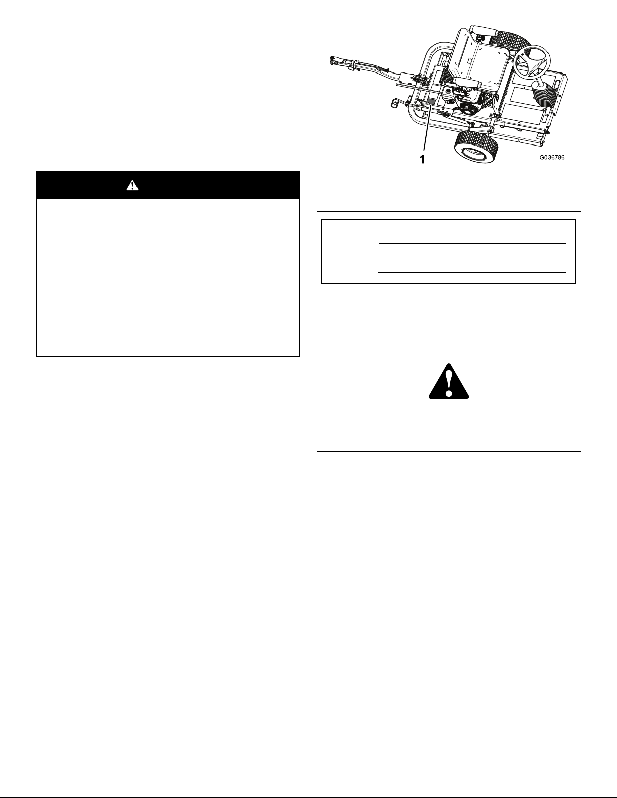
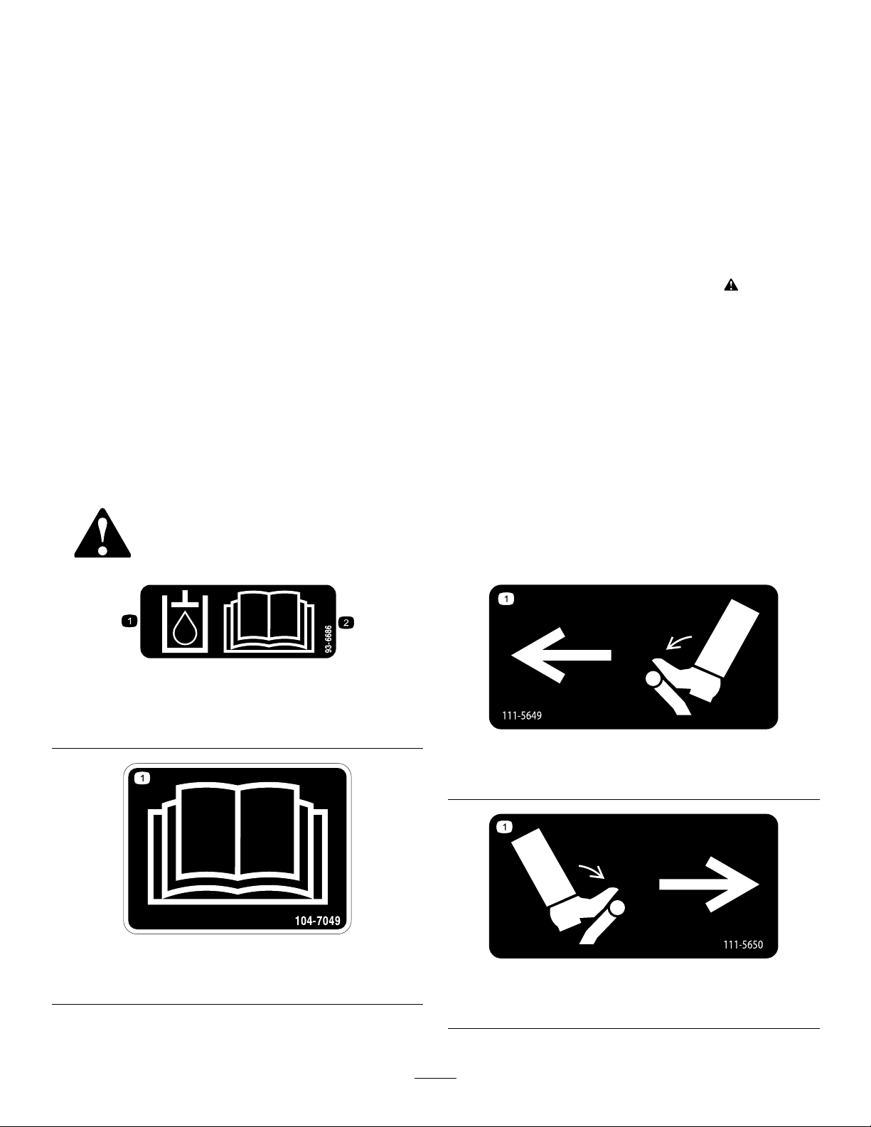
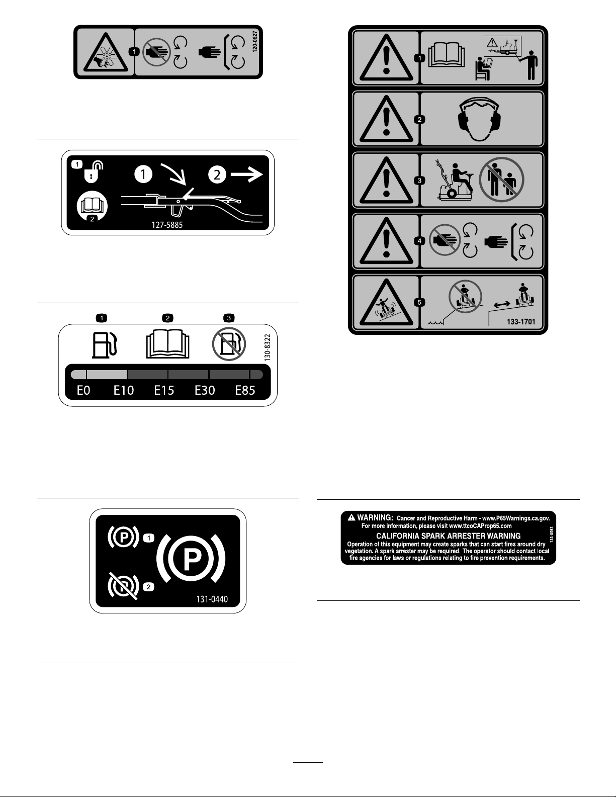
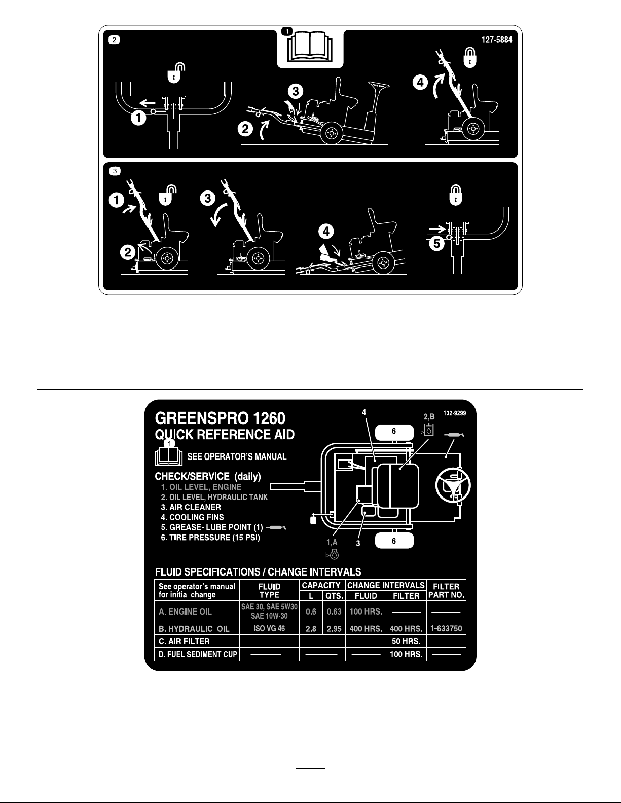
SafetyandInstructionalDecals..........................4
Setup........................................................................7
1InstallingtheTransportWheels........................8
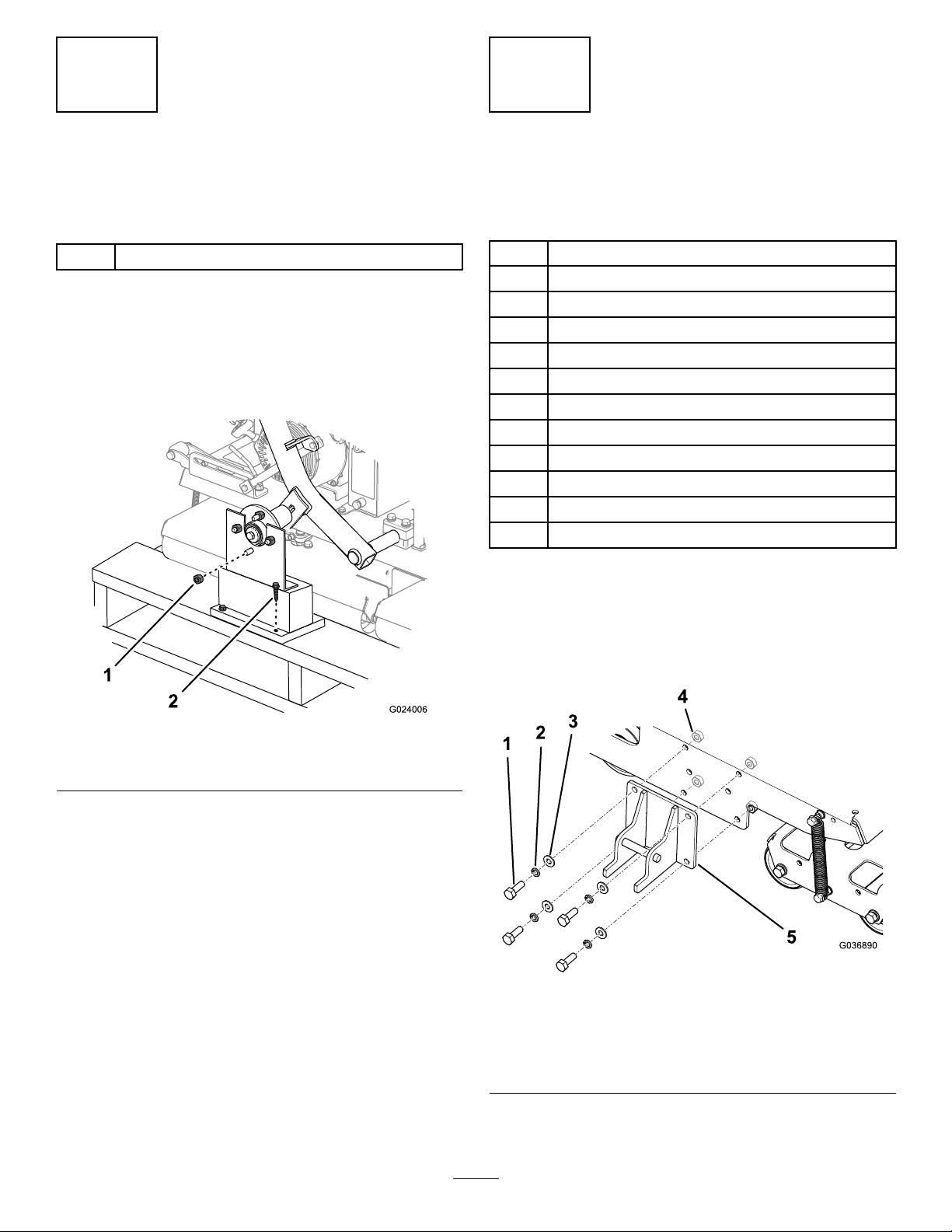
2InstallingtheHitchAssembly...........................8
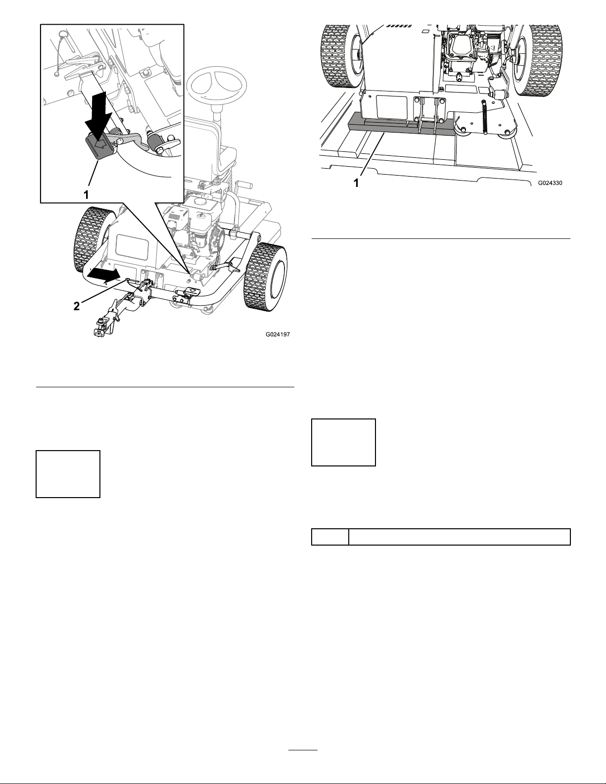
3RemovingtheMachinefromthe
Pallet.............................................................10
4LubricatingtheMachine.................................10
ProductOverview....................................................11
Controls............................................................11
EngineControls............................................12
Specications..................................................13
Attachments/Accessories.................................13
Operation................................................................14
BeforeOperationSafety...................................14
PreparingtoUsetheMachine...........................14
CheckingtheHydraulicHosesand
Fittings..........................................................14
CheckingtheLeveloftheEngineOil.................14
CheckingtheLeveloftheHydraulic
Fluid..............................................................15
CheckingtheTirePressure...............................16
FillingtheFuelTank..........................................17
DuringOperationSafety...................................17
StartingtheEngine...........................................18
ShuttingOfftheEngine.....................................18
CheckingtheSafety-InterlockSystem..............19
AfterOperationSafety......................................19
UsingtheHitchLock.........................................19
TransportingtheMachine.................................20
OperatingtheMachine.....................................21
HaulingtheMachine.........................................21
OperatingTips.................................................21
Maintenance...........................................................22
RecommendedMaintenanceSchedule(s)...........22
NotationforAreasofConcern...........................24
DailyMaintenanceChecklist.............................24
Pre-MaintenanceProcedures..............................25
MaintenanceSafety..........................................25
Lubrication..........................................................25
LubricatingtheDrive-RollerBearing.................25
EngineMaintenance...........................................26
EngineSafety...................................................26
ChangingtheEngineOil...................................26
ServicingtheAirCleaner..................................27
ServicingtheSparkPlug...................................27
CheckingandAdjustingtheValve
Clearance.....................................................28
FuelSystemMaintenance...................................29
CleaningtheSedimentCup..............................29
DriveSystemMaintenance..................................30
HydraulicSystemSafety...................................30
ChangingtheHydraulicFluidandFilter
......................................................................30
BrakeMaintenance.............................................31
CheckingandAdjustingtheParking
Brake............................................................31
Cleaning..............................................................32
Storage...................................................................32
3

Safety
Thismachinehasbeendesignedinaccordancewith
ENISO12100:2010andANSIB71.4-2017.
Important:ForCErequiredregulatorydata,refer
totheDeclarationofConformitysuppliedwith
themachine.
GeneralSafety
Thisproductiscapableofcausingpersonalinjury.
Alwaysfollowallsafetyinstructionstoavoidserious
personalinjury.
Usingthisproductforpurposesotherthanitsintended
usecouldprovedangeroustoyouandbystanders.
•Readandunderstandthecontentsofthis
Operator’sManualbeforestartingtheengine.
•Donotputyourhandsorfeetnearmoving
componentsofthemachine.
•Donotoperatethemachinewithoutallguards
andothersafetyprotectivedevicesinplaceand
workingonthemachine.
•Keepbystandersandpetsasafedistanceaway
fromthemachine.
•Keepchildrenoutoftheoperatingarea.Never
allowchildrentooperatethemachine.
•Stopthemachineandshutofftheenginebefore
servicing,fueling,oruncloggingthemachine.
Improperlyusingormaintainingthismachinecan
resultininjury.T oreducethepotentialforinjury,
complywiththesesafetyinstructionsandalways
payattentiontothesafety-alertsymbol,which
meansCaution,Warning,orDanger—personalsafety
instruction.Failuretocomplywiththeseinstructions
mayresultinpersonalinjuryordeath.
Youcanndadditionalsafetyinformationwhere
neededthroughoutthisOperator’sManual.
SafetyandInstructionalDecals
Safetydecalsandinstructionsareeasilyvisibletotheoperatorandarelocatednearanyarea
ofpotentialdanger.Replaceanydecalthatisdamagedormissing.
decal93-6686
93-6686
1.Hydraulicuid
2.ReadtheOperator'sManual.
decal104-7049
104-7049
1.ReadtheOperator’sManual.
decal111-5649
111-5649
1.Tractionpedal,pushtomoveleft.
decal111-5650
111-5650
1.Tractionpedal,pushtomoveright.
4

decal120-0627
120-0627
1.Cutting/dismembermenthazard,fan—stayawayfrom
movingparts,keepallguardsandshieldsinplace.
decal127-5885
127-5885
1.Hitchunlock—1)push
downonthelatch;2)pull
outthehitch.
2.ReadtheOperator's
Manual.
decal130-8322
130-8322
1.Useonlygasolinethat
contains10%ethanolby
volume(E10)orless.
3.Donotusegasolinethat
containsmorethan10%
ethanolbyvolume(E10).
2.ReadtheOperator's
Manual.
decal131-0440
131-0440
1.Parkingbrake—engage2.Parkingbrake—disengage
decal133-1701
133-1701
1.Warning—readthe
Operator'sManual;do
notoperatethemachine
unlessyouhavereceived
training.
4.Warning—keepaway
frommovingparts;keep
allguardsandshieldsin
place.
2.Warning—wearhearing
protection.
5.Tippinghazard—donot
operatethemachinenear
water;stayawayfrom
embankmentsordropoffs.
3.Warning—keep
bystandersawayfrom
themachine.
decal133-8062
133-8062
5

decal127-5884
127-5884
1.ReadtheOperator’sManual.3.1)Pushthehitchup;2)Releasethelatchlever;3)Pullthe
hitchdown;4)Steponthefootpedaluntilthehitchsnapsinto
place;5)Insertthelockpin.
2.1)Pullthelockpin;2)Tipthemachineup;3)Unlatchthe
hitch;4)Raisethehitchuntiltheleverlatchlocksintheslide.
decal132-9299
132-9299
1.ReadtheOperator'sManualformoreinformationonmaintainingthemachine.
6

Setup
LooseParts
Usethechartbelowtoverifythatallpartshavebeenshipped.
ProcedureDescriptionQty.Use
1Transportwheel2Installthetransportwheels.
Lockbracket1
Bolt(M10x30mm)4
Lockwasher(M10)4
Washer(M10)6
Nut(M10)4
Hitchassembly1
Bolt(M10x100mm)1
Locknut(M10)1
Bolt(M12x100mm)1
Washer(M12)2
Locknut(M12)1
2
Spacerwasher(whenapplicable)2
Installthehitchassembly.
3Nopartsrequired–Removethemachinefromthepallet.
4Lubricants(notincluded)–Lubricatethemachine.
MediaandAdditionalParts
DescriptionQty.Use
Operator’sManual1
Engineowner’smanual1Readthemanualsbeforeoperatingthemachine.
CerticateofCompliance1ThecerticateisrequiredforEuropeanCEcompliance.
7

1
InstallingtheTransport
Wheels
Partsneededforthisprocedure:
2Transportwheel
Procedure
1.Removethelugnutssecuringthewheelhubsto
theshippingbrackets(Figure3).Also,remove
thenutsthreadedontothestudofeachwheel
hub.
g024006
Figure3
1.Lugnut2.Shippingbracket
2.Carefullyremovetheshippingbracketsfromthe
crates.
3.Installthetransportwheelsontothewheelhubs
withthelugnuts.Hand-tightenthelugnuts.
Note:Thelugnutswillbetorquedatthe
completionofstep2.
4.Adjustthetirepressureto103kPa(15psi).
2
InstallingtheHitch
Assembly
Partsneededforthisprocedure:
1Lockbracket
4Bolt(M10x30mm)
4Lockwasher(M10)
6Washer(M10)
4Nut(M10)
1Hitchassembly
1Bolt(M10x100mm)
1Locknut(M10)
1Bolt(M12x100mm)
2Washer(M12)
1Locknut(M12)
2Spacerwasher(whenapplicable)
Procedure
1.Installthelockbrackettotheframeofthe
machineasshowninFigure4.
Note:T orquethenutsto52N∙m(38ft-lb).
g036890
Figure4
1.Bolt—M10x30mm(4)4.Nut—M10(4)
2.Lockwasher—M10(4)5.Lockbracket
3.Washer—M10(4)
2.Securethehitchtothehitchpivotbracketwith
theappropriatehardware;refertoFigure5.
8

•Inthefrontholes,useabolt(M10x100
mm),2washers(M10),andalocknut(M10).
•Intherearholes,useabolt(M12x100mm),
2washers(M12),andalocknut(M12).
•Ifyourmachinehasathirdwasherincluded
witheachbolt,usethosewashersasspacers
betweenthehitchandtheinsideofthehitch
pivotbracket(Figure6).
Note:Usetheholesinthehitchpivotbracketto
matchthehitchheightofthetow-vehiclehitch.
g025914
Figure5
1.Hitch5.Washer—M12(2)
2.Hitchpivotbracket6.Bolt(M12)
3.Washer—M10(2)7.Locknut(M12)
4.Bolt(M10)8.Locknut(M10)
g025915
Figure6
1.Spacerwashers
3.Tightenthesmallboltto73N∙m(54ft-lb)and
thelargeboltto126N∙m(93ft-lb).
4.Pushuponthehitchassemblyuntilthelatch
leverisunlockedfromtheslidedetent(Figure7).
g024011
Figure7
1.Latchlever
5.Pullthehitchdown.
6.Steponthehitchpedaluntilthehitchlocksinto
place(Figure8).
9

g024197
Figure8
1.Hitchpedal2.Lockingpin
7.Insertthelockingpin(Figure8).
8.Torquethelugnutsonthetransportwheelsto
108N∙m(80ft-lb).
3
RemovingtheMachine
fromthePallet
NoPartsRequired
Procedure
1.Removethewoodblocksatthehitchendofthe
pallet.
g024330
Figure9
1.Woodblocks
2.Placesomewoodboardsonthegroundatthe
endofthepallet.
Note:Theheightofthewoodboardsshouldbe
slightlylowerthanthepallet.Youcanusepieces
removedfromthesidesand/orendsofthecrate.
3.Carefullyrollthemachineoffthepallet,ontothe
woodboards,andthentotheground.
Important:Ensurethattherollersdonot
contactthepalletasthemachinedropsto
theground.
4.Removeanyremainingpackaging.
4
LubricatingtheMachine
Partsneededforthisprocedure:
–Lubricants(notincluded)
Procedure
Beforeyouoperatethemachine,lubricateittoensure
properoperatingcharacteristics;refertoLubrication
(page25).Failuretoproperlylubricatethemachine
willresultinprematurefailureofcriticalparts.
10

ProductOverview
g036787
Figure10
1.Hitch-locklever7.Motionpedals
2.Hitchlatch8.Tilt-steeringpedal
3.Seat-adjustmentlever9.Hourmeter
4.Parkingbrake10.Latchlever
5.Steeringwheel11.Hitchpedal
6.Lightswitch12.Hitchassembly
g019903
Figure11
1.Sparkplug4.Recoilstarter
2.Mufer5.Recoil-starthandle
3.Aircleaner
Controls
Note:Refertoyourengineowner’smanualfor
completecontrolinformation.
ParkingBrake
Engagetheparkingbraketoallowthemachineto
start.T oengagetheparkingbrake(Figure12),pull
backontheparking-brakelever.T odisengageit,
pushtheleverforward.
g027608
Figure12
1.Parking
brake—disengaged
2.Parkingbrake—engaged
SteeringWheel
Turnthesteeringwheel(Figure10)clockwisetoturn
themachineintheforwarddirection.
Turnthesteeringwheelcounterclockwisetoturnthe
machineintherearwarddirection.
Note:Asthedirectionchangesattheendofevery
run,youwillneedtopracticewiththemachineto
becomeaccustomedtothesteering.
Thesteeringwheelcontrolstheangleofthesmoothing
rollers,whichinturnsteerthemachine.Theamount
thewheelcanbeturnedislimited,sotheturningcircle
ofthemachineislarge.
Tilt-SteeringPedal
Totiltthesteeringwheeltowardyou,pressthefoot
pedal(Figure10)down,pullthesteeringtowertoward
youtothemostcomfortableposition,andreleasethe
pedal.
MotionPedals
Thefoot-operatedmotionpedals(Figure10),located
toeithersideofthebaseofthesteeringwheel,
controlthemotionofthedriveroller.Thepedalsare
11

connectedsothattheycannotbothbepresseddown
atthesametime,youcanpressonly1pedalata
time.Ifyoupressdowntherightpedal,themachine
movestotheright,andifyoupressdowntheleft
pedal,themachinemovestotheleft.Thefurtheryou
pressapedal,thefasteryourspeedinthatdirection.
Note:Cometoafullstopbeforechangingthe
directionofthemachine;donotabruptlychangethe
pedaldirection.Doingsooverstressesthetraction
driveline,resultinginprematurefailureofdrive-line
components.Actuatethepedalsslowlyandsmoothly
toavoidpotentialturfscufngdamageaswellas
drive-linecomponentdamage.
Whenoperatingthemachineonhills,ensurethat
thedriverollerisonthedownhillsideforadequate
traction.Failuretodosomayresultinturfdamage.
HitchAssembly
Usethehitchassembly(Figure10)totowthemachine
andtolower/raisethetransportwheels.
Seat-AdjustmentLever
Youcanmovetheseatforwardorbackward.Rotate
theseat-adjustmentlever(Figure10)upwardand
slidetheseatforwardorbackward,thenreleasethe
lever.
Armrest-AdjustmentBolts
Youcanadjusteacharmrestbyturningtherespective
adjustmentbolt(Figure13).
g038454
Figure13
1.Adjustmentbolt
LightSwitch
Usethelightswitchtoturnthelightsonandoff(Figure
10).
HourMeter
Thehourmeter(Figure10)indicatesthetotalhoursof
machineoperation.
EngineControls
On/OffSwitch
TheOn/Offswitch(Figure14)allowstheoperatorof
themachinetostartandshutofftheengine.This
switchislocatedonthefrontoftheengine.Rotatethe
On/OffswitchtotheONpositiontostartandrunthe
engine.RotatetheOn/OffswitchtotheOFFposition
toshutofftheengine.
g021103
Figure14
1.OFFposition2.ONposition
ChokeLever
Thechokelever(Figure15)isrequiredwhenstarting
acoldengine.Beforepullingtherecoil-starthandle,
movethechokelevertotheCLOSEDposition.Once
theengineisrunning,movethechokelevertothe
OPENposition.Donotusethechokeiftheengineis
alreadywarmeduporiftheairtemperatureishigh.
12

g019815
Figure15
1.Chokelever3.Throttlelever
2.Fuel-shutoffvalve
ThrottleLever
Thethrottlelever(Figure15)islocatednexttothe
chokecontrol;itcontrolsthespeedoftheengine
andthereforecontrolsthespeedofthemachine.For
bestrollingperformance,setthiscontroltotheFAST
position.
Fuel-ShutoffValve
Thefuel-shutoffvalve(Figure15)islocated
underneaththechokelever.Moveittotheopen
positionbeforeattemptingtostarttheengine.Once
youhavenishedusingthemachineandyouhave
turnedtheengineoff,movethefuel-shutoffvalveto
theCLOSEDposition.
Recoil-StartHandle
Tostarttheengine,pulltherecoil-starthandle(Figure
11)quicklytoturntheengineover.Thecontrolson
theenginedescribedabovemustallbesetcorrectly
fortheenginetostart.
Oil-LevelSwitch
Theoil-levelswitchislocatedinsidetheengine;it
preventstheenginefromrunningiftheoillevelfalls
belowthesafeoperatinglimit.
Specications
Weight308kg(679lb)
Length136cm(53.5inches)
Width122cm(48.0inches)
Height107cm(42.2inches)
Maximumspeed12.8km/h(8mph)@3600rpm
Attachments/Accessories
AselectionofToroapprovedattachmentsand
accessoriesisavailableforusewiththemachine
toenhanceandexpanditscapabilities.Contact
yourAuthorizedServiceDealerorauthorizedToro
distributororgotowww.Toro.comforalistofall
approvedattachmentsandaccessories.
Toensureoptimumperformanceandcontinuedsafety
certicationofthemachine,useonlygenuineT oro
replacementpartsandaccessories.Replacement
partsandaccessoriesmadebyothermanufacturers
couldbedangerous,andsuchusecouldvoidthe
productwarranty.
13

Operation
Note:Determinetheleftandrightsidesofthe
machinefromthenormaloperatingposition.
BeforeOperationSafety
GeneralSafety
•Neverallowchildrenoruntrainedpeopleto
operateorservicethemachine.Localregulations
mayrestricttheageoftheoperator.Theowner
isresponsiblefortrainingalloperatorsand
mechanics.
•Becomefamiliarwiththesafeoperationofthe
equipment,operatorcontrols,andsafetysigns.
•Knowhowtostopthemachineandenginequickly.
•Checkthatoperator-presencecontrols,safety
switches,andshieldsareattachedandfunctioning
properly.Donotoperatethemachineunlessthey
arefunctioningproperly.
•Beforeoperating,alwaysinspectthemachine
toensurethatthecomponentsandfasteners
areingoodworkingcondition.Replacewornor
damagedcomponentsandfasteners.
•Inspecttheareawhereyouwillusethemachine
andremoveallobjectsthatthemachinecould
throw.
FuelSafety
•Useextremecareinhandlingfuel.Itisammable
anditsvaporsareexplosive.
•Extinguishallcigarettes,cigars,pipes,andother
sourcesofignition.
•Useonlyanapprovedfuelcontainer.
•Donotremovethefuelcaporllthefueltank
whiletheengineisrunningorhot.
•Donotaddordrainfuelinanenclosedspace.
•Donotstorethemachineorfuelcontainerwhere
thereisanopename,spark,orpilotlight,such
asonawaterheaterorotherappliance.
•Ifyouspillfuel,donotattempttostarttheengine;
avoidcreatinganysourceofignitionuntilthefuel
vaporshavedissipated.
PreparingtoUsethe
Machine
1.Clearanydebrisfromaboveandunderneath
themachine.
2.Ensurethatallscheduledmaintenancehas
beencompleted.
3.Ensurethatallguardsandcoversareinplace
andrmlyattached.
4.Checktheleveloftheengineoil.
5.Ensurethatthereisfuelinthefueltank.
6.Ensurethattheparkingbrakeisengaged.
7.Liftthetransportwheelsclearofthegroundand
ensurethattheyarelockedinplace.
CheckingtheHydraulic
HosesandFittings
ServiceInterval:Beforeeachuseordaily
Checkthehydraulicsystemforleaks,loosemounting
supports,wear,loosettings,weatherdeterioration,
andchemicaldeterioration.Makeallnecessary
repairsbeforeoperatingthemachine.
WARNING
Hydraulicuidescapingunderpressurecan
penetrateskinandcauseinjury.
•Seekimmediatemedicalattentionifuid
isinjectedintoskin.
•Makesurethatallhydraulicuidhoses
andlinesareingoodconditionandall
hydraulicconnectionsandttingsaretight
beforeapplyingpressuretothehydraulic
system.
•Keepyourbodyandhandsawayfrom
pinholeleaksornozzlesthateject
high-pressurehydraulicuid.
•Usecardboardorpapertondhydraulic
leaks.
•Safelyrelieveallpressureinthehydraulic
systembeforeperforminganyworkonthe
hydraulicsystem.
CheckingtheLevelofthe
EngineOil
ServiceInterval:Beforeeachuseordaily
Note:Thebesttimetochecktheengineoiliswhen
theengineiscoolbeforeithasbeenstartedforthe
day.Ifithasalreadybeenrun,allowtheoiltodrain
backdowntothesumpforatleast10minutesbefore
checkingit.
CrankcaseCapacity:0.60L(0.63USqt)
Type:APlserviceclassicationSL,SM,SN,orhigher
Viscosity:selectaccordingtoambienttemperature;
refertoFigure16.
14

g018667
Figure16
1.Positionthemachineonaatsurfacesothat
theengineislevel.
2.Shutofftheengine,waitforittocool,andclean
theareaaroundtheoil-llercap/dipstick(Figure
17).
g024013
Figure17
1.Oil-llercap/dipstick2.Fillerport
3.Removetheoil-llercap/dipstickbyrotatingit
counterclockwise.
4.Wipetheoil-llercap/dipstickcleanandinsertit
intothellerport.
Note:Donotscrewthedipstickintotheport.
5.Removethedipstickandchecktheoillevel.
Note:Iftheoillevelisnearorbelowthe
lower-limitmarkonthedipstick,addonlyenough
oiltoraiseleveltotheupper-limitmark(bottom
edgeoftheoil-llhole);refertoFigure18.Check
theoillevelagain.Donotoverllthecrankcase.
g024239
Figure18
1.Upperlimit2.Lowerlimit
6.Installtheoil-llercap/dipstickandwipeupany
spilledoil.
Note:Runningtheenginewiththeoillevelatthe
lowerlimitmayinducenuisanceengineshutdownsin
operatingsituationswherethemachineisswitching
directiononaninclineordescent.
CheckingtheLevelofthe
HydraulicFluid
ServiceInterval:Beforeeachuseordaily
Thehydraulicsystemislledatthefactorywith
high-qualityhydraulicuid.Checkthelevelofthe
hydraulicuidbeforetheengineisrststarted
anddailythereafter.
Note:Beforeworkingonanypartofthehydraulic
drivesystem,shutofftheenginetodepressurizethe
system.Beforestartingtheengineafterhydraulic
systemmaintenance,andpressurizingthehydraulic
lines,checkallhosesandconnectorsfordamageand
toensurethattheyaretight.Replaceanydamaged
hosesandtightenanyloosecouplingsasrequired.
RecommendedHydraulicFluid:ToroPremiumAll
SeasonHydraulicFluid(Availablein5USgallon
pailsor55USgallondrums.Refertothepartscatalog
orcontactyourAuthorizedT oroDistributorforpart
numbers.)
Alternativeuids:IftheT orouidisnotavailable,
otherconventional,petroleum-baseduidsmaybe
used,providedtheymeetallofthefollowingmaterial
propertiesandindustryspecications.Checkwith
youroilsuppliertoseewhethertheoilmeetsthese
specications.
Note:T orowillnotassumeresponsibilityfordamage
causedbyimpropersubstitutions,souseonly
productsfromreputablemanufacturerswhowillstand
behindtheirrecommendation.
15

HighViscosityIndex/LowPourPointAnti-wearHydraulic
Fluid,ISOVG46Multigrade
MaterialProperties:
Viscosity,ASTMD445cSt@40°C(104°F)44to48
cSt@100°C(212°F)7.9to9.1
ViscosityIndexASTMD2270140orhigher
PourPoint,ASTMD97-37°Cto-45°C(-34°Fto-49°F)
FZG,Failstage11orbetter
Watercontent(newuid):500ppm(maximum)
IndustrySpecications:
VickersI-286-S,VickersM-2950-S,DenisonHF-0,
Vickers35VQ25(EatonATS373-C)
Theproperhydraulicuidsmustbespeciedfor
mobilemachinery(asopposedtoindustrialplant
usage),multiweight-type,withZnDTPorZDDP
anti-wearadditivepackage(notanashless-typeuid).
Note:Manyhydraulicuidsarealmostcolorless,
makingitdifculttospotleaks.Areddyeadditivefor
thehydraulicsystemuidisavailablein20ml(2/3
oz)bottles.Onebottleissufcientfor15to22L
(4to6USgallons)ofhydraulicuid.OrderPartNo.
44-2500fromyourAuthorizedToroDistributor.
1.Positionthemachineonalevelsurface,shutoff
theengine,andengagetheparkingbrake.
2.Pullbackontheseatlatch,andtiptheseat
forward(Figure19).
g027775
Figure19
1.Seatlatch2.Latchpin
3.Removethehydraulic-tankcapandcheckthe
uidlevelonthedipstick(Figure20).
Note:Theuidlevelshouldbebetweenthe
upperlimitandthelowerlimitonthedipstick
(Figure21).
g036795
Figure20
1.Hydraulic-tankcap
g036796
Figure21
1.Upperlimit2.Lowerlimit
4.Iftheuidlevelislow,addenoughuidtoraise
ittotheproperlevel.
5.Installthetankcap.
6.Wipeupanyspilleduid.
7.Lowerandlatchtheseat.
CheckingtheTirePressure
Makesurethatthetransporttiresareinatedto103
kPa(15psi).
16

FillingtheFuelTank
•Forbestresults,useonlyclean,fresh(lessthan
30daysold),unleadedgasolinewithanoctane
ratingof87orhigher((R+M)/2ratingmethod).
•Ethanol:Gasolinewithupto10%ethanol
(gasohol)or15%MTBE(methyltertiarybutyl
ether)byvolumeisacceptable.EthanolandMTBE
arenotthesame.Gasolinewith15%ethanol
(E15)byvolumeisnotapprovedforuse.Never
usegasolinethatcontainsmorethan10%ethanol
byvolume,suchasE15(contains15%ethanol),
E20(contains20%ethanol),orE85(contains85%
ethanol).Usingunapprovedgasolinemaycause
performanceproblemsand/orenginedamage,
whichmaynotbecoveredunderwarranty.
•Donotusegasolinecontainingmethanol.
•Donotstorefueleitherinthefueltankorfuel
containersoverthewinterunlessafuelstabilizer
isused
•Donotaddoiltogasoline.
Fuel-TankCapacity:3.6L(0.95USgallons)
1.Cleanaroundthefuel-tankcapandremovethe
capfromthetank(Figure22).Usingunleaded
(87pumpoctaneminimum)gasoline,llthefuel
tanktoapproximately25mm(1inch)belowthe
topofthetanktoallowforfuelexpansion.
Important:Donotoverllthetank.Adding
fuelinexcessoftheprescribedlevelwill
resultinenginefailureduetosaturation
ofthevaporrecoverysystem,resulting
inengineperformancefailure.Thisis
notawarrantablefailureandwillrequire
replacementofthefuel-tankcap.
Important:Neverusemethanol,gasoline
containingmethanol,gasoholcontaining
morethan10%ethanol,gasolineadditives,
premiumgasoline,orwhitegasbecausethe
fuelsystemcouldbedamaged.Donotmix
oilwithgasoline.
g028433
Figure22
1.Maximumfuellevel
2.Installthefuel-tankcapandwipeupanyspilled
fuel.
DuringOperationSafety
GeneralSafety
•Theowner/operatorcanpreventandisresponsible
foraccidentsthatmaycausepersonalinjuryor
propertydamage.
•Wearappropriateclothing,includingeye
protection;slip-resistant,substantialfoot
protection;longpants;andhearingprotection.Tie
backlonghairanddonotwearloosejewelry.
•Donotoperatethemachinewhileill,tired,or
undertheinuenceofalcoholordrugs.
•Nevercarrypassengersonthemachineandkeep
bystandersandpetsawayfromthemachine
duringoperation.
•Operatethemachineonlyingoodvisibilitytoavoid
holesorhiddenhazards.
•Avoidoperatingonwetgrass.Reducedtraction
couldcausethemachinetoslide.
•Beforeyoustarttheengine,ensurethatalldrives
areinneutral,theparkingbrakeisengaged,and
youareintheoperatingposition.
17

•Lookbehindanddownbeforebackinguptobe
sureofaclearpath.
•Usecarewhenapproachingblindcorners,shrubs,
trees,orotherobjectsthatmayobscureyour
vision.
•Donotoperateneardrop-offs,ditches,or
embankments.Themachinecouldsuddenlyroll
overifanedgegivesway.
•Stopthemachineandinspecttheattachment
afterstrikinganobjectorifthereisanabnormal
vibrationinthemachine.Makeallnecessary
repairsbeforeresumingoperation.
•Slowdownandusecautionwhenmakingturns
andcrossingroadsandsidewalkswiththe
machine.Alwaysyieldtheright-of-way.
•Neverrunanengineinanareawhereexhaust
gassesareenclosed.
•Neverleavearunningmachineunattended.
•Beforeleavingtheoperatingposition,dothe
following:
–Parkthemachineonlevelground.
–Engagetheparkingbrake.
–Shutofftheengine.
–Waitforallmovingpartstostop.
•Donotoperatethemachinewhenthereistherisk
oflightning.
•Donotusethemachineasatowingvehicle.
•Useaccessories,attachments,andreplacement
partsapprovedbyTheT oro®Companyonly.
•Keephandsandfeetawayfromtherollers.
•Usecarewhenconnectinganddisconnectingthe
machinetoandfromthetowvehicle.
SlopeSafety
•Establishyourownproceduresandrulesfor
operatingonslopes.Theseproceduresmust
includesurveyingthesitetodeterminewhich
slopesaresafeformachineoperation.Always
usecommonsenseandgoodjudgmentwhen
performingthissurvey.
•Slopesareamajorfactorrelatedtolossofcontrol
androlloveraccidents,whichcanresultinsevere
injuryordeath.Theoperatorisresponsiblefor
safeslopeoperation.Operatingthemachineon
anysloperequiresextracaution.
•Operatethemachineatalowerspeedwhenyou
areonaslope.
•Ifyoufeeluneasyoperatingthemachineona
slope,donotdoit.
•Watchforholes,ruts,bumps,rocks,orother
hiddenobjects.Uneventerraincouldoverturnthe
machine.Tallgrasscanhideobstacles.
•Choosealowgroundspeedsothatyoudonot
needtostoporshiftwhileonaslope.
•Arollovercanoccurbeforethetireslosetraction.
•Avoidoperatingthemachineonwetgrass.Rollers
maylosetraction,regardlessofwhetherthe
brakesareavailableandfunctioning.
•Avoidstarting,stopping,orturningthemachine
onaslope.
•Keepallmovementonslopesslowandgradual.
Donotsuddenlychangethespeedordirectionof
themachine.
StartingtheEngine
Note:Makesurethatthespark-plugwireis
connectedtothesparkplug.
1.Ensurethattheparkingbrakeisengagedand
thatthemotionpedalsareintheNEUTRAL
position.
2.TurntheOn/OffswitchtotheONposition.
3.Turnthefuel-shutoffvalvetotheOPENposition.
4.MovethechokelevertotheONpositionwhen
startingacoldengine.
Note:Thechokemaynotberequiredwhen
startingawarmengine.
5.MovethethrottlecontroltotheFASTposition.
6.Standattherearofthemachine,pullthe
recoil-starthandleoutuntilpositiveengagement
results;thenpullitvigorouslytostarttheengine.
Important:Donotpulltherecoilropeto
thelimitorletgoofthestarterhandlewhen
theropeispulledout,becausetherope
maybreakortherecoilassemblymaybe
damaged.
7.Whentheenginehasstarted,pushthechoke
levertotheOFFposition.
8.MovethethrottlelevertotheFASTposition,for
bestrollerperformance.
ShuttingOfftheEngine
1.Afteroperatingthemachine,returnthemotion
pedalstotheNEUTRALpositionandengagethe
parkingbrake.
2.Turntheenginespeedtoidle,andallowittorun
for10to20seconds.
3.TurntheOn/OffswitchtotheOFFposition.
4.Turnthefuel-shutoffvalvetotheCLOSED
position.
18

Checkingthe
Safety-InterlockSystem
CAUTION
Ifthesafety-interlockswitchesare
disconnectedordamaged,themachinecould
operateunexpectedly,causingpersonal
injury.
•Donottamperwiththeinterlockswitches.
•Checktheoperationoftheinterlock
switchesdaily,andreplaceanydamaged
switchesbeforeoperatingthemachine.
Important:Ifthesafety-interlocksystemdoesnot
operateasdescribedbelow,haveanAuthorized
ToroDistributorrepairitimmediately.
1.Engagetheparkingbrake,ensurethatthe
motionpedalsareintheNEUTRALposition,and
starttheengine.
2.Sitontheseat.
3.Withtheparkingbrakeengaged,gentlypressa
motionpedaldown;theengineshouldshutoff
afterapproximately1second.
4.Withtheenginerunningandthebrake
disengaged,standupandverifythattheengine
shutsoffafter1second.
Note:Thesafety-interlocksystemisalsodesigned
toshutofftheengineiftheoperatorrisesofftheseat
whilethemachineismoving.
AfterOperationSafety
•Parkthemachineonalevelsurface;engagethe
parkingbrakeorchockthewheelsasrequired;
shutofftheengine;andwaitforallmovementto
stopbeforeleavingthemachine.
•Cleangrassanddebrisfromthemuferand
enginecompartmenttohelppreventres.Clean
upoilorfuelspills.
•Allowtheenginetocoolbeforestoringthemachine
inanyenclosure.
•Shutoffthefuelbeforestoringortransportingthe
machine.
•Neverstorethemachineorfuelcontainerwhere
thereisanopename,spark,orpilotlight,such
asonawaterheateroronotherappliances.
•Keepallpartsofthemachineingoodworking
conditionandallhardwaretightened.
•Replaceallworn,damaged,ormissingdecals.
UsingtheHitchLock
ConnectingtheMachinetothe
TowVehicle
Pushdownonthehitch-lockleverwhileinsertingthe
hitchassemblyontothetow-vehiclehitch.Release
theleverwhenthehitchandthehitchassemblyare
aligned(Figure23).
Important:EnsurethattheleverreturnstotheUp
positionandthatthehitchandthehitchassembly
areengaged.
g028434
Figure23
1.Hitchassembly(forward)3.Hitchassembly
(backward)
2.Hitch-locklever(up)4.Hitch-locklever(down)
DisconnectingtheMachinefrom
theTowVehicle
Parkthemachineonlevelgroundandchockthe
wheels.
Pushdownonthehitch-lockleverwhileremoving
thehitchassemblyfromthetow-vehiclehitch(Figure
23).Releasethelatchwhenthehitchandthehitch
assemblyaredisengaged.
19

TransportingtheMachine
1.Drivethemachinetothetransportvehicle.
2.Engagetheparkingbrake.
3.Movethethrottlelevertothelow-speedposition,
andallowtheenginetorunfor10to20seconds.
4.TurntheOn/OffswitchtotheOFFposition.
5.Turnthefuel-shutoffvalvetotheCLOSED
position.
6.Raisethemachineontothetransportwheelsas
follows:
A.Pushuponthehitchassemblyuntilthe
latchleverisunlockedfromtheslidedetent
(Figure24).
g024011
Figure24
1.Latchlever
B.Liftthelatchleversothatitslidesfreely,
andpullthehitchdown.
g024010
Figure25
C.Steponthehitchpedaluntilthehitchlocks
intoplace(Figure26).
g024197
Figure26
1.Hitchpedal2.Lockingpin
D.Insertthelockingpin(Figure26).
7.Lowerthemachineontotherollersasfollows:
A.Removethelockingpin(Figure27).
20
This manual suits for next models
3
Table of contents
Other Toro Lawn Mower manuals

Toro
Toro Z Master 8000 Series Manual

Toro
Toro Reelmaster 3555 Series User manual

Toro
Toro Greensmaster TriFlex 3300 User manual

Toro
Toro Recycler 20960 User manual

Toro
Toro 74824 User manual

Toro
Toro 30074 User manual

Toro
Toro 30696 User manual

Toro
Toro 70131 User manual

Toro
Toro Reelmaster Edge Series User manual

Toro
Toro Super Recycler 20381 User manual

Toro
Toro Recycler 20370 User manual

Toro
Toro 30140 User manual

Toro
Toro 30411 User manual

Toro
Toro Recycler 20960 User manual

Toro
Toro 30555 User manual

Toro
Toro Recycler S55OST User manual

Toro
Toro 74904 User manual

Toro
Toro 74228 User manual

Toro
Toro 74295 User manual

Toro
Toro 30223TE GROUNDSMASTER 223D User manual