Toro Groundsmaster 328-D 30630 User manual

Form No. 3325-413 Rev A
Operator’s Manual
®
Groundsmaster®328-D
Traction Unit
Model No. 30630—210000001 and Up
English

Contents
Contents 2
Introduction 3
Safety 4
Safe Operating Practices 4
Safety and Instruction Decals 8
Specifications 11
Before Operating 13
Hood Prop 13
Check the Engine Oil 13
Filling the Fuel Tank 13
Check the Cooling System 14
Checking the Hydraulic System Oil 14
Operation 16
Controls 16
Starting/Stopping the engine 18
Bleeding the Fuel System 19
Checking the Interlock Switches 19
Pushing or Towing the Traction Unit 20
Operating Characteristics 20
Maintenance 22
Recommended Maintenance Schedule 22
Daily Maintenance Checklist 23
Lubricating the Machine 23
General Air Cleaner Maintenance 24
Servicing the Air Cleaner 24
Cleaning the Radiator and Screen 25
Changing Engine Oil and Filter 25
Servicing the Fuel System 26
Cleaning Radiator and Screen 27
Changing Coolant in the Cooling System 27
Servicing the Engine Belts 28
Adjusting the Throttle 29
Adjusting the Traction Control Rod 29
Adjusting the Traction Pedal Friction Wheel 30
Adjusting the Traction Drive for Neutral 30
Adjusting the Traction Interlock Switch 31
Replacing the Power Take-Off Switch 32
Correcting Power Take-Off Drive
Belt Slippage 32
Adjusting the Parking Brake Interlock
Switch 32
Adjusting the Tilt Steering Control 33
Adjusting Rear Wheel Toe-In 33
Adjusting the Rear Wheel Bearings 34
Adjusting the Brakes 34
Adjusting the Lift Lever Latch 35
Replacing the Hydraulic Oil Filter 36
Changing the Hydraulic System Oil 36
Fuses 37
Servicing the Battery 37
Seasonal Storage 38
Traction Unit 38
Engine 38
©2001 by The Toro Company
8111 Lyndale Avenue South
Bloomington, MN 55420-1196
All Rights Reserved
2

Introduction
Read this manual carefully to learn how to operate
and maintain your product properly. The information
in this manual can help you and others avoid injury
and product damage. Although Toro designs and
produces safe products, you are responsible for
operating the product properly and safely.
Whenever you need service, genuine Toro parts, or
additional information, contact an Authorized Service
Dealer or Toro Customer Service and have the model
and serial numbers of your product ready. Figure 1
illustrates the location of the model and serial
numbers on the product.
Figure 1
1. Location of the model and serial numbers
Write the product model and serial numbers in the
space below:
This manual identifies potential hazards and has
special safety messages that help you and others avoid
personal injury and even death. Danger, Warning, and
Caution are signal words that identify the level of
hazard. However, regardless of the hazard, be
extremely careful.
Danger signals an extreme hazard that will cause
serious injury or death if you do not follow the
recommended precautions.
Warning signals a hazard that may cause serious
injury or death if you do not follow the recommended
precautions.
Caution signals a hazard that may cause minor or
moderate injury if you do not follow the
recommended precautions.
This manual uses two additional words to highlight
information.
calls attention to special mechanical
information and Note: emphasizes general
information worthy of special attention.
Important
3
Model No. __________________________
Serial No. ___________________________
1

Improper use or maintenance by the operator or owner
can result in injury. To reduce the potential for injury,
comply with these safety instructions and always pay
attention to the safety alert symbol, which means
CAUTION, WARNING, or DANGER—“personal
safety instruction.” Failure to comply with the
instruction may result in personal injury or death.
Safe Operating Practices
The following instructions are from ANSI standard
B71.4—1999.
Training
• Read the operator’s manual and other training
material. If the operator(s) or mechanic(s)
cannot read English it is the owner’s
responsibility to explain this material to them.
• Become familiar with the safe operation of the
equipment, operator controls, and safety signs.
• All operators and mechanics should be trained.
The owner is responsible for training the users.
• Never let children or untrained people operate or
service the equipment. Local regulations may
restrict the age of the operator.
• The owner/user can prevent and is responsible
for accidents or injuries occurring to himself or
herself, other people or property.
Preparation
• Evaluate the terrain to determine the necessary
accessories and attachments to properly and
safely perform the job. Only use accessories and
attachments approved by the manufacturer.
• Wear appropriate clothing including hardhat,
safety glasses and ear protection. Long hair, loose
clothing or jewelry may get tangled in moving
parts.
• Inspect the area where the equipment will be
used and remove all objects such as rocks, toys
and wire that can be thrown by the machine.
• Use extra care when handling gasoline and other
fuels. They are flammable and vapors are
explosive.
– Use only an approved container.
– Never remove the fuel cap or add fuel with
the engine running. Let the engine cool
before refueling. Do not smoke.
– Never refuel or drain the machine indoors.
• Check that operator’s presence controls, safety
switches and shields are attached and functioning
properly. Do not operate unless they are
functioning properly.
Operation
• Never run an engine in an enclosed area.
• Only operate in good light, keeping away from
holes and hidden hazards.
• Be sure all drives are in neutral and the parking
brake is engaged before starting the engine. Only
start the engine from the operator’s position. Use
seat belts, if provided.
• Slow down and use extra care on hillsides. Travel
in the recommended direction on hillsides. Turf
conditions can affect the machine’s stability. Use
caution while operating near drop-offs.
• Slow down and use caution when making turns
and when changing directions on slopes.
• Never raise the deck with the blades running.
• Never operate with guards not securely in place.
Be sure all interlocks are attached, adjusted
properly, and functioning property.
• Do not change the engine governor setting or
overspeed the engine.
• Stop on level ground, lower the cutting units,
4
Safety

move the traction pedal to neutral, disengage
drives, engage the parking brake (if provided),
and shut off the engine before leaving the
operator’s position for any reason.
• Stop equipment and inspect the blades after
striking objects or if an abnormal vibration
occurs. Make necessary repairs before resuming
operations.
• Keep your hands and feet away from the cutting
units.
• Look behind and down before backing up to be
sure of a clear path.
• Never carry passengers and keep pets and
bystanders away.
• Slow down and use caution when making turns
and crossing roads and sidewalks. Stop blades if
not mowing.
• Do not operate the mower under the influence of
alcohol or drugs.
• Use care when loading or unloading the machine
into a trailer or truck.
• Use care when approaching blind corners,
shrubs, trees, or other objects that may obscure
vision.
• The operator shall turn on flashing warning
lights, if provided, whenever traveling on a
public road, except where such use is prohibited
by law.
Maintenance and Storage
• Disengage drives, lower the cutting units, move
the traction pedal to neutral, set the parking
brake, stop the engine and remove the key and
disconnect the spark plug wire. Wait for all
movement to stop before adjusting, cleaning or
repairing.
• Clean grass and debris from the cutting units,
drives, mufflers, and engine to help prevent fires.
Clean up oil or fuel spillage.
• Let the engine cool before storing and do not
store it near flame.
• Shut off fuel while storing or transporting. Do
not store fuel near flames or drain indoors.
• Park the machine on level ground. Never let
untrained personnel service the machine.
• Use jack stands to support components when
needed.
• Carefully release pressure from components with
stored energy.
• Disconnect the battery or remove the spark plug
wire before making any repairs. Disconnect the
negative terminal first and the positive last.
Reconnect positive first and negative last.
• Use care when checking blades. Wrap the blades
or wear gloves, and use caution when servicing
them. Only replace blades. Never straighten or
weld them.
• Keep your hands and feet away from moving
parts. If possible, do not make adjustments with
the engine running.
• Charge batteries in an open, well-ventilated area,
away from spark and flames. Unplug the charger
before connecting or disconnecting it from the
battery. Wear protective clothing and use
insulated tools.
• Keep all parts in good working condition and all
hardware tightened. Replace all worn or damaged
decals.
Toro Mower Safety
The following list contains safety information specific
to Toro products or other safety information that you
must know.
This product can amputate hands and feet and throw
objects. Always follow all safety instructions to avoid
5

serious injury or death.
Using this product for purposes other than its intended
use could be dangerous to the user and bystanders.
Operation
• Always wear substantial shoes. Do not operate
the machine while wearing sandals, tennis shoes,
or sneakers.
• Wearing safety shoes and long pants is advisable
and required by some local ordinances and
insurance regulations.
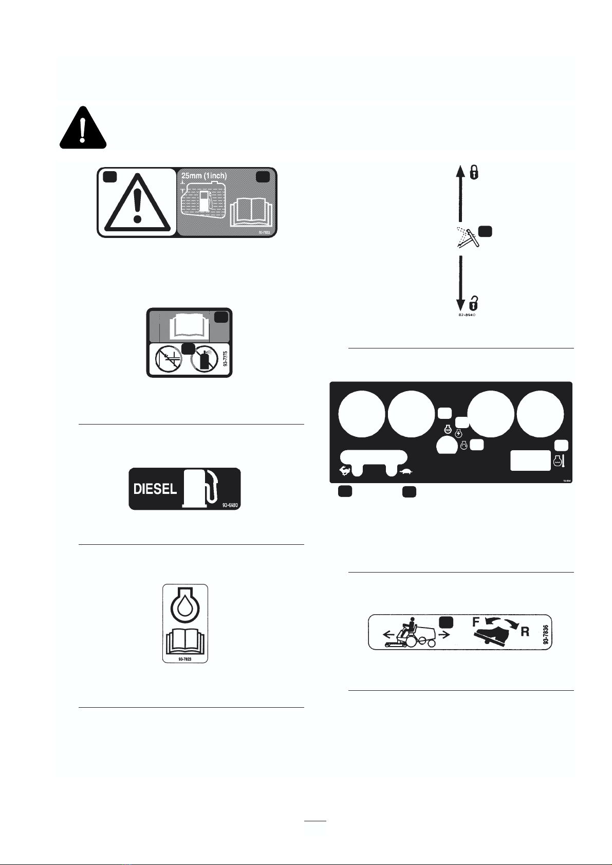
• Fill the fuel tank until the level is 1 in. (25 mm)
below the bottom of the filler neck. Do not
overfill.
• Check the safety interlock switches daily for
proper operation. If a switch should fail, replace
the switch before operating the machine. After
every two years, replace all three interlock
switches in the safety system, regardless of
whether or not they are working properly.
• The grass deflector(s) must always be installed
and in the lowest position on the cutting unit.
• Pay attention when using the machine. To
prevent loss of control:
– Drive slowly.
– Do not drive close to sand traps, ditches,
creeks, or other hazards.
– Reduce speed when making sharp turns.
Avoid sudden stops and starts.
– Lower the cutting unit when going down
slopes.
• Do not touch the engine, radiator, or muffler
while the engine is running or soon after it has
stopped because these areas might burn you.
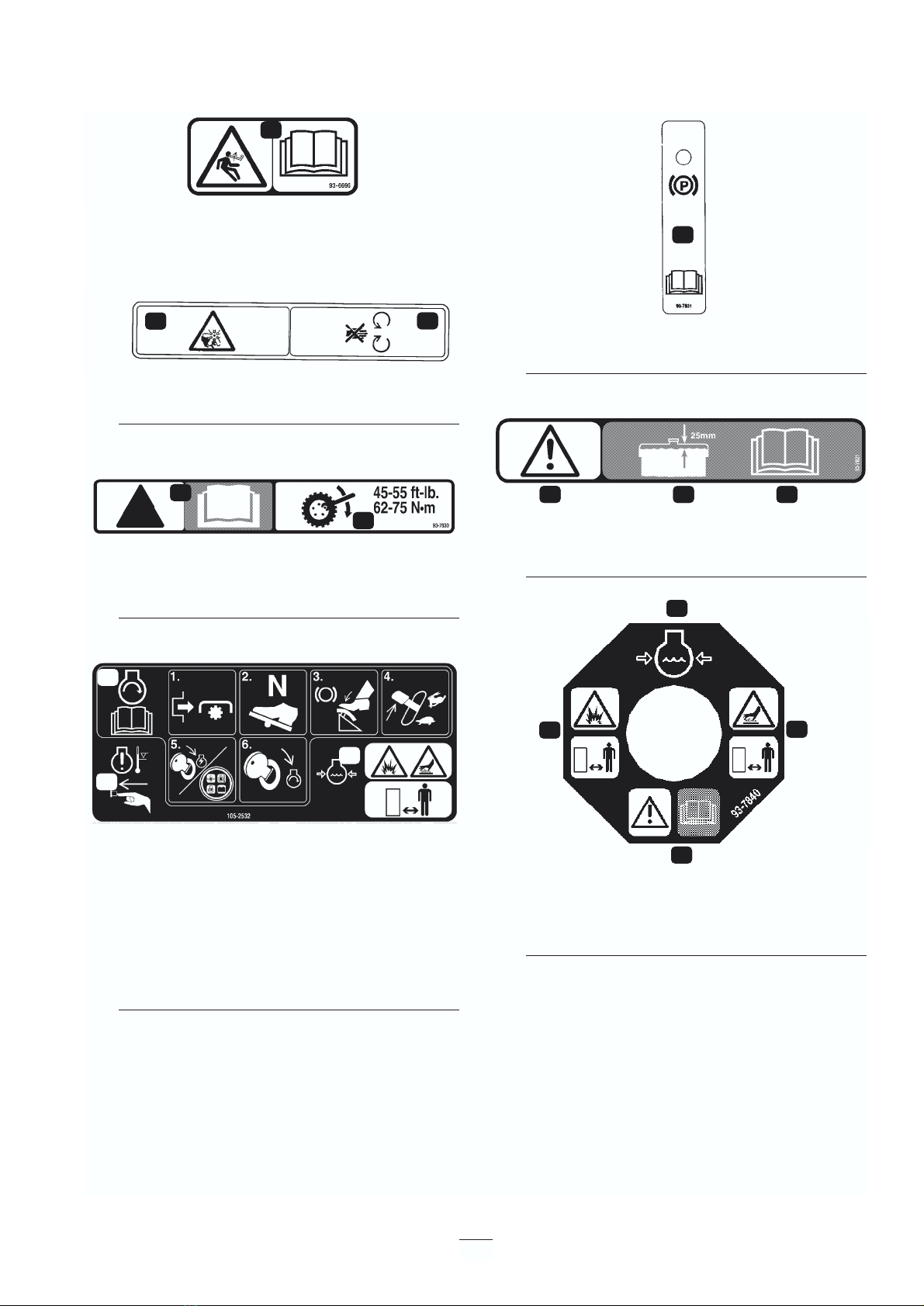
• If a cutting blade strikes a solid object or vibrates
abnormally, disengage the power take off, move
the throttle to Slow, set the parking brake, stop
the engine, and remove the ignition key. Wait for
all motion to stop, and inspect the machine for
damage. Repair or replace any damaged parts
before operating. Ensure that the cutting blades
are in good condition and the blade bolts are
torqued to proper specifications (see the cutting
deck operator’s manual).
• Check carefully for overhead clearances such as
branches, doorways, and electrical wires before
driving under any objects. Do not contact the
objects.
• Make sure that the set belt can be removed
quickly if the machine is driven or rolls into a
pond or lake.
• If the engine stalls or the machine loses headway
and cannot get to the top of a slope, do not turn
the machine around. Always back slowly straight
down the slope.
• If the cutting unit discharge area ever plugs,
disengage the power take off and shut the engine
off before removing the obstruction.
• When operating a 4-wheel drive machine or any
machine on slopes, by banks, or drop offs,
always have the roll-over protection system
installed.
• When operating the machine with the roll-over
protection system, always use the seat belt and
make sure that the seat pivot retaining pin is
installed.
Maintenance and Storage
• Before servicing or making adjustments, stop the
engine and remove the ignition key.
• Ensure that the entire machine is properly
maintained and in good operating condition.
Frequently check all nuts, bolts, and screws.
Check all cutting unit blade bolts frequently to
ensure that they are torqued to proper
specifications (see the cutting deck operator’s
manual).
• Make sure all hydraulic line connectors are tight
and all hydraulic hoses and lines are in good
6

condition before applying pressure to the system.
• Keep your body and hands away from pin hole
leaks or nozzles that eject hydraulic fluid under
high pressure. Use paper or cardboard, not your
hands, to search for leaks. Hydraulic fluid
escaping under pressure can have sufficient force
to penetrate the skin and cause serious injury.
• Before disconnecting or performing any work on
the hydraulic system, all pressure in the system
must be relieved by stopping the engine and
lowering the cutting units.
• If the engine must be running to perform a
maintenance adjustment, keep hands, feet,
clothing, and all body parts away from the
cutting units, attachments, power take off shaft,
and any moving parts.
• Do not overspeed the engine by changing
governor settings. To ensure safety and accuracy,
have an authorized Toro distributor check the
maximum engine speed with a tachometer.
Maximum governed engine speed with no load
should be 3200–3250 RPM.
• The engine must be shut off before checking the
oil or adding oil.
• Periodically inspect the roll bar and roll bar
mounting.
Replace, if necessary. Do not modify roll over
protection frames or structures because they are
specifically designed, sized, located, and tested
for injury reduction. If a rollover occurs, a
modified roll-over protection system will not
provide adequate protection.
• If major repairs are ever needed or if assistance is
desired, contact an authorized Toro distributor.
• For optimum performance and continued safety
certification of the machine, use only genuine
Toro replacement parts and accessories.
Replacement parts and accessories made by other
manufacturers could be dangerous, and such use
could void the product warranty.
7

93-7822
1. Caution—fill the fuel tank to 1 in. (25 mm) below the filler
neck. Read the operator’s manual for further instructions.
93-7275
1. Read the operator’s manual for further instructions.
2. Do not use starting fluid.
93-6680
1. Diesel fuel
93-7823
1. Read the operator’s for further information about engine
oil.
82-8940
1. Locks and unlocks the steering column
105-0056
1. Fast
2. Slow
3. Engine stop
4. Engine run
5. Engine start
6. Temperature
93-7836
1. To move the traction unit forward or backward, depress
the traction pedal.
8
Safety and Instruction Decals
Safety decals and instructions are easily visible to the operator and are located near any area of potential danger.
Replace any decal that is damaged or lost.
1 1
1
1
2
1
1
2
3
4
56
1

93-6696
1. Warning—spring-loaded mechanism. Read the operator’s
manual for further instructions.
93-7272
1. Fan blades can cause injury—stay away from moving
parts.
93-7830
1. Caution—read the operator’s manual for further
instructions.
2. Wheel torque specifications
105-2532
1. To start the engine, disengage the power take off, place
the traction drive in neutral, depress the brake pedal, set
the throttle control half open, turn the ignition key to the
run position. When the glow light turns off, turn the key to
the start position. Read the operator’s manual for further
instructions.
2. Warning—when engine temperature is too high, the
engine will shut off. Depress high temperature reset
before restarting the engine.
3. Warning—coolant is under pressure and could cause
burns. Keep a safe distance away.
93-7831
1. Parking brake—read the operator’s manual for further
instructions.
93-7821
1. Caution
2. Fill coolant to within 1 in. (25 mm) of the top of the tank.
3. Read the operator’s manual for further instructions.
93-7840
1. Coolant level
2. Hot surface—stay away.
3. Warning—read the operator’s manual.
4. Explosion hazard—stay away.
9
1
11
1
2
1
1
3
42
12 3
1
2
3

93-7806
1. Power take off on
2. Power take off off
3. Warning—read the operator’s manual.
4. Cutting hazard to hands or feet—stay away from rotating
blades and moving parts.
5. Throw object hazard—keep bystanders away.
6. Warning—set the parking brake, stop the engine, and
remove the key before leaving the operator’s position.
7. Tipping hazard—when driving down slopes less that 14
degrees, lower the cutting unit to the ground. When
driving down slopes less than 20 degrees, use the roll-
overprotection system, fasten the seat belt, and lower the
cutting unit to the ground.
93-6668
1. The battery contains lead. Do not throw it in the garbage.
93-7816
1. Change the hydraulic filter after first 10 operating hours—
read the operator’s manual for further instructions.
100-6574
1. Hot surface hazard—stay away.
2. Cutting/dismemberment hazard—stay away from moving
parts.
93-7832
1. To move the traction unit forward or backward, depress
the traction pedal.
2. Tipping hazard—when driving down slopes less that 14
degrees, lower the cutting unit to the ground. When
driving down slopes less than 20 degrees, use the roll-
over protections system, fasten the seat belt, and lower
the cutting unit to the ground.
3. Warning—disengage the power take off before raising the
cutting unit.
4. Float cutting unit
5. Lower the cutting unit
6. Raise the cutting unit
10
12
33
5 5 6
6
777
44
1
1
1
22
2
1
2
3
3
4
5
6
2
1

General Specifications
11
Specifications
Note: Specifications and design subject to change without notice.
Engine Kubota, three-cylinder, 4-cycle liquid cooled diesel engine. 26 hp @ 3000. The engine is governed
to 3200–3250 rpm high idle, no load.
Air Cleaner: Heavy-duty, remote mounted
Muffler: Volume equal to approximately five times engine displacement for excellent silencing.
Cooling System The radiator has tube-and-fin construction with the hydraulic oil cooler in the lower tank. Cooling
system capacity is approximately 6 quarts (5.7 l) of a 50% mixture of permanent, ethylene glycol
anti-freeze and water.
Electrical The 12-volt battery has 630-amp., cold cranking performance at 0° F (– 18° C). The fuse block is
located under the control panel.
Fuel System Fuel tank capacity is approximately 6-1⁄2gal. (25 l). 12-volt electric fuel pump . Fuel filter/water
separator with replaceable cartridge is mounted on frame.
Front Axle The heavy-duty Dana GT 20 axle has a 20:9:1 reduction. Axle has automotive-type differential,
bevel gear pinion and ring gear with spur gear reduction from transmission. All axle components
are mounted in tapered roller bearings.
Transmission ASauer-Danfoss, in-line hydrostatic transmission is mounted directly to the front axle and driven
by flexible drive couplings. Operating pressure is 500 to 3000 psi (3447 to 20685 kPa) and normal
charge pressure is 70 to 150 psi (453 to 1034 kPa). The implement relief valve setting is 700 to
900 psi (4826 to 6205 kPa). Displacement is 0.913 cubic inch (15 cm3) per revolution, and
transmission is controlled by foot-actuated pedal. Front axle is the hydraulic fluid reservoir, and its
capacity is 5 quarts (4.7 l) of SAE 10W-30 or 10W-40 engine oil. The 25-micron hydraulic oil
filter is a screw-on replaceable type. For replacement filters, order Toro Part No. 23-9740.
Ground Speed: Speed is infinitely variable from 0 to 9.5 MPH (0 to 15 km/h) forward or reverse.
Tires The two rear tires are 16 x 6.50-8, 4-ply, tubeless ribbed type, on demountable, drop-center
wheels. The two from tires are 23 x 8.50-12, extra traction tread, 4-ply rating, on demountable
wheels. Recommended air pressure for both the front and rear tires is 21 psi (145 kPa).
Brakes The brakes are controlled by three pedals. Two are for steering assist, and are individually
controlled by the driver’s left foot. The third pedal operates both brakes; it is controlled by either
foot. A parking brake latch is provided for the third pedal. Pedals are connected to brakes by a
multi-stranded cable and conduit.
Steering The 15-inch (38 cm) steering wheel is mounted on a steering valve consisting of a control valve
and metering section, which regulates pressure and meters flow to the steering cylinder. Minimum
turning radius is 18 in. from the center of a turn to the closest side of the drive wheel; however,
zero turning radius occurs when individual wheel brakes are used. Steering wheel adjustable fore
and aft for operator comfort.
Main Frame The frame is welded 11-gauge steel, reinforced with square and rectangular tubing.

Width: 46 in. (117 cm)
Length: 91 in. (231 cm)
Height: 50 in. (127 cm)
w/roll-over protection system: 78.5 in. (199 cm)
Dry Weight: 1250 lb. (567 kg)
Wheel Base: 49 in. (124 cm)
Optional Equipment
72” Side Discharge Cutting Unit Model No. 30722
72” Rear Discharge Cutting Unit Model No. 30710
72” Flex Deck Cutting Unit Model No. 30799
Guardian 72 , Recycler Cutting Unit Model No. 30716
Cushion Seat Model No. 30623
Deluxe Suspension Seat Kit (requires Model No. 30625
Model No. 30628)
Model No. 30711
Model No. 30729
Seat Adapter Kit Model No. 30628
Armrest Kit Model No. 30707
Speed Control Kit Model No. 30677
48 in. V-Plow (requires
Model No. 30757) Model No. 30750
V-Plow Mounting Kit
(without tire chains) Model No. 30757
Debris Blower Model No. 30855
Spark Arrestor Screen Part No. 75-6880
Rotary Broom Model No. 30743
Quick Attach Receiver Kit Model No. 30711
(for traction unit)
Quick Attach (for Guardian 72 , Recycler Model No. 30729
Cutting Unit, Model No. 30716
Quick Attach (for 72” Side Discharge Model No. 30719
Cutting Unit, Model No. 30722,
72” Rear Discharge Cutting Unit,
Model No. 30710 and Rotary Broom,
Model No. 30743)
Tire Chains (front) (set of 2) Part No. 11-0390
Wheel Weight Kit (set of 2) Part No. 11-0440
Rear Weight Kit (set of 2) Part No. 24-5780
Rear Weight Kit (set of 1) Part No. 24-5790
4-Ply Wide Tire w/Rim, 23 x 10.5 x Part No. 69-9870
12 (2 required; will not fit with
72” Rear Discharge Deck,
Model No. 30710)
6-Ply Wide Tire w/Rim 23 x 10.5 x Part No. 62-7020
12 (2 required; will not fit with
72” Rear Discharge Deck,
Model No. 30710
Jack Pad Kit Part No. 76-0900
12
Interlock Switches Power take off switch—shuts the engine off when the power take off is engaged with no operator
on the seat. Traction switch—shuts the engine off when the traction pedal is engaged with no
operator on the seat. Seat switch—shuts the engine off if operator leaves the seat without
disengaging the power take off and/or traction pedal. The engine will not start if the power take
off or traction pedal is engaged. Brake switch–shuts the engine off when the power take off or
traction pedal is engaged with the parking brake set.
Hour meter, fuel gauge, oil pressure warning light, charge indicator, ignition switch, engine
coolant temperature warning light, temperature gauge, temperature override switch, glow plug
indicator light, and throttle control are on instrument panel. Hand-operated power take-off lever is
located the right of the seat. Traction pedal for traction operation at the right of the steering
column.
Power Take Off Drive Directly clutched by a belt from the engine’s output shaft. It is clutched by pivoting the shaft
support with a hand-operated lever. Power take-off speed is 1810 rpm@3200 rpm engine speed.
The implement is connected with a high-quality universal joint.
Implement Lift Cutting unit or the implement is lifted by a hydraulic cylinder that has 2-1⁄2in. (64 mm) bore and 3-
1⁄4in. (82 mm) stroke.
Dimensions and Weights (approx.)
Instrument Panel
and Controls

Hood Prop
(Model 30630 only)
1. Position the machine on a level surface.
2. Disengage the hood latch and open the hood.
3. Slide the bottom of the hood prop (Fig. 2) from
the retaining bracket. Lower the hood prop, pivot
it upward, then downward to prop up the hood.
Figure 2
1. Hood prop
Check the Engine Oil
The engine is shipped with 4 qt (=3.8 l) of oil in the
crankcase; however, the oil level must be checked
before and after you first start the engine.
1. Park the machine on a level surface, stop the
engine and remove the key from the ignition
switch. Open the hood and install the hood prop.
2. Remove the dipstick (Fig. 3), wipe it clean and
reinsert it. Remove the dipstick and check the oil
level. The oil level should be to the FULL mark
on the dipstick
3. If the oil level is below the FULL mark, remove
the fill cap and add SAE 10W-30 CD, CE, CF,
CF-4 or CG-4 classification oil until the level
reaches the FULL mark on the dipstick. DO NOT
OVERFILL.
Figure 3
1. Dipstick
Figure 4
1. Oil fill
4. Install the oil fill cap and close the hood.
Filling the Fuel Tank
1. Tip the seat forward and prop it with the support
rod so it cannot fall accidentally. Using a clean
cloth, clean area around the fuel tank cap
(Fig. 5).
2. Remove the cap from the fuel tank and fill the 6-
1⁄2gallon (25 l) tank to within 1 in. (25 mm) from
the top with diesel fuel. Install the fuel tank cap
tightly after filling tank.
13
Before Operating
1
1
1

Figure 5
1. Fuel tank cap
Check the Cooling System
Clean debris from the screen and radiator/oil cooler
daily, more often if conditions are extremely dusty
and dirty.
The cooling system is filled with a 50/50 solution of
water and permanent ethylene glycol anti-freeze.
Check the coolant level in the expansion tank at the
beginning of each day before starting the engine.
Cooling system capacity is 6 quarts (5.6 l).
1. Check the coolant level in the expansion tank. It
should be between the marks on the side of the
tank.
Figure 6
1. Expansion tank
2. If coolant level is low, remove the expansion tank
cap and replenish the system. DO NOT
OVERFILL.
3. Install the expansion tank cap.
Checking the Hydraulic System
Oil
The hydraulic system is designed to operate on any
high-quality detergent oil having the American
Petroleum Institute—API —“ service classification”
SF/CC or CD. Oil viscosity—weight—must be
selected according to anticipated ambient temperature.
14
Under certain conditions, diesel fuel and fuel vapors
are highly flammable and explosive. A fire or
explosion from fuel can burn you and others and can
cause property damage.
• Use a funnel and fill the fuel tank outdoors, in
an open area, when the engine is off and is cold.
Wipe up any fuel that spills.
• Do not fill the fuel tank completely full. Add
fuel to the fuel tank until the level is 1 in. (25
mm) below the bottom of the filler neck. This
empty space in the tank allows the fuel to
expand.
• Never smoke when handling fuel, and stay
away from an open flame or where fuel fumes
may be ignited by a spark.
• Store fuel in a clean, safety-approved container
and keep the cap in place.
DANGER
If the engine has been running, pressurized hot
coolant can escape when the radiator cap is
removed and cause burns.
CAUTION
1
1
1

Temperature/viscosity recommendations are:
Expected Ambient
Temperature
(Extreme) over 32° C SAE 30, Type SF/CC or CD
engine oil
(Normal) 4–37° C SAE 10W-30 or 10W-40,
Type SF/CC or CD engine oil
(Cool) –1 to 10° C SAE 5W-30, Type SF/CC or
CD engine oil
(Winter) Below –1° C Type “F” or “FA” ATF
Automatic Transmission Fluid
Note: Do not mix engine oil and automatic
transmission fluid or hydraulic system component
damage may result. When changing fluids, also
change transmission filter. Do not use Dexron II ATF.
Note: Cold weather start-up may result in “stiff”
steering until the hydraulic system has warmed up.
Using a proper weight hydraulic oil minimizes this
condition.
The transmission and axle housing are shipped from
the factory with approximately 5 quarts (4.7 l) of SAE
10W-30 engine oil. However, check the level of
transmission oil before first starting the engine and
daily thereafter.
1. Position the machine on a level surface, raise the
implement, and stop the engine.
2. Unscrew the dipstick cap (Fig. 7) from the filler
neck and wipe it with a clean cloth. Screw the
dipstick cap finger-tight onto the filler neck, then
unscrew the dipstick and check the oil level. If
the level is not within 1⁄2in. (13 mm) from the
groove in the dipstick (Fig. 7), add enough oil to
raise the level to the groove mark. Do not overfill
by more than 1⁄2in. (13 mm) above the groove.
When adding oil to the hydraulic
system, use a funnel with a fine wire screen—
200 mesh—and ensure the funnel and oil are
immaculately clean. This procedure prevents
accidental contamination of the hydraulic system.
3. Screw the dipstick filler cap finger-tight onto the
filler neck. It is not necessary to tighten the cap
with a wrench.
4. Lower the implement.
Figure 7
1. Dipstick cap
2. Groove
Important
Recommended
Viscosity and Type
15
2
1

Note: Determine the left and right sides of the
machine from the normal operating position.
Controls
Traction Pedal
The traction pedal (Fig. 8) makes the machine move
forward and backward. Using the heel and toe of your
right foot, press the top of the pedal to move forward
and the bottom of the pedal to move backward.
Ground speed is proportionate to how far you press
the pedal. For maximum ground speed with no load,
the traction pedal must be fully depressed while the
throttle is in the FAST position. Maximum speed
forward is approximately 9.5 mph (15 km/h). For
maximum power under a heavy load or when
ascending a hill, have the throttle in the FAST position
while depressing the traction pedal slightly to keep
engine rpm high. If engine rpm begins to decrease,
release the traction pedal slightly to allow engine rpm
to increase.
Turn Pedals
The left- and right-turn pedals (Fig. 8) are connected
to the left and right front wheel brakes, since both
brakes work independently of each other. You can use
the brakes to turn sharply or to increase traction if one
wheel slips while operating on a hillside. However,
wet grass or soft turf could be damaged when you use
brakes to turn.
Tilt Steering Control
The tilt steering control is a lever on the right side of
the steering column (Fig. 8). Pull the lever rearward to
adjust steering wheel to desired fore or aft operating
position and push the lever forward to lock
adjustment.
Brake Pedal
Whenever you shut off the engine, you must engage
the parking brake (Fig. 8) to prevent accidental
machine movement.
The hydrostatic transmission will not, at any time, act
as a parking brake for the machine. To engage the
parking brake, push down fully on the brake pedal and
pull the parking brake knob out; then release the
pedal. To release the parking brake, depress the brake
pedal until the parking brake knob retracts. To stop
quickly, remove your foot from the traction pedal and
press the brake pedal. For straight stops, the brake
cables must be evenly adjusted.
Figure 8
1. Traction pedal
2. Turn pedals
3. Brake pedal
4. Parking brake knob
5. Tilt steering control
Lift Lever
The hydraulic lift lever (Fig. 9) has three positions:
FLOAT, TRANSPORT, and RAISE. To lower the
implement to the ground, move the lift lever forward
into the notch, which is the FLOAT position. The
FLOAT position is used for operation and also when
the machine is not in operation. To raise the
implement, pull the lift lever backward to the RAISE
position. After the implement is raised, allow the lift
16
Operation
When your foot is removed from the traction pedal,
the machine should stop; It must not creep in either
direction. If it does, don’t operate it until the neutral
assembly has been repaired and adjusted; refer to
Adjusting the Traction Drive for Neutral, page 30.
CAUTION
1
2
3
45

lever to move to the TRANSPORT position. The
implement should be raised when driving from one
work area to another, except when descending steep
slopes.
Figure 9
1. Lift lever
Power Take Off Lever
The power take-off lever (Fig. 10) has two positions:
ON (engage) and OFF (disengage). Slowly push the
power take-off lever fully forward to the ON position
to start the implement or the cutting unit blades.
Slowly, pull the lever backward to the OFF position to
stop implement operation. The only time the power
take-off lever should be in the ON position is when
the implement or cutting unit is down in operating
position.
Fuel Gauge
The fuel gauge (Fig. 10) indicates quantity of fuel
remaining in the fuel tank.
Hour Meter
The hour meter (Fig. 10) shows the accumulated
hours of engine operation.
Oil Pressure Warning Light
The oil pressure warning light (Fig. 10) glows when
oil pressure in the engine drops below a safe level. If
low oil pressure ever occurs, stop the engine and
determine the cause. Repair the damage before
starting the engine again.
Charge Indicator
Illuminates when the system charging circuit
malfunctions (Fig. 10).
Engine Coolant Temperature Warning
Light
The light illuminates and the engine shuts down when
coolant reaches an excessively high temperature
(Fig. 10).
Figure 10
1. Power take-off lever
2. Fuel gauge
3. Hour meter
4. Oil pressure indicator
5. Engine temperature
6. Glow plug indicator
7. Charge indicator
8. Temperature gauge
9. Temperature override switch
10. Key switch
11. Throttle control
12. Battery cover
Temperature Gauge
The temperature gauge (Fig. 10) registers the
temperature of the coolant in the cooling system. If
temperature becomes too high, the engine will shut off
automatically.
17
The exposed, rotating blades of the cutting unit or
other implements are hazardous.
Never raise a cutting unit or implement while the
blades or other components are rotating.
CAUTION
1
2
1
34 5 8
7
10
11
12
69

Temperature Override Switch
Press and hold the override switch to start the engine
after a high-temperature shut down. Use it only for
emergency operation.
Glow Plug Indicator
When lit, indicates glow plugs are on (Fig. 10).
Key Switch
Three positions: OFF, ON/Preheat and START
(Fig. 10).
Throttle Control
Use the throttle (Fig. 10) to operate the engine at
different speeds. Moving the throttle forward
increases engine speed—FAST; moving it backward
decreases engine speed—SLOW. The throttle
regulates the speed of the cutter blades or other
implement components and, with the traction pedal,
controls the traction unit’s ground speed.
Seat Adjusting Lever
To adjust the standard seat, push the lever (Fig. 11)
backward and slide the seat to the desired position.
Release the lever to lock the seat in place. The
suspension seat may be adjusted forward or rearward
by pulling out the lever at the left side of the seat,
sliding the seat to the desired position, and releasing
the lever. The weight adjustment knob may be
adjusted for any operator’s comfort.
Figure 11
1. Seat adjusting lever
Starting/Stopping the engine
The fuel system must be bled if any of
the following situations have occurred.
A. Initial start up of a new machine.
B. The engine has ceased running due to lack of
fuel.
C. Maintenance has been performed on fuel system
components; i.e., filter replaced, separator
serviced, etc.
Refer to Bleeding the Fuel System.
1. Set the parking brake, put the power take-off
switch in the OFF position and the lift lever in
the TRANSPORT or FLOAT position. Remove
your foot from the traction pedal and make sure it
is in neutral.
2. Move the throttle control to the 1⁄2-throttle
position.
3. Turn the ignition switch to ON/Preheat position.
An automatic timer will control preheat for 10
seconds. After preheat, turn the key to the
START position. CRANK THE ENGINE FOR
NO LONGER THAN 15 SECONDS. Release the
key when the engine starts. If additional preheat
is needed, turn the key to the OFF position then
to the ON/preheat position. Repeat the process as
needed.
4. Run the engine at idle speed or partial throttle
until it warms up.
Note: Move the throttle to the 1⁄2-throttle position
when restarting a warm engine.
5. When the engine is started for the first time, or
after an engine oil change, or overhaul of the
engine, transmission or axle, operate the machine
in forward and reverse for one or two minutes.
Also operate the lift lever and power take-off
lever to assure all parts operate correctly. Turn
the power steering wheel to the left and right to
check steering response. Then shut the engine off
and check fluid levels, check for oil leaks, loose
Important
18
1

parts and any other noticeable malfunctions.
6. To stop the engine, move the throttle control
backward to the SLOW position, move the power
take-off switch to the OFF position and turn the
ignition key to OFF. Remove the key from the
switch to prevent accidental starting.
Bleeding the Fuel System
1. Park the machine on a level surface. Make sure
the fuel tank is at least half full.
2. Unlatch and raise the hood.
3. Open the air bleed screw on the fuel injection
pump (Fig. 12).
Figure 12
1. Fuel injection pump bleed screw
4. Turn the key in the ignition switch to ON. The
electric fuel pump will begin operation, and force
air out around the air bleed screw. Leave the key
in the ON position until a solid stream of fuel
flows out around the screw. Tighten the screw
and turn the key to OFF.
Note: Normally, the engine should start after these
bleeding procedures. However, if it doesn’t, air may
be trapped between the injection pump and injectors;
refer to Bleeding Air from Injectors, page 27.
Checking the Interlock Switches
The machine has interlock switches in the electrical
system. They are designed to stop the engine when
you get off the seat while the power take-off lever is
engaged or the traction pedal is depressed. However,
you may get off the seat while the engine is running.
Although the engine will continue to run if the power
19
Under certain conditions, diesel fuel and fuel
vapors are highly flammable and explosive. A
fire or explosion from fuel can burn you and
others and can cause property damage.
• Use a funnel and fill the fuel tank
outdoors, in an open area, when the engine
is off and is cold. Wipe up any fuel that
spills.
• Do not fill the fuel tank completely full.
Add fuel to the fuel tank until the level is
1 in. (25 mm) below the bottom of the
filler neck. This empty space in the tank
allows the fuel to expand.
• Never smoke when handling fuel, and stay
away from an open flame or where fuel
fumes may be ignited by a spark.
• Store fuel in a clean, safety-approved
container and keep the cap in place.
DANGER
If safety interlock switches are disconnected or
damaged the machine could operate
unexpectedly causing personal injury.
• Do not tamper with the interlock switches.
• Check interlock switch operation daily
and replace any damaged switches before
operating the machine.
• Replace switches every two years or 1,000
hours, whichever occurs first.
CAUTION
Shut off the engine and wait for all moving
parts to stop before checking for oil leaks, loose
parts or other malfunctions.
CAUTION
1

take-off lever is disengaged and the traction pedal is
released, it is strongly recommended that you stop the
engine before dismounting from the seat.
To check interlock switch operation:
1. Drive the machine slowly to a large, relatively
open area. Lower the cutting unit, stop the engine
and apply the parking brake.
2. Sit on the seat. Move the power take-off lever to
the ON position. With the traction pedal in
neutral, try to start the engine. The engine should
not crank. If it does, there is a malfunction in the
interlock system that should be corrected before
beginning operation.
3. Sit on the seat. Move the power take-off lever to
OFF and depress the traction pedal. Try to start
the engine. The engine should not crank. If it
does, there is a malfunction in the interlock
system that should be corrected before beginning
operation.
4. Sit on the seat and start the engine. Disengage
the parking brake. Rise from the seat and move
the power take-off lever to ON. The engine
should stop within 2–3 seconds. If it doesn’t,
there is a malfunction in the interlock system that
should be corrected before beginning operation.
5. Engage the parking brake. Depress the traction
pedal while the engine is running and the power
take-off lever is disengaged. The engine should
stop within 2 seconds. If the engine stops, the
switch is operating correctly. If it doesn’t, there is
a malfunction in the interlock system that should
be corrected before beginning operation.
Pushing or Towing the Traction
Unit
In an emergency, the traction unit can be pushed or
towed for a very short distance. However, Toro does
not recommend this as standard procedure.
Do no push or tow the traction unit faster
than 2 to 3 MPH (3 to 4.8 km/h) because the
transmission may be damaged. If the traction unit
must be moved a considerable distance, transport it on
a truck or trailer. Whenever the traction unit is pushed
or towed, the bypass valve must be open.
1. Reach under the traction unit and turn the bypass
valve (Fig. 13) 1⁄2to 1 turn counterclockwise.
Opening the valve opens an internal passage in
the transmission, thereby bypassing transmission
oil. Because fluid is bypassed, the traction unit
can be moved without damaging the
transmission.
Figure 13
1. Bypass valve
2. Before starting the engine, close the bypass valve
by turning it clockwise until it is securely seated.
Do not exceed 5 to 8 ft.-lb. (7 to 11 N•m). Do not
start the engine when the valve is open.
Running the machine with the bypass
valve open will overheat the transmission.
Operating Characteristics
Practice driving the machine because it has a
hydrostatic transmission and its characteristics are
different than many turf maintenance machines. Some
points to consider when operating the traction unit,
cutting unit, or other implement are the transmission,
engine speed, load on the cutting blades or other
implement components, and the importance of the
brakes.
Important
Important
20
Do not operate the machine without an
implement unless the power take-off drive
shaft is also removed.
WARNING
1
Table of contents
Other Toro Lawn Mower manuals

Toro
Toro 4540 User manual

Toro
Toro eTimeMaster 21491 User manual

Toro
Toro 30403 User manual

Toro
Toro 74385 TimeCutter ZS 3200 User manual

Toro
Toro 71233 User manual

Toro
Toro 79412 User manual

Toro
Toro GrandStand HDX 72506 User manual

Toro
Toro 30632 User manual

Toro
Toro 30071 User manual

Toro
Toro 4530 User manual

Toro
Toro 31598 User manual

Toro
Toro TimeCutter 74726 User manual

Toro
Toro 77281TA Manual

Toro
Toro 74200 User manual

Toro
Toro ProLine 30177 User manual

Toro
Toro Recycler 20958 User manual

Toro
Toro 30071 User manual

Toro
Toro PROLINE 165 MID-SIZE User manual

Toro
Toro Groundsmaster 4000-D User manual

Toro
Toro Recycler 20357 User manual