Toro 03966 User manual

FormNo.3462-825RevA
Reelmaster®5610-DTractionUnit
ModelNo.03966—SerialNo.400000000andUp
Registeratwww.Toro.com.
OriginalInstructions(EN)*3462-825*

ThisproductcomplieswithallrelevantEuropean
directives,fordetailspleaseseetheseparateproduct
specicDeclarationofConformity(DOC)sheet.
ItisaviolationofCaliforniaPublicResourceCode
Section4442or4443touseoroperatetheengineon
anyforest-covered,brush-covered,orgrass-covered
landunlesstheengineisequippedwithaspark
arrester,asdenedinSection4442,maintainedin
effectiveworkingorderortheengineisconstructed,
equipped,andmaintainedforthepreventionofre.
Introduction
Thismachineisaride-on,reel-bladelawnmower
intendedtobeusedbyprofessional,hiredoperators
incommercialapplications.Itisprimarilydesigned
forcuttinggrassonwell-maintainedturf.Usingthis
productforpurposesotherthanitsintendedusecould
provedangeroustoyouandbystanders.
Readthisinformationcarefullytolearnhowtooperate
andmaintainyourproductproperlyandtoavoid
injuryandproductdamage.Youareresponsiblefor
operatingtheproductproperlyandsafely.
Visitwww.Toro.comformoreinformation,including
safetytips,trainingmaterials,accessoryinformation,
helpndingadealer,ortoregisteryourproduct.
Wheneveryouneedservice,genuineToroparts,or
additionalinformation,contactanAuthorizedService
DealerorToroCustomerServiceandhavethemodel
andserialnumbersofyourproductready.Figure1
identiesthelocationofthemodelandserialnumbers
ontheproduct.Writethenumbersinthespace
provided.
Important:Withyourmobiledevice,youcan
scantheQRcodeontheserialnumberplate(if
equipped)toaccesswarranty,parts,andother
productinformation.
g419553
Figure1
1.Modelandserialnumberlocation
ModelNo.
SerialNo.
Thismanualidentiespotentialhazardsandhas
safetymessagesidentiedbythesafety-alertsymbol
(Figure2),whichsignalsahazardthatmaycause
seriousinjuryordeathifyoudonotfollowthe
recommendedprecautions.
g000502
Figure2
Safety-alertsymbol
Thismanualuses2wordstohighlightinformation.
Importantcallsattentiontospecialmechanical
informationandNoteemphasizesgeneralinformation
worthyofspecialattention.
©2023—TheToro®Company
8111LyndaleAvenueSouth
Bloomington,MN554202
Contactusatwww.Toro.com.
PrintedintheUSA
AllRightsReserved

Contents
Safety.......................................................................4
GeneralSafety...................................................4
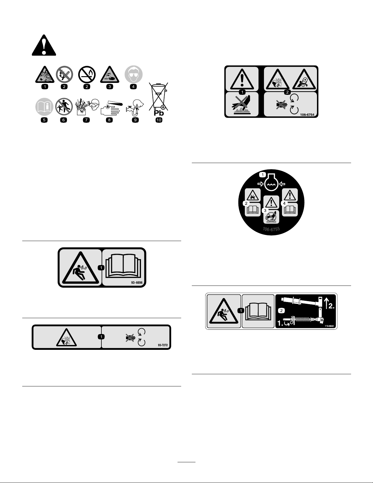
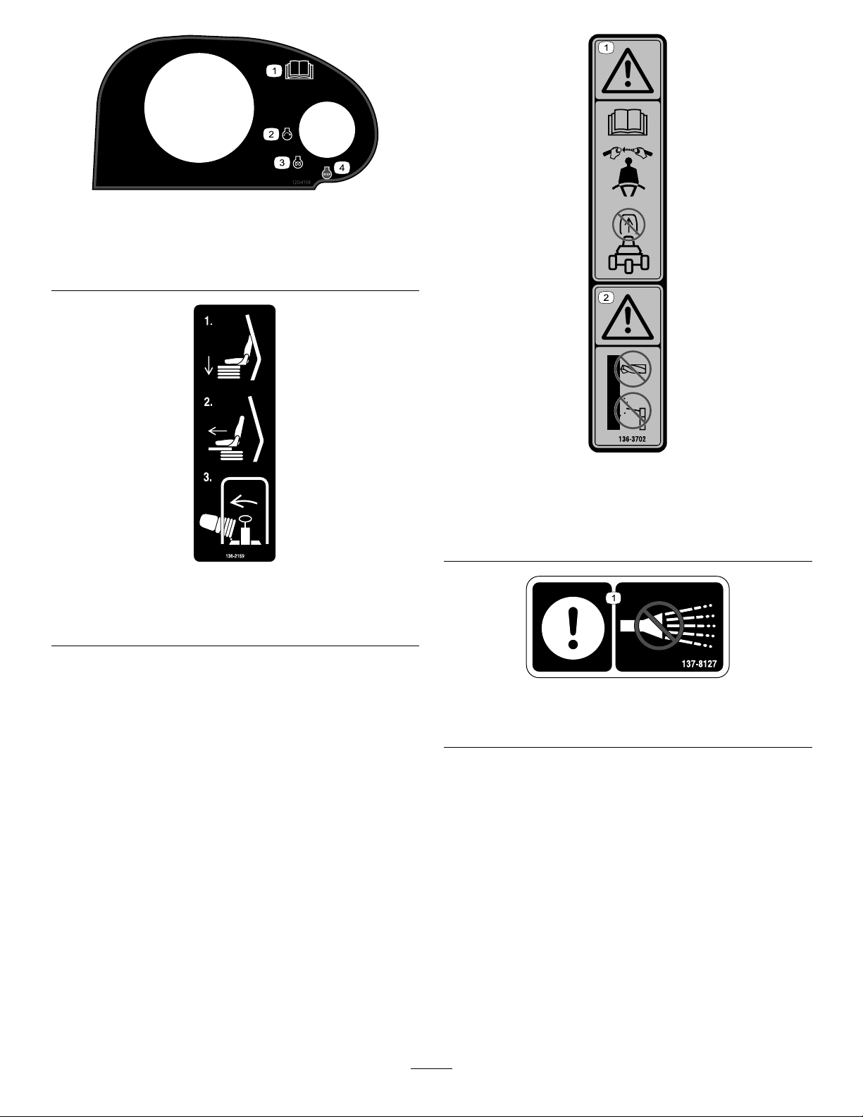
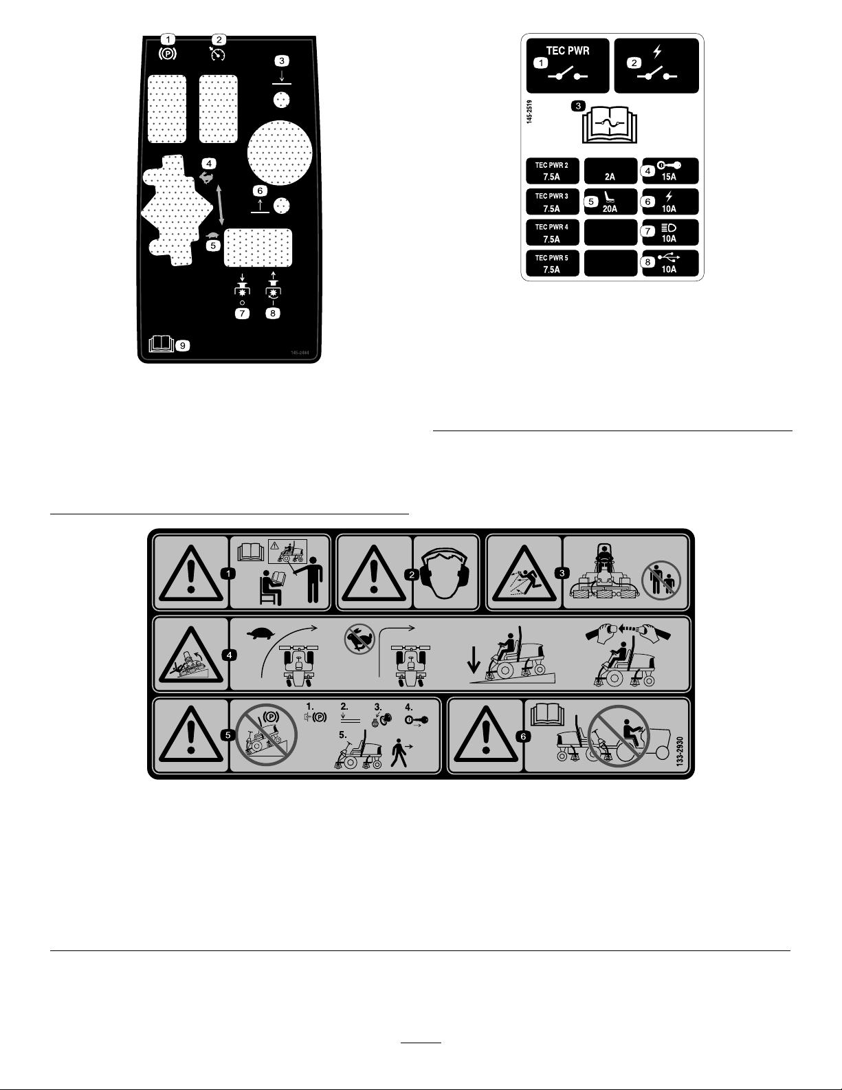
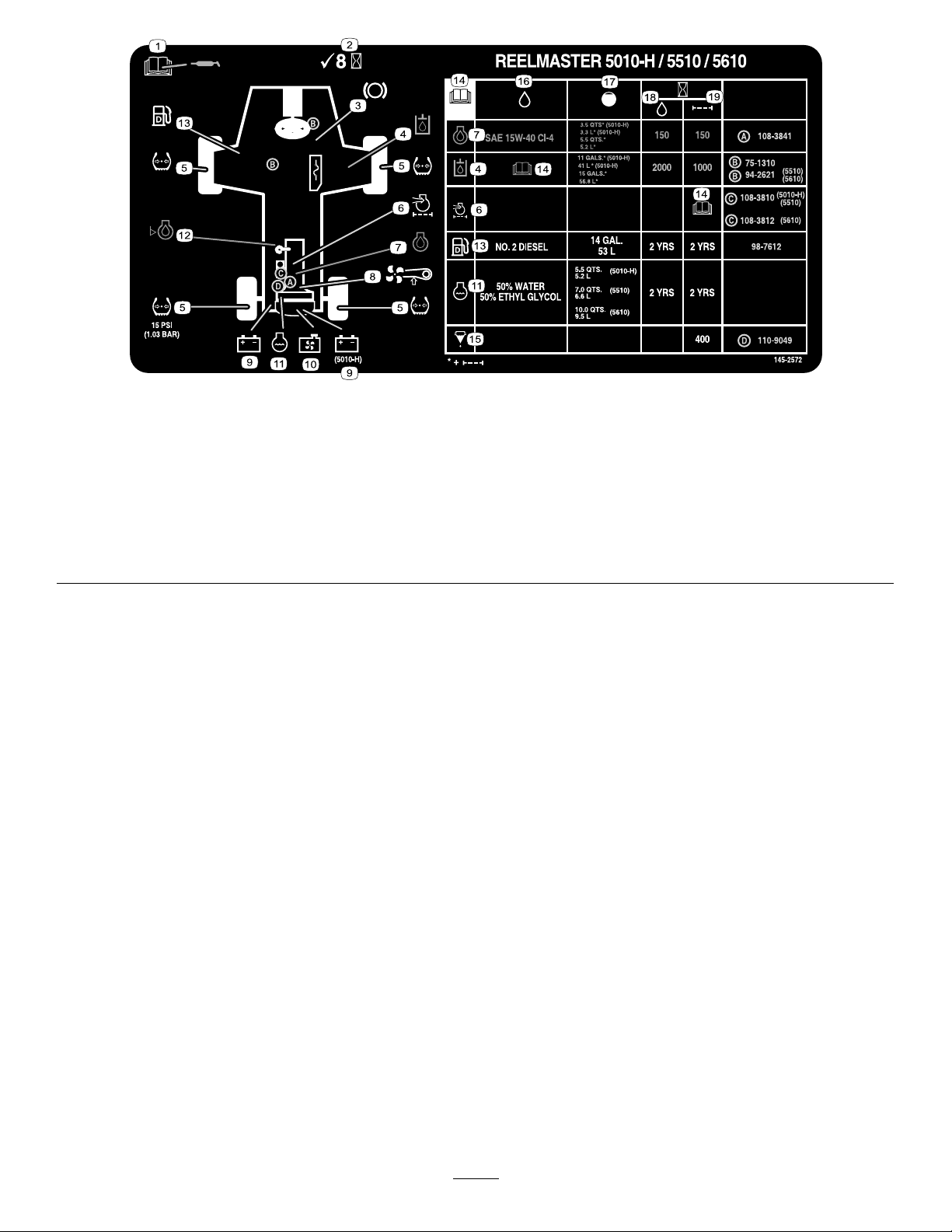
SafetyandInstructionalDecals..........................5
Setup........................................................................9
1PreparingtheMachine.....................................9
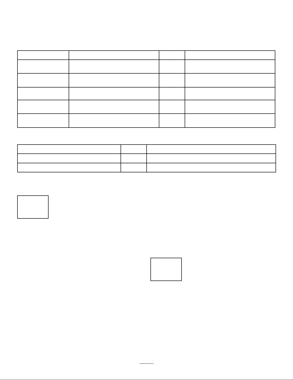
2AdjustingtheControl-ArmPosition...................9
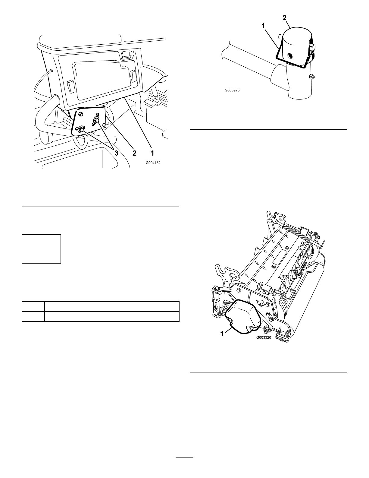
3InstallingtheCuttingUnits..............................10
4UsingtheCutting-UnitKickstand....................17
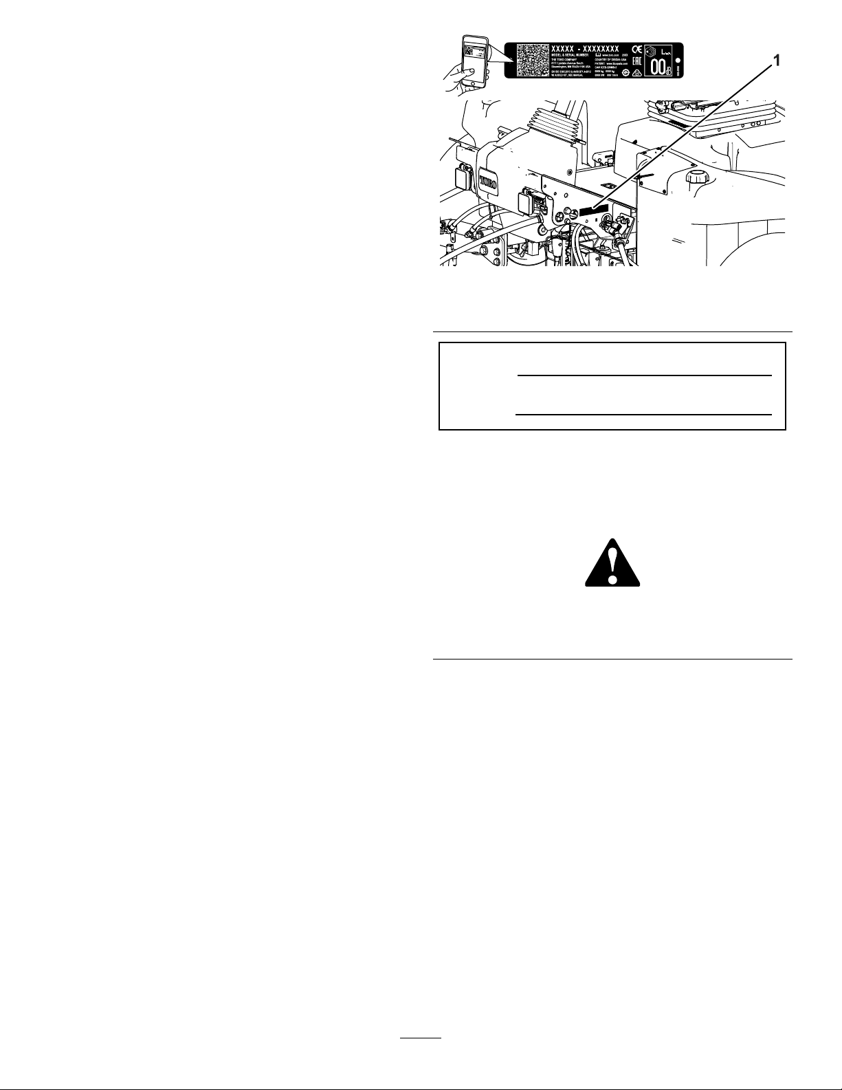
5ApplyingtheProductionYearDecal...............18
ProductOverview...................................................18
Controls...........................................................18
SeatControls................................................20
Specications..................................................21
Attachments/Accessories.................................21
BeforeOperation.................................................22
BeforeOperationSafety...................................22
PerformingDailyMaintenance..........................22
FuelSpecication.............................................22
FuelTankCapacity...........................................23
AddingFuel......................................................23
CheckingtheInterlockSwitches.......................23
UsingtheInfoCenterLCDDisplay....................24
UsingtheMenus...............................................25
ProtectedMenus..............................................26
CheckingtheHydrostaticBraking
Distance........................................................28
UnderstandingDisplayedTraction
Speeds..........................................................29
DuringOperation.................................................29
DuringOperationSafety...................................29
UnderstandingtheOperatingCharacteristics
oftheMachine..............................................30
OperatingtheMachine.....................................30
UsingtheTractionPedal...................................30
UsingtheVirtualPedalStop(VPS)
Feature.........................................................31
OperatingtheCruiseControl............................31
UnderstandingtheAccelerationMode..............32
UnderstandingtheWarm-UpMode...................32
UnderstandingToroSmartPower™.................33
StartingtheEngine...........................................33
ShuttingOfftheEngine.....................................33
CuttingGrasswiththeMachine........................33
SettingtheReelSpeed.....................................34
AdjustingtheLift-ArmCounterbalance.............34
AdjustingtheLift-ArmTurnaround
Position.........................................................35
AdjustingtheTurf-Compensation
Spring...........................................................35
UnderstandingtheDiagnosticLight..................36
OperatingTips.................................................36
AfterOperation....................................................37
AfterOperationSafety......................................37
HaulingtheMachine.........................................37
IdentifyingtheTie-DownPoints........................37
PushingorTowingtheMachine........................38
Maintenance...........................................................40
MaintenanceSafety..........................................40
RecommendedMaintenanceSchedule(s)...........40
DailyMaintenanceChecklist.............................42
Pre-MaintenanceProcedures..............................43
PreparingforMaintenance...............................43
OpeningtheHood............................................43
ClosingtheHood..............................................43
OpeningtheScreen..........................................43
ClosingtheScreen...........................................43
TiltingtheSeat..................................................44
LoweringtheSeat.............................................44
JackingPointLocations....................................44
Lubrication..........................................................45
GreasingtheBearingsandBushings................45
EngineMaintenance...........................................46
EngineSafety...................................................46
CheckingtheAirFilter.......................................46
ServicingtheAirCleaner..................................47
ResettingtheAirFilterServiceIndicator............48
OilSpecication................................................48
CheckingtheLeveloftheEngineOil.................48
CrankcaseOilCapacity....................................48
ChangingtheEngineOilandFilter....................49
FuelSystemMaintenance...................................50
FuelMaintenance.............................................50
StoringFuel......................................................50
ServicingtheFuel-WaterSeparator..................50
BleedingtheFuelSystem.................................51
InspectingtheFuelLinesand
Connections..................................................51
DrainingandCleaningtheFuelTank.................51
CleaningtheFuel-PickupTubeScreen.............52
PrimingtheFuelSystem...................................54
ElectricalSystemMaintenance...........................55
ElectricalSystemSafety...................................55
Disconnectingthe12VBattery.........................55
Connectingthe12VBattery.............................55
Chargingthe12VBattery.................................56
Servicingthe12VBattery.................................56
Replacinga12VFuse-BlockFuse...................56
ReplacingtheTECFuse...................................57
DriveSystemMaintenance..................................58
CheckingtheTireAirPressure..........................58
CheckingtheTorqueoftheWheel
Nuts..............................................................58
CheckingtheRear-WheelAlignment................58
AdjustingtheRearWheelT oe-in.......................58
CoolingSystemMaintenance..............................59
CoolingSystemSafety.....................................59
CoolantSpecication........................................59
CheckingtheCoolantLevel..............................60
RemovingDebrisfromtheCooling
System..........................................................60
BeltMaintenance................................................61
ServicingtheAlternatorBelt.............................61
HydraulicSystemMaintenance...........................62
HydraulicSystemSafety...................................62
3

HydraulicFluidSpecications...........................62
CheckingtheHydraulic-FluidLevel...................62
CheckingtheHydraulicLinesand
Hoses............................................................63
ReplacingtheHydraulicFilters.........................63
HydraulicFluidCapacity...................................64
ChangingtheHydraulicFluid............................64
CuttingUnitMaintenance.....................................66
BladeSafety.....................................................66
CheckingtheReel-to-BedknifeContact............66
BacklappingtheCuttingUnits...........................66
ChassisMaintenance...........................................68
InspectingtheSeatBelt....................................68
ExtendedMaintenance........................................68
ChassisandEngine..........................................68
Cleaning..............................................................69
WashingtheMachine.......................................69
Storage...................................................................69
StorageSafety..................................................69
PreparingtheTractionUnit...............................69
PreparingtheEngine........................................69
StoringtheBattery............................................70
Safety
GeneralSafety
Thisproductiscapableofamputatinghandsandfeet
andofthrowingobjects.
•Readandunderstandthecontentsofthis
Operator’sManualbeforestartingtheengine.
•Useyourfullattentionwhileoperatingthe
machine.Donotengageinanyactivitythat
causesdistractions;otherwise,injuryorproperty
damagemayoccur.
•Donotputyourhandsorfeetnearmoving
componentsofthemachine.
•Donotoperatethemachinewithoutallguards
andothersafetyprotectivedevicesinplaceand
functioningproperlyonthemachine.
•Keepbystandersandchildrenoutoftheoperating
area.Neverallowchildrentooperatethemachine.
•Shutofftheengine,removethekey,andwait
forallmovementtostopbeforeyouleavethe
operator’sposition.Allowthemachinetocool
beforeadjusting,servicing,cleaning,orstoringit.
Improperlyusingormaintainingthismachinecan
resultininjury.Toreducethepotentialforinjury,
complywiththesesafetyinstructionsandalways
payattentiontothesafety-alertsymbol,which
meansCaution,Warning,orDanger—personalsafety
instruction.Failuretocomplywiththeseinstructions
mayresultinpersonalinjuryordeath.
4

SafetyandInstructionalDecals
Safetydecalsandinstructionsareeasilyvisibletotheoperatorandarelocatednearanyarea
ofpotentialdanger.Replaceanydecalthatisdamagedormissing.
decalbatterysymbols
BatterySymbols
Someorallofthesesymbolsareonyourbattery.
1.Explosionhazard6.Keepbystandersaway
fromthebattery.
2.Nore,opename,or
smoking
7.Weareyeprotection;
explosivegasescan
causeblindnessandother
injuries.
3.Causticliquid/chemical
burnhazard
8.Batteryacidcancause
blindnessorsevereburns.
4.Weareyeprotection.9.Flusheyesimmediately
withwaterandgetmedical
helpfast.
5.ReadtheOperator's
Manual.
10.Containslead;donot
discard
decal93-6696
93-6696
1.Storedenergyhazard—readtheOperator'sManual.
decal93-7272
93-7272
1.Cutting/dismembermenthazard;fan—stayawayfrom
movingparts.
decal106-6754
106-6754
1.Warning—donottouchthehotsurface.
2.Cutting/dismembermenthazard,fan;entanglementhazard,
belt—stayawayfrommovingparts.
decal106-6755
106-6755
1.Enginecoolantunder
pressure.
3.Warning—donottouchthe
hotsurface.
2.Explosionhazard—read
theOperator'sManual.
4.Warning—readthe
Operator'sManual.
decal110-9642
110-9642
1.Storedenergyhazard—readtheOperator'sManual.
2.Movethecotterpintotheholeclosesttotherodbracket
andthenremovetheliftarmandpivotyoke.
5

decal120-4158
120-4158
1.ReadtheOperator’s
Manual.
3.Engine—preheat
2.Engine—start4.Engine—stop
decal136-2159
136-2159
1.Moveseatdown3.Rotateseat
2.Slideseatforward
decal136-3702
136-3702
1.Warning—Readthe
Operator’sManual;wear
aseatbelt;donotremove
therollbar.
2.Warning—Donotmodify
therollbar.
decal137-8127
137-8127
1.Attention—donotspraywithhigh-pressurewater.
6

decal145-2484
145-2484
1.Parkingbrake6.Raisethecuttingunits
2.Cruisecontrol7.PTO—Off
3.Lowerthecuttingunits8.PTO—On
4.Fast9.ReadtheOperator’s
Manual.
5.Slow
decal145-2519
145-2519
1.TECpowerrelay5.Air-rideseat
2.Electricalpowerrelay6.Electricalpower
3.ReadtheOperator's
Manualforfuse
information.
7.Headlights
4.Keyswitch8.USBpowerpoint
decal133-2930
133-2930
1.Warning—donotoperatethismachineunlessyouaretrained.4.Tippinghazard—driveslowlywhenturning;donotturnsharply
whiletravelingfast;onlydriveonslopeswiththecuttingunits
lowered;alwayswearaseatbelt.
2.Warning—wearhearingprotection.5.Warning—donotparkonslopes;engagetheparkingbrake,
lowerthecuttingunits,shutofftheengine,andremovethe
ignitionkeybeforeleavingthemachine.
3.Thrownobjecthazard—keepbystandersoutoftheoperating
area.
6.Warning—readtheOperator'sManual;donottowthe
machine.
7

decal145-2572
145-2572
1.ReadtheOperator’s
Manualforlubrication
information.
6.Engineairlter11.Enginecoolant16.Fluids
2.Checkevery8hours.7.Engineoil12.Engineoillevel17.Capacity
3.Brakefunctions8.Fanbelt13.Fuel18.Fluidinterval(hours)
4.Hydraulicuid9.Battery14.ReadtheOperator’s
Manual.
19.Filterinterval(hours)
5.Tirepressure10.Radiatorscreen15.Fuel/Waterseparator
8

Setup
LooseParts
Usethechartbelowtoverifythatallpartshavebeenshipped.
ProcedureDescriptionQty.Use
1Nopartsrequired–Preparethemachine.
2Nopartsrequired–Adjustthecontrol-armposition.
Rightfronthoseguide1
3Leftfronthoseguide1Installthecuttingunits.
4Cutting-unitkickstand1Installthecutting-unitkickstand.
5Productionyeardecal1Applytheproductionyeardecal.
MediaandAdditionalParts
DescriptionQty.Use
Operator'sManual1Readthemanualbeforeoperatingthemachine.
Engineowner’smanual1Readthemanualbeforeoperatingtheengine.
Note:Determinetheleftandrightsidesofthe
machinefromthenormaloperatingposition.
1
PreparingtheMachine
NoPartsRequired
Procedure
1.Parkthemachineonalevelsurface,lowerthe
cuttingunits,andengagetheparkingbrake.
2.Shutofftheengine,removethekey,andwaitfor
allmovingpartstostop.
3.Checkthetireairpressurebeforeuse;referto
CheckingtheTireAirPressure(page58).
Note:Thetiresareoverinatedforshipping.
Adjustthetireairpressurebeforeoperatingthe
machine.
4.Checkthehydraulic-uidlevel;refertoChecking
theHydraulic-FluidLevel(page62).
5.Greasethemachine;refertoGreasingthe
BearingsandBushings(page45).
Important:Failuretoproperlygreasethe
machinewillresultinprematurefailureof
criticalparts.
6.Openthehoodandcheckthecoolantlevel;refer
toCheckingtheCoolantLevel(page60).
7.Checktheleveloftheengine-oillevel,andclose
andlatchthehood;refertoCheckingtheLevel
oftheEngineOil(page48).
Note:Theengineshipswithoilinthe
crankcase;however,checktheoillevelbefore
andaftertheengineisrststarted.
2
AdjustingtheControl-Arm
Position
NoPartsRequired
Procedure
Thecontrol-armpositioncanbeadjustedforyour
comfort.
9

1.Loosenthe2boltssecuringthecontrolarmto
theretainingbracket(Figure3).
g004152
Figure3
1.Controlarm3.Bolts(2)
2.Retainingbrackets
2.Rotatethecontrolarmtothedesiredposition
andtightenthe2bolts.
3
InstallingtheCuttingUnits
Partsneededforthisprocedure:
1Rightfronthoseguide
1Leftfronthoseguide
PreparingtheMachine
1.Removethereelmotorsfromtheshipping
brackets.
2.Removeanddiscardtheshippingbrackets.
3.Ateachcuttingunitliftarm,removethesnapper
pinthatsecuresthecaptotheliftarmpivot
yoke,andremovethecap(Figure4).
g003975
Figure4
1.Snapperpin2.Cap
PreparingtheCuttingUnits
1.Removethecuttingunitsfromthecartons.
2.Assembleandadjustasdescribedinthecutting
unitOperator'sManual.
3.Makesurethatthecounterweight(Figure5)is
installedattheproperendofthecuttingunitas
describedinthecuttingunitOperator'sManual.
g003320
Figure5
1.Counterweight
10

PositioningtheTurfCompensating
SpringandInstallingtheHose
Guide
CuttingUnits4
g375671
Figure6
1.Cuttingunit15.Cuttingunit5
2.Cuttingunit26.Reelmotor
3.Cuttingunit37.Weight
4.Cuttingunit4
1.Ifthehairpinisinstalledintherearholeofthe
compensation-springrod—removethehairpin
andinsertitintheholenexttothebracket
(Figure7).
g375689
Figure7
1.Hairpin
2.Removethe2angelocknuts(3/8inch)and2
carriagebolts(3/8x1-1/4inches)thatsecure
theturf-compensatorbrackettothecutting-unit
frame(Figure8).
g375690
Figure8
1.Carriagebolt(3/8x1-1/4
inches)
3.Flangelocknut(3/8inch)
2.Turf-compensatorbracket
3.Removetheangelocknut(3/8inch)that
securesthecapscrewoftheturfcompensation
springtotherighttabofthecarrierframe,
andremovethecompensationspringfromthe
cuttingunit(Figure9).
Note:Donotremovetheangeserratednut
fromthecapscrew.
g375691
Figure9
1.Capscrew3.Flangelocknut(3/8inch)
2.Righttab(Carrierframe)
4.Assemblethecapscrewoftheturfcompensation
springtotherighttabofthecarrierframe(Figure
10)withtheangelocknut(3/8inch).
11

g375694
Figure10
1.Flangelocknut(3/8inch)3.Capscrew
2.Righttab(Carrierframe)
5.Alignthestudsofthelefthoseguidewith
theholesinthecutting-unitframeandthe
turf-compensatorbracket(Figure11).
Note:Thesupportloopofthehoseguidealigns
towardthecenterlineofthemachine.
g375687
Figure11
1.Turf-compensatorbracket3.Stud(hoseguide)
2.Flangelocknut(3/8inch)4.Inboard
6.Assemblethehoseguideandturf-compensator
brackettothecutting-unitframewiththe2ange
locknuts(3/8inch).
7.Torquethelocknutsandboltsto37to45N∙m
(27to33ft-lb).
InstallingtheHoseGuide
CuttingUnits5
g375672
Figure12
1.Cuttingunit15.Cuttingunit5
2.Cuttingunit26.Reelmotor
3.Cuttingunit37.Weight
4.Cuttingunit4
1.Ifthehairpinisinstalledintherearholeofthe
compensation-springrod—removethehairpin
andinsertitintheholenexttothebracket
(Figure12).
g375689
Figure13
1.Hairpin
2.Removethe2angelocknuts(3/8inch)and2
carriagebolts(3/8x1-1/4inches)thatsecure
theturf-compensatorbrackettothecutting-unit
frame(Figure14).
12

g375690
Figure14
1.Carriagebolt(3/8x1-1/4
inches)
3.Flangelocknut(3/8inch)
2.Turf-compensatorbracket
3.Alignthestudsoftherighthoseguidewith
theholesinthecutting-unitframeandthe
turf-compensatorbracket(Figure15).
Note:Ensurethatthesupportloopofthe
hoseguidealignstowardthecenterlineofthe
machine.
g375688
Figure15
1.Stud(hoseguide)3.Flangelocknut(3/8inch)
2.Turf-compensatorbracket4.Inboard
4.Assemblethehoseguideandturf-compensator
brackettothecutting-unitframewiththe2ange
locknuts(3/8inch).
5.Torquethelocknutsto37to45N∙m(27to33
ft-lb).
PositioningtheTurfCompensating
Spring
CuttingUnit2
g379514
Figure16
1.Cuttingunit15.Cuttingunit5
2.Cuttingunit26.Reelmotor
3.Cuttingunit37.Weight
4.Cuttingunit4
1.Ifthehairpinisinstalledintherearholeofthe
compensation-springrod—removethehairpin
andinsertitintheholenexttothebracket
(Figure17).
g375689
Figure17
1.Hairpin
2.Removethe2angelocknuts(3/8inch)and2
carriagebolts(3/8x1-1/4inches)thatsecure
theturf-compensatorbrackettothecutting-unit
frame(Figure18).
13

g375690
Figure18
1.Carriagebolt(3/8x1-1/4
inches)
3.Flangelocknut(3/8inch)
2.Turf-compensatorbracket
3.Removetheangelocknut(3/8inch)that
securesthecapscrewoftheturfcompensation
springtotherighttabofthecarrierframe,
andremovethecompensationspringfromthe
cuttingunit(Figure19).
Note:Donotremovetheangeserratednut
fromthecapscrew.
g375691
Figure19
1.Capscrew3.Flangelocknut(3/8inch)
2.Righttab(Carrierframe)
4.Assemblethecapscrewoftheturfcompensation
springtotherighttabofthecarrierframe(Figure
20)withtheangelocknut(3/8inch).
g375694
Figure20
1.Flangelocknut(3/8inch)3.Capscrew
2.Righttab(Carrierframe)
5.Aligntheholesintheturf-compensatorbracket
withtheholesinthecutting-unitframe(Figure
21).
Note:Thesupportloopofthehoseguidealigns
towardthecenterlineofthemachine.
g378789
Figure21
1.Turf-compensatorbracket3.Flangelocknut(3/8inch)
2.Carriagebolt(3/8x1-1/4
inches)
4.Inboard
6.Assembletheturf-compensatorbrackettothe
cutting-unitframewiththe2carriagebolts(3/8x
1-1/4inches)and2angelocknuts(3/8inch).
7.Torquethelocknutsandboltsto37to45N∙m
(27to33ft-lb).
InstallingtheKickstand
Foreachcuttingunit,securethekickstandtothe
chainbracketwiththesnapperpin(Figure22).
14

g004144
Figure22
1.Chainbracket3.Cutting-unitkickstand
2.Snapperpin
InstallingtheFrontCuttingUnits
totheLiftArms
1.Slideacuttingunitundertheliftarm(Figure23).
g375274
Figure23
1.Cap3.Pivotyoke
2.Snapperpin4.Carrierframeshaft
2.Assemblethepivotyokeontothecarrierframe
shaft.
3.Assemblethecaptothepivotyoke,andalign
theholesinthecarrierframeshaft,pivotyoke,
andcap.
4.Securethecapandthecarrier-frameshaftto
thepivotyokewiththesnapperpin.
5.Lockthecutting-unitpivotforcuttinggrassona
hillside;refertoLockingtheCutting-UnitPivot
forCuttingGrassonaHillSide(page16).
InstallingtheRearCuttingUnitsto
theLiftArms
CuttingUnitsadjustedfora1.2cm(3/4inch)
orHigherHeightofCut
1.Slideacuttingunitundertheliftarm(Figure24).
g375252
Figure24
1.Cap3.Pivotyoke
2.Snapperpin4.Carrierframeshaft
2.Assemblethepivotyokeontothecarrierframe
shaft.
3.Assemblethecaptothepivotyokeandalign
theholesinthecarrierframeshaft,pivotyoke,
andcap.
4.Securethepivotarmshaftandcaptothecarrier
frameshaftwiththesnapperpin.
5.Lockthecutting-unitpivotforcuttinggrassona
hillside;refertoLockingtheCutting-UnitPivot
forCuttingGrassonaHillSide(page16).
6.Repeatsteps1and2fortheotherrearcutting
unit.
InstallingtheRearCuttingUnitsto
theLiftArms
CuttingUnitsadjustedfora1.2cm(3/4inch)
orLowerHeightofCut
1.Removethelynchpinandwashersecuringthe
pivotyoketotheliftarmandslidetheshaftout
oftheliftarm(Figure25).
15

g375236
Figure25
1.Lynchpin3.Liftarm(rearcuttingunit)
2.Pivotyoke4.Washer
2.Assemblethepivotyokeontothecarrierframe
shaft(Figure26).
g375237
Figure26
1.Cap3.Pivotyoke
2.Snapperpin4.Carrierframeshaft
3.Assemblethecaptothepivotyoke,andalign
theholesinthecarrierframeshaft,pivotyoke,
andcap.
4.Securethepivotyokeandcaptothecarrier
frameshaftwiththesnapperpin.
5.Lockthecutting-unitpivotforcuttinggrassona
hillside;refertoLockingtheCutting-UnitPivot
forCuttingGrassonaHillSide(page16).
6.Slideacuttingunitundertheliftarm(Figure27).
g375239
Figure27
1.Lynchpin3.Liftarm
2.Lift-armshaft4.Washer
7.Insertthepivotyokeintotheliftarm,andsecure
shafttothearmwiththelynchpinandwasher.
8.Repeatsteps1through7fortheotherrear
cuttingunit.
LockingtheCutting-UnitPivotfor
CuttingGrassonaHillSide
Lockthecutting-unitpivotstopreventthecuttingunits
fromrotatingdownhillwhencuttingacrossthefaceof
ahill.Usetheholeinthepivotyoke(Figure28)lock
thecuttingunit.Usetheslotforasteeringcuttingunit.
g375251
Figure28
1.Snapper-pinpositions3.Slot(pivotyoke)
2.Hole(pivotyoke)
InstallingtheCuttingUnitLift-Arm
Chains
Securethelift-armchaintothechainbracketwiththe
snapperpin(Figure29).
Note:Usethenumberofchainlinksdescribedinthe
cuttingunitOperator'sManual.
16

g003948
Figure29
1.Lift-armchain3.Snapperpin
2.Chainbracket
InstallingtheReelMotors
1.Coatthesplineshaftofthereelmotorwithclean
grease.
2.OilthereelmotorO-ringandinstallitontothe
motorange.
3.Installthemotorbyrotatingitclockwisesothat
themotorangesclearthebolts(Figure30).
g004127
Figure30
1.Reel-drivemotor2.Mountingbolts
4.Rotatethemotorcounterclockwiseuntilthe
angesencirclethebolts,andthentightenthe
bolts.
Important:Makesurethatthereelmotor
hosesarenottwisted,kinked,oratriskof
beingpinched.
5.Torquethemountingboltsto(27to33ft-lb).
4
UsingtheCutting-Unit
Kickstand
Partsneededforthisprocedure:
1Cutting-unitkickstand
Procedure
Wheneveryoumusttipthecuttingunittoexposethe
bedknife/reel,propuptherearofthecuttingunitwith
thekickstandtoensurethatthenutsonthebackend
ofthebedbaradjustingscrewsarenotrestingonthe
worksurface(Figure31).
g003985
Figure31
1.Cutting-unitkickstand
Securethekickstandtothechainbracketwiththe
snapperpin(Figure32).
17

g004144
Figure32
5
ApplyingtheProduction
YearDecal
Partsneededforthisprocedure:
1Productionyeardecal
Procedure
1.Userubbingalcoholandacleanragtocleanthe
oorbracketareanexttotheserialplate,and
allowthebrackettodry(Figure33).
g375339
Figure33
1.Yearofproductiondecal2.Serialplate
2.Removethebackingfromtheyearofproduction
decal.
3.Applythedecaltotheoorbracket.
ProductOverview
g216864
Figure34
1.Enginehood5.Seatadjustments
2.Seat6.Frontcuttingunits
3.Controlarm7.Rearcuttingunits
4.Steeringwheel
Controls
g422390
Figure35
1.Keyswitch5.Throttlelever
2.Cruisecontrol6.Headlightswitch
3.Lowermow/raisecontrol
lever
7.Parking-brakeswitch
4.PTOswitch8.InfoCenter
18

g383839
Figure36
1.Tractionpedal2.Tiltsteeringpedal
ThrottleControl
Movethethrottle-controllever(Figure34)forwardto
increasetheenginespeedandrearwardtodecrease
speed.
TractionPedal
Thetractionpedal(Figure36)controlstheforwardand
reverseoperation.Pressthetopofthepedaltomove
forwardandthebottomtomoverearward.Ground
speeddependsonhowfaryoupressthepedal.For
noload,maximumgroundspeed,fullypressthepedal
whilethethrottleisintheFASTposition.
Tostop,reducefootpressureonthetractionpedal
andallowittoreturntothecenterposition.
Cruise-ControlSwitch
Thecruise-controlswitchhas3positions:OFF,ON,
andENGAGE.
Toturnonthecruisecontrol,pivottheswitchtothe
middleposition.
Toengagethecruisecontrol,brieypivottheswitch
forward.Whencruisecontrolisengaged,thecruise
controlscreenwillappearontheInfoCenter.Usethe
InfoCenterbuttonstoadjustthecruisecontrolspeed
in0.8km/h(0.5mph)increments.
Tilt-SteeringPedal
Totiltthesteeringwheeltowardyou,pressthefoot
pedal(Figure36)down,andpullthesteeringtower
towardyoutothemostcomfortablepositionandthen
releasethepedal.
KeySwitch
Thekeyswitch(Figure35)has3positions:OFF,
ON/PREHEAT,andSTART.
Power-takeoff(PTO)Switch
WhenthePTOswitchisengaged,themachineisin
MOWmode,whichallowsyoutodriveupto13km/h
(8mph)whenthemaximumspeedisnotlimited.
WhenthePTOswitchisnotengaged(Figure37),the
machineisinTRANSPORTmode,whichallowsyou
todriveupto16km/h(10mph)whenthemaximum
speedisnotlimited.
Note:UsetheprotectedmenusintheInfoCenterto
setthemaximumspeedforeachmode.
g424477
Figure37
1.Disengaged2.Engaged
ParkingBrake
Toengagetheparkingbrake,(Figure35)pivotthe
switchforwardontheconsole.Theredlightonthe
switchturnsonwhenitisset.Toreleasetheparking
brake,pivottheswitchbackward.
Activatingtheparking-brakeswitchcausesthetraction
toautomaticallydecelerate,regardlessoftraction
pedalposition,andengagetheparkingbrakeassoon
asthemachinecomestoastop.
Oncetheenginehasbeenshutoffandthemachineis
notmoving,theparkingbrakeengages,regardlessof
parking-brakeswitchposition.
LowerMow/RaiseControlLever
Thislever(Figure35)raisesandlowersthecutting
units.
Tolowerthecuttingunits,pushtheleverforward.
WhenthePTOisengagedandthecuttingunitsare
lowered,thecuttingunitsstartspinning.Ifthecutting
unitsareloweredbeforethePTOisengaged,the
cuttingunitswillnotstartspinning.
InfoCenter
TheInfoCenterLCDdisplayshowsinformationabout
yourmachine,suchastheoperatingstatus,various
19

diagnostics,andotherinformationaboutthemachine
(Figure35).
Thescreensthatdisplay,dependonwhichbuttons
youselect.Thepurposeofeachbuttonmaychange
dependingonwhatisrequiredatthetime.
HeadlightSwitch
Pivottheswitchupwardtoturnontheheadlights
(Figure35).
Hydraulic-Filter-Restriction
Indicator
Thehydraulic-lter-restrictionindicatoralertsyou
whenthehydraulicltersmustbechanged;referto
ReplacingtheHydraulicFilters(page63).
g031683
Figure38
1.Hydraulic-lter-restrictionindicator
PowerPoint
Thepowerpoint(Figure39)isa12Vpowersupply
forelectronicdevices.
g419730
Figure39
1.Powerpoint
BacklapLevers
Usethebacklapleversinconjunctionwiththelower
mow/raisecontrolleverforbacklappingthereels
(Figure40).
g021209
Figure40
1.Backlaplevers
SeatControls
g419753
Figure41
1.Weightgauge3.Height-adjustingknob
2.Weight-adjustingknob4.Seat-positionlever
Weight-AdjustingKnob
Rotatetheweight-adjustingknobuntilyourweightis
displayedinthewindowoftheweightgauge.
Height-AdjustingKnob
Rotatetheheight-adjustingknobtochangetheheight
oftheseat.
20
This manual suits for next models
1
Table of contents
Other Toro Lawn Mower manuals

Toro
Toro 30092 User manual

Toro
Toro Super Recycler 20381 User manual

Toro
Toro Z Master Z500 Series Manual

Toro
Toro 16401 User manual

Toro
Toro 72201 User manual

Toro
Toro 30434 User manual

Toro
Toro 74480 User manual

Toro
Toro Z Master Professional 7000 Series User manual

Toro
Toro Z Master Commercial 2000 Series User manual

Toro
Toro 30318 User manual