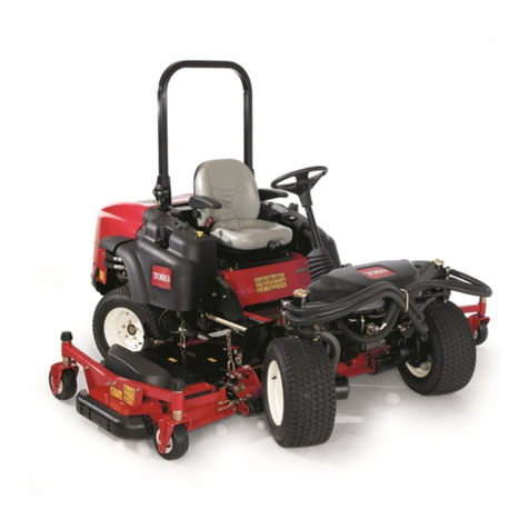
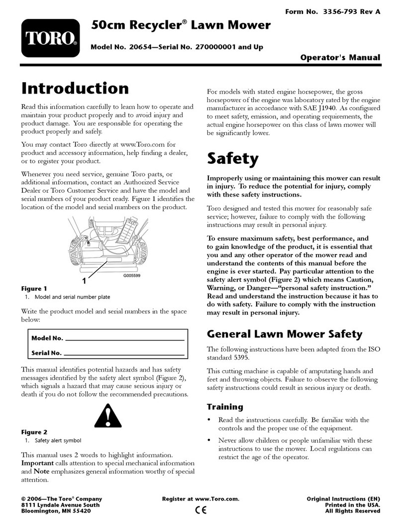
Toro 30200 User manual

%5
(%
(% #/.&/1-2 3/ 3(%
-%1)#!. !3)/.!, 3!.$!1$2 .23)343%2 2!&%38
23!.$!1$2 &/1 1)$).' -/6%12 6(%. 6%)'(32 !1%
).23!,,%$ !##/1$).' 3/ #(!13 /. 0!'% 3(42
01/4$,8 $)20,!82 3(% 2!&%38 2%!,
/ !2241% -!7)-4- 2!&%38 /03)-4- 0%1&/1-!.#%
!.$ 3/ '!). +./6,%$'% /& 3(% 01/$4#3 )3 )2 %22%.3)!,
3(!3 8/4 /1 !.8 /3(%1 /0%1!3/1 /& 3(% -/6%1 1%!$
!.$ 4.$%123!.$ 3(% #/.3%.32 /& 3()2 -!.4!, "%&/1%
3(% %.').% )2 %5%1 23!13%$ !8 0!13)#4,!1 !33%.3)/.
3/ 3(% ()'(,)'(3%$ "8 3()2
28-"/, 9
(% 2!&%38 !,%13 28-"/, -%!.2
/1 0%12/.!, 2!&%38
).2314#3)/. !),41% 3/ #/-0,8 6)3( 3(% ).2314#3)/.
-!8 1%24,3 ). 0%12/.!, ).*418

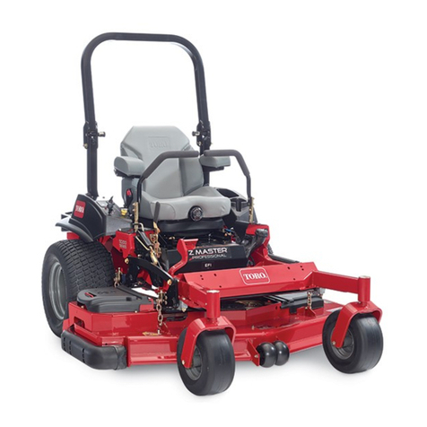
The GROUND MA TER 1000L was developed to satisfy the demand for a maneuverable, intermediate size, turf
maintenance rotary mower. The machine has advanced concepts in engineering, design and safety; and if
maintained properly, it will give excellent service.
ince the GROUND MA TER 1000L is a high quality product, Toro is concerned about the future use of the
machine and the safety of the user. Read this manual to familiarize yourself with the proper set up, operation, and
maintenance instructions. The major sections of this manual are:
"$ !" #"!
" !" #"!
"
" !" #"!
"
Certain information in this manual is emphasized. DANGER, WARNING and CAUTION identify personal safety
related information. IMPORTANT identifies mechanical information demanding special attention. Be sure to read
the directive because it deals with the possibility of damaging a part or parts of the machine. NOTE identifies general
information worthy of special attention.
If help concerning set up, operation, maintenance or safety is ever needed, contact a local Authorized Toro Dealer. In
addition to genuine Toro replacement parts, the dealer also has optional equipment form the complete line of Toro
turf care equipment. Keep your Toro all Toro Ċ buy genuine Toro replacement parts and accessories.
The engine exhaust from this product
contains chemicals known to the State of
California to cause cancer, birth defects,
or other reproductive harm.
Because in some areas there are local, state or federal regulations requiring that a spark arrestor muffler be used on
the engine of this mower, a spark arrestor screen is available as an option. If a spark arrestor muffler is required,
order the following part from you Authorized Toro Dealer.
(1)75-6880 park Arrestor creen
This part is certified to meet the requirements of U DA Forest ervice tandard No. 5100-1A.
When the mower is used or operated on any California forest, brush or grass covered land, a properly operating
spark arrester must be attached to the muffler. The operator is violating state law, ection 442 Public Resources
Code if a spark arrester is not used.
Whenever you have questions or need service, contact your local authorized Toro Dealer. In addition to having a
complete line of accessories and professional turf care service technicians, the dealer has a complete line of
genuine TORO replacement parts to keep your machine operating properly. Keep your TORO all TORO. Buy
genuine TORO parts and accessories.

#
#
Check Engine Oil 12. . . . . . . . . . . . . . . . . . . . . . . . .
Check Cooling System 12. . . . . . . . . . . . . . . . . . . .
Check Hy raulic System Flui 13. . . . . . . . . . . . .
Fill Fuel Tank 14. . . . . . . . . . . . . . . . . . . . . . . . . . . . .
Starting an Stopping 17. . . . . . . . . . . . . . . . . . . . .
Checking Interlock System 17. . . . . . . . . . . . . . . .
Operating Characteristics 17. . . . . . . . . . . . . . . . . .
Pushing Or Towing Traction Unit 18. . . . . . . . . . . .
Greasing Bearings An Bushings 19. . . . . . . . . . .
! !
#
Air Cleaner Maintenance 23. . . . . . . . . . . . . . . . . .
Cleaning Ra iator, Oil Cooler An Screen 23. . .
Changing Engine Oil An Filter 23. . . . . . . . . . . . .
Servicing Fuel System 24. . . . . . . . . . . . . . . . . . . . .
Checking an Replacing Spark Plugs 24. . . . . . .
Servicing PTO Belt 25. . . . . . . . . . . . . . . . . . . . . . . .
PTO Clutch A justment 25. . . . . . . . . . . . . . . . . . .
Changing Coolant In Cooling System 25. . . . . . .
A justing Transmission For Neutral 26. . . . . . . . .
Changing Transmission Filter 26. . . . . . . . . . . . . .
A justing Service Brakes 27. . . . . . . . . . . . . . . . . .
Servicing Battery 27. . . . . . . . . . . . . . . . . . . . . . . . .
Wiring Harness Service 27. . . . . . . . . . . . . . . . . . . .
Fuses 27. . . . . . . . . . . . . . . . . . . . . . . . . . . . . . . . . . .
#
"# $%' (*&)

!
)& 6"2 3&23&% ".%
$&13*'*&% #7 '/1 $/-0,*".$& 6*3) 3)&
9 20&$*'*$"3*/.2 /' 3)& -&1*$". "3*/.",
3".%"1%2 .23*343& ,3)/4() )"8"1% $/.31/, ".%
"$$*%&.3 01&5&.3*/. 0"13*",,7 "1& %&0&.%&.3 40/.
3)& %&2*(. ".% $/.'*(41"3*/. /' 3)& -"$)*.& 3)&2&
'"$3/12 "1& ",2/ %&0&.%&.3 40/. 3)& "6"1&.&22
$/.$&1. ".% 01/0&1 31"*.*.( /' 3)& 0&12/..&,
*.5/,5&% *. 3)& /0&1"3*/. 31".20/13 -"*.3&.".$&
".% 23/1"(& /' 3)& -"$)*.& -01/0&1 42& /1
-"*.3&.".$& /' 3)& -"$)*.& $". 1&24,3 *. *.+417 /1
%&"3) / 1&%4$& 3)& 0/3&.3*", '/1 *.+417 /1 %&"3)
$/-0,7 6*3) 3)& '/,,/6*.( 2"'&37 *.2314$3*/.2
ead and understand the contents of this manual
before starting and operating the machine. Become
familiar with the controls and know how to stop the
machine and engine quickly. A free replacement
manual is available by sending the complete model
and serial number to:
The Toro Company
8111 Lyndale Avenue South
Minneapolis, Minnesota 55420-1196.
Never allow children to operate the machine. Do
not allow adults to operate machine without proper
instruction. Only trained operators who have read this
manual should operate this machine.
Never operate the machine when under the
influence of drugs or alcohol.
emove all debris or other objects that might be
picked up and thrown by the blades or fast moving
components from other attached implements. Keep all
bystanders away from operating area.
Keep all shields, safety devices and decals in
place. If a shield, safety device or decal is defective,
illegible or damaged, repair or replace it before
operating the machine. Also tighten any loose nuts,
bolts or screws to ensure machine is in safe operating
condition.
Always wear substantial shoes. Do not operate
machine while wearing sandals, tennis shoes,
sneakers or when barefoot. Do not wear loose fitting
clothing that could get caught in moving parts and
possibly cause personal injury. Wearing safety
glasses, safety shoes, long pants and a helmet is
advisable and required by some local ordinances and
insurance regulations.
Check interlock switches daily for proper operation
( efer To Checking Interlock Switches, Page 17). Do
not rely entirely on safety switches Ćshut off engine
before getting off seat. If a switch fails, replace it before
operating the machine. The interlock system is for your
protection, so do not bypass it. eplace all interlock
switches every two years. Interlock switches should be
adjusted so:
A. Engine cannot be started unless traction pedal
is released (neutral position)Ċand PTO lever is
DISENGAGED (off position).
B. Engine stops if operator gets off seat when
traction pedal is depressed.
C. Engine stops if operator gets off seat when
PTO lever is ENGAGED (on position).
Grass deflectors must be installed in lowest
position on side discharge units.
Since gasoline is highly flammable, handle it
carefully:
A. Use an approved fuel container.
B. Do not remove fuel tank cap while engine is hot
or running.
C. Do not smoke while handling fuel.
D. Fill fuel tank outdoors and only to within an
inch from the top of the tank, not the filler neck. Do
not overfill.
E. Wipe up any spilled fuel.
Sit on the seat when starting and operating the
machine.
Before starting the engine:
A. Engage the parking brake.
B. Make sure traction pedal is in NEUT AL and
PTO switch in OFF position.
C. After engine is started, release parking brake
and keep foot off traction pedal. Machine must not
move. If movement is evident, the neutral return
mechanism is adjusted incorrectly; therefore, shut
engine off and adjust until machine does not move
when traction pedal is released.
Seating capacity is one person. Therefore, never
carry passengers.
Do not run engine in a confined area without
adequate ventilation. Exhaust fumes are hazardous
and could possibly be deadly.
Traverse slopes carefully. Do not start or stop
suddenly when traveling uphill or downhill.
Operator must be skilled and trained in how to
drive on hillsides. Failure to use caution on slopes or
hills may cause loss of control and vehicle to tip or roll
possibly resulting in personal injury or death.
!
This produ t may ex eed noise levels of 85 dB(A)
at the operator position. Ear prote tors are
re ommended for prolonged exposure to redu e the
potential of permanent hearing damage.
Using the ma hine demands attention and to
prevent loss of ontrol:
A. Operate only in daylight or when there is good
artifi ial light.
B. Drive slowly. Avoid sudden stops and starts.
C. Wat h for holes or other hidden hazards.
D. Look behind ma hine before ba king up.
E. Do not drive lose to a sand trap, dit h, reek
or other hazard.
F. Redu e speed when making sharp turns and
turning on a hillside.
G. The utting de k must be lowered when going
down slopes for steering ontrol.
If engine stalls or loses headway and annot make
it to the top of a slope, do not turn ma hine around.
Always ba k slowly straight down the slope.
Never raise the utting unit or other atta hed
implement while the blades or other parts are rotating.
The grass defle tor must always be installed and in
the lowest position on the utting unit. This produ t is
designed to drive obje ts into the ground where they
lose energy qui kly in grassy areas.
! When a person or pet appears
unexpe tedly in or near the mowing area,
. Careless operation, ombined with terrain
angles, ri o hets, or improperly positioned guards an
lead to thrown obje t injuries. Do not resume mowing
until area is leared.
Do not tou h engine, muffler or exhaust pipe while
engine is running or soon after it is stopped. These
areas ould be hot enough to ause burns.
If utting de k strikes a solid obje t or vibrates
abnormally, stop immediately, turn engine off, set
parking brake and wait for all motion to stop. Inspe t
for damage. If damaged, repair or repla e any
omponents before operating.
Before getting off the seat:
A. Move tra tion pedal to neutral position and
remove foot from pedal.
B. Set the parking brake and turn the PTO swit h
OFF.
C. Shut the engine OFF and remove key from
ignition swit h. Wait for all ma hine movement to
stop before getting off the seat.
Before servi ing or making adjustments, stop
engine and remove key from the swit h.
Make sure ma hine is in safe operating ondition
by keeping all nuts, bolts and s rews tight.
Make sure all hydrauli line onne tors are tight,
and all hydrauli hoses and lines are in good ondition
before applying pressure to the system.
Keep body and hands away from pin hole leaks or
nozzles that eje t high pressure hydrauli fluid. Use
ardboard or paper to find hydrauli leaks. Hydrauli
fluid es aping under pressure an penetrate skin and
ause injury. Fluid a identally inje ted into the skin
must be surgi ally removed within a few hours by a
do tor familiar with this form of injury or gangrene may
result.
Before dis onne ting or performing any work on
the hydrauli system, all pressure in system must be
relieved by stopping engine and lowering implement
to the ground.
If major repairs are ever needed or assistan e is
desired, onta t an Authorized Toro Dealer.
To redu e potential fire hazard, keep engine area
free of ex essive grease, grass, leaves and dirt.
If engine must be running to perform maintenan e
or an adjustment, keep hands, feet, lothing and other
parts of the body away from utting de k and other
moving parts. Keep all bystanders away.
Do not overspeed the engine by hanging
governor setting. To assure safety and a ura y, have
an Authorized Toro Dealer he k maximum engine
speed.
Shut engine off before he king or adding oil to the
rank ase.
At the time of manufa ture, the ma hine
onformed to the safety standards for riding mowers
when weights are installed a ording to hart on page
11. To assure optimum performan e and ontinued
safety ertifi ation of the ma hine, use genuine Toro
repla ement parts and a essories. Repla ement
parts and a essories made by other manufa turers
may result in nonĆ onforman e with the safety
standards, and the warranty may be voided.

!& !"!
The following safety and instruction decals are affixed to the traction unit. If any decal becomes illegible or damaged,
install a new decal. Part numbers are listed below and in your Parts Catalog.
"
'01 /
! # $
'01 /
! ! !
'01 /
! ! $!
'01 / ! "
'01 /
! !
'01 /
! !
'01 /
"
'01 /
! %
'01 /
! % #
'01 /
! %
'01 /
!!
. 2**-)0 +,)-(
'01 /

7
S ECIFICATIONS
Engine:
Manufacturer Ċ Kawasaki
Horsepower Ċ 20 @ 3600 RPM.
Displacement Ċ 617 cc.
Crankcase Capacity Ċ 1.6 qts. w/filter.
Governor Ċ Mechanical.
Governor Limit Ċ 3350Ć3550 RPM.
dle Speed Ċ 1500 RPM.
Air Cleaner: Kawasaki duel element filter.
Fuel Tank Capacity: 8.5 gal.
Fuel Filter: Replaceable inline type.
Fuel ump: 12 volt electric (transistor type).
Cooling System:
Radiator Ċ Approx.4 qt. capacity.
Expansion Tank Ċ Remote mounted; 1/2 qt.
capacity. System contains a 50/50 mix of ethylene
glycol antiĆfreeze and water.
Electrical: Battery Ċ 12 volt, BC group size 26. 530
Amp at 0 F. 20 amp alternator with regulator/rectifier.
Drive Coupling: Transmission driven by steel shaft
with flexible rubber couplings at each end.
Transmission;
Manufacturer & Type Ċ Sundstrand hydrostatic,
Type U15.
Normal Charge Pressure Ċ 70Ć150 psi
(483Ć1034 kPa).
mplement Relief Setting Ċ 700Ć800 psi
(4 826 Ć 5 516 kPa).
Hydraulic Filter: 25 micron mounted directly to
transmission. Replaceable (Toro Part No. 23-2300).
Drive Axle: Manufacturer Ċ Dana Corp., Model GTĆ20.
Axle serves as a hydraulic fluid reservoir and mates
directly with the transmission. Approximately 5 qt.
capacity.
Brakes: Mechanical drum type, 7 in. dia. x 1Ć3/4 in.
wide. ndividually controlled by two pedals connected
by cable and conduit for steering assist. Pedals may be
latched together for two wheel braking. Lever provided
for parking brake.
Tires, Wheels, ressure:
Front Tires Ċ 23 x 8.50 - 12
Rear Tires Ċ 16 x 6.50 - 8
All tires 4 ply rating, tubeless type.
Pressure Ċ 20 psi.
Steering: 13 in. steering wheel. TRW power steering
valve.
Main Frame: Frame is welded, formed steel.
Seat: Adjustable contoured fit with suspension lever.
Instrumentation: Fuel gauge, water temperature
gauge, hour meter and warning lights for high
temperature shutdown, oil pressure and amperage are
mounted on the console.
Controls: Throttle, choke, PTO switch, parking brake,
implement lift and ignition switch are all
handĆoperated. Forward/reverse traction pedal and
turning brakes are foot operated.
TO Drive: Splined PTO shaft is clutched by a
torqueĆteamed HA Section, spring tensioned VĆbelt
directly from engine output shaft. PTO shaft engaged
by electric clutch/brake assembly. PTO speed Ċ 2200
RPM @ 3450 RPM engine speed.
Implement Connection Ċ Universal joint and
telescoping shaft assembly.
Lift Cylinders: Two, with 2 in. bore, 3.5 in. stroke.
Interlock Switches: Prevents engine starting if traction
pedal or PTO switch are engaged. Stops engine if
operator leaves seat with either traction pedal or PTO
switch engaged.
Dimensions and Weight (approx.):
Traction Unit w/Standard Seat
Length: 82 in.
Width: (Rear Wheels) 44 in.
Height: 50 in.
Weight: 1116 lb
O TIONAL EQUI MENT
52" Side Discharge Cutting UnitĊModel No. 30555
52" Rear Discharge Cutting UnitĊModel No. 30568
62" Side Discharge Cutting UnitĊModel No. 30564
62" Guardian Recycler Cutting UnitĊModel No.
30569
72" Side Discharge Cutting UnitĊModel No. 30575
48" VĆ low Kit Ċ Model No. 30750
VĆ low Mounting Kit Ċ Model No. 30749. Required
with 30750 VĆPlow. 11Ć0390 Tire Chains
recommended.
Arm Rest Kit Ċ Part No. 88-3230
Rear Discharge Shield Kit Ċ Model No. 30567.
Rear Weight Box Kit Ċ Part No. 24-5780.
Grass Collection System Ċ Model No. 30502, 52"
Blower Kit (for Model 30555 deck) or Model 30503 62"
Blower Kit (for Model 30564 deck) can be used with
either Model No. 30504, 9 cu. fit. Hopper Kit or Model
No. 30505, 15 cu. ft. Hopper Kit.
Wide Tires w/rim: 23 x 10.5 Ć 12 Ċ Part No. 62-7020.
Wheel Weights: Ċ Part No. 11-0440. 50 lb (23 kg).
Rear Weight Kit Ċ Part No. 24-5780. 70 lb (31.8 kg).
Weight Kit-20 lb. Ċ Part No. 92-8763.
Tire Chains Ċ Part No. 11-0390.
Deluxe Suspension Seat Kit Ċ Model No. 30239.
Refer to Specifications section of individual Cutting
Unit Operator's Manuals for cutting unit options.

Use this ch rt s checklist to ssure ll p rts h ve been received. Without these p rts, tot l set-up c nnot
be completed.
Steering Wheel 1
Nut 1 Inst ll steering wheel.
Screw 1
C p 1
Se t Assembly 1
Clevis Pin 2
Cotter Pin 3/4 x 3/4" lg. 2 Inst ll Se t Assembly
Fl t W sher 1
Cotter Pin 1/8 x 1" lg. 1
Roll Pin 1
C pscrew 5/16 Ć 18 x 1-3/4 in. 2 Secure univers l sh ft to implement.
Locknut 5/16 Ć 18 2
Cylinder Pin 2 Secure deck lift rms to lift cylinders.
Cotter Pin 3/16 x 1-1/2 in. 4
Br ke Return Springs 2
Pivot Pin Assemblies 2 Mount deck lift rms.
Cotter Pin 1/8 x 1-1/4 in. 2
Oper tor's M nu l (Tr ction Unit) 2
P rts C t log 1
Registr tion C rd 1 Fill out nd return to Toro

0*&1"-.( .%#/ &. // %"! /+ /- /&+* 0*&/
#-)" 2&/%+0/ #&-./ -"4
)+1&*$ 0*&1"-.( .%#/ +- +0,(&*$ &/ /+ .0&/4
(" &),(")"*/
Remove steering wheel from seat plate. Remove
screw and cap from steering wheel (Fig.1).
Remove am nut from steering shaft. Make sure
foam seal is on steering shaft (Fig.1). Slide steering
wheel onto steering shaft.
Secure steering wheel to shaft with am nut and
tighten it to 10-15 ft-lb.
Mount cap to steering wheel with screw.
&$0-"
/""-&*$ 2%""(
) *0/
,
-"2
+) ."(
+/": Traction unit shipped with standard seat.
Position seat assembly onto seat frame aligning
hinge tubes (Fig. 2).
Secure seat plate to seat frame with (2) clevis pins
and 3/4 x 3/4" lg cotter pins (Fig. 2).
Pivot seat forward and insert end of support rod
into slot in locking plate. Secure rod to plate with a flat
washer and 1/8 x 1" lg. cotter pin (Fig. 3).
&$0-"
"/ ..")(3
"/ #-)"
&*$" /0"
&$0-"
+0*/&*$ ,(/"
0,,+-/ -+!
(/ 2.%"- +//"- ,&*
Lower seat and secure mounting pin to locking
spring flap with a hair pin cotter (Fig. 4).
&$0-"
&-,&* +//"-
+ '&*$ .,-&*$ #(,
"/ )+0*/&*$ ,&*

10
ET-UP IN TRUCTION
5. Adjust seat to desired operating position. Loosen
adjustment handles, slide seat fore or aft in slotted
holes and tighten adjustment handles to secure in
place.
IN TALL OPTIONAL U PEN ION EAT
Model 30239
1. Remove seat and seat springs from seat base.
2. Mount each seat adapter bracket to seat with (2)
5/16-18 x 3/4" lg. capscrews, flatwashers and
lockwashers, positioning as shown in figure 5.
Figure 5
1. eat
2. eat adapter
3. R-clamp
4. Manual tube
1
5
3
2
4
7
6
8
5. uspension
6. eat base
7. Handle
8. pring tension knob
3. Loosely mount right seat adapter bracket and (2)
R-clamps to right side of suspension with (2)
5/16-18 x 3/4" lg. capscrews, flatwashers and
lockwashers. Position R-clamps as shown in figure 5.
4. Install manual tube into R-clamps, insert manual
into tube and thread cap into tube (Fig. 5) Tighten
capscrews.
5. Mount left seat adapter bracket to left side of
suspension with (2) capscrews, flatwashers and
lockwashers.
6. Insert threaded mounting studs of deluxe
suspension into holes in seat base.
7. ecure mounting studs to seat base with (4)
locknuts.
8. Assemble arm rest brackets to arm rests per
instructions included with kit.
9. Install each arm rest bracket to each side of seat
with (3) socket head capscrews supplied in kit.
10. Adjust seat for operator's weight and comfort:
To adjust seat fore and aft, pull handle on left
side outward, move seat to desired position and
release lever to lock seat in position.
To adjust for operator's weight, turn spring
tension knob; clockwise to increase tension,
counterclockwise to decrease tension.
CONNECT BATTERY
1. LIft engine cover. Check to see that the battery is
securely fastened in place (Fig. 6).
Figure 6
1. Battery
2. Battery securing bolt (2)
1
2
2. Check battery charge with a hydrometer. If battery
needs charging, be sure at least one of the battery
cables is disconnected from the battery before the
charger is connected.
3. Remove tape from battery cables and secure the
cables to the proper battery post. The positive (+) red
cable goes to the positive post and the negative (-)
black cable goes to the negative post on the battery.
WARNING
Connecting cables to the wrong post could
damage the electrical system and result in perĆ
sonal injury.
Note: Make sure battery cables are routed away from
any sharp edges or moving parts.
4. Coat the terminal with sealant such as Grafo 112X,
Toro Part No. 505Ć47 and install the rubber boots onto
terminals.
CHECK TIRE PRE URE
The tires are over-inflated for shipping. Therefore,
release some of the air to reduce the pressure. Correct
air pressure in front and rear tires is 20 psi.

11
SET-UP INSTRUCTI NS
INSTALL REAR WEIGHT
Two Wheel Dr ve Groundsmaster 1000 Ser es Tract on Un ts comply w th ANSI B71.4-1990 Standard when
equ pped w th rear we ght. 35 lbs. of rear we ght s nstalled, at the factory, on the Groundsmaster 1000L Tract on
Un t. Use chart below to determ ne comb nat ons of add t onal we ght requ rements. Order parts from your local
Author zed Toro D str butor.
Additional Rear
Weight Required
Left Side Weight
Required
Weight Part
Number
Weight
Description Qty.
52" Rear
Discharge Deck
(Model 30568)
0 lb. 0 lb. - - -
52" Side
Discharge Deck
(Model 30555)
0 lb. 0 lb. - - -
52" Side
Discharge Deck
w/ 9 cu. ft. Hopper
0 lb. 0 lb. - - -
52" Side
Discharge Deck
with 15 cu. ft.
Hopper
0 lb. 285 lb.
*77-6700
&
92-9670
&
24-5780
75 lb. Wheel Weight
&
Bracket Kit
&
Rear Weight Kit
1
1
3
62" Side
Discharge Deck
(Model 30564)
55 lb. 0 lb.
24-5790
325-14
3253-7
57-4230
3217-9
&
92-8763
Rear Weight-35 lb.
Screw
Lockwasher
Spacer
Nut
&
Weight Kit-20 lb.
1
2
2
2
2
1
62" Side
Discharge Deck
with 9 cu. ft. Hopper
70 lb. 0 lb. 24-5780 Rear Weight Kit 1
62" Side
Discharge Deck
with 15 cu. ft.
Hopper
0 lb. 215 lb.
*77-6700
&
92-9670
&
24-5780
75 lb. Wheel Weight
&
Bracket Kit
&
Rear Weight Kit
1
1
2
62" Guardian
Recycler Deck
(Model 30569)
70 lb. 0 lb. 24-5780 Rear Weight Kit 1
72" Side
Discharge Deck
(Model 30575)
90 lb. 0 lb.
24-5780
&
92-8763
Rear Weight Kit
&
Rear Weight-20 lb.
1
1
*75 lb. wheel weight (included with a 15 cu. ft. Hopper) required on left wheel

he engine is shipped with 1.6 qt. of oil in the
crankcase; however, level of oil must be checked
before and after the engine is first started.
Position machine on a level surface.
Open the hood.
Remove dipstick and wipe it with a clean rag. Insert
dipstick into the tube and make sure it is fully seated.
Remove dipstick and check level of oil (Fig. 7). If oil
level is low, remove oil fill cap (Fig. 8) and add enough
oil to raise level to FULL mark on dipstick. Do not
overfill.
&$/,"
)$&)" *&( !&+-.& '
&$/,"
)$&)" *&( #&((
*." If level of oil is at the ADD mark on the dipstick,
add 1 pint of oil and recheck level. Do not overfill.
he engine uses any highĆquality detergent oil
having the American Petroleum Institute Ċ API
Ċ"service classification" SE or SF. Use the following
chart to select the proper viscosity grade for the
temperature expected.
SAE 30
SAE 5W–30
SAE 10W30,/10W40
–4F14F32F50F68F86F 104F
–20C –10C0C10C20C30C40C
SAE 40
*.": Using multi grade oils (5W-20, 10W-30 and
10W-40) will increase oil consumption. Check oil
level more frequently when using them.
%" ' *&( ("0"( "0",1 *+",.&)$
%*/,- *, !&(1 %)$" *&( &)&.&((1 #.", .%" #&,-.
%*/,- *# *+",.&*) .%","#.", %)$" *&( "0",1
%*/,- )! #&(.", #.", "0",1 %*/,- *# *+",.&*)
Insert dipstick into tube and install fill cap.
Clean debris off screen, oil cooler and front of radiator
daily (Fig. 9), hourly if conditions are extremely dusty
and dirty; refer to Cleaning Radiator and Screen
Section.
&$/,"
!&.*,
!&.*, - ,"")
&( **(",
he cooling system is filled with a 50/50 solution of
water and permanent ethylene glycol antiĆfreeze.
Check level of coolant at beginning of each day
(Fig. 10) before starting the engine. Capacity of
cooling system is approximately 4 quarts.
Carefully remove radiator cap and the expansion
tank cap.

' &.(*.& )"2 #&&. 14..*.( 01&2241*9&% )/3
$//,".3 $". &2$"0& 6)&. 1"%*"3/1 $"0 *2 1&:
-/5&% ".% $"42& #41.2
*(41&
"%*"3/1 $"0
70".2*/. 3".+ $"0
Check level of coolant in radiator. adiator should
be filled to the top of the filler neck and the expansion
tank filled to between the marks on its side.
If coolant level is low, replenish the system. DO
NOT OVE FILL.
Install radiator cap and expansion tank cap.
! !
The hydraulic system was designed to operate on any
high quality detergent oil having the American
Petroleum InstituteĊAPIĊservice classification" SF,
CC or CD. Oil viscosity Ċ weight Ċ must be selected
according to anticipated ambient temperature.
Temperature/viscosity recommendations are:
70&$3&% &$/--&.%&%
-#*&.3 *2$/2*38
&-0&1"341& ".% 80&
(Extreme) over 90 F SAE 30, Type SF, CC or CD
engine oil.
(Normal) 40Ć100 F SAE 10WĆ30 or 10WĆ40.
Type SF, CC or CD engine oil.
(CoolĊSpring/Fall) SAE 5WĆ30, Type SF, CC or
30-50 F CD engine oil.
(Winter) Below 30 F Type F" or FA" ATF Automatic
Transmission Fluid.
/3& Do not mix engine oil and automatic
transmission fluid or hydraulic component damage
may result. When changing fluids, also change
transmission filter.
The axle housing acts as the reservoir for the system.
The transmission and axle housing are shipped from
the factory with approximately 6 quarts of SAE 10WĆ30
engine oil. However, check level of transmission oil
before engine is first started and daily thereafter.
Position machine on a level surface. Place all
control in neutral position and start the engine. un
engine at lowest possible PM to purge the system of
air. Cycle steering wheel
several times fully to the left and right. aise the cutting
unit to extend lift cylinders, aiming steering wheels
straight forward and stop the engine.
emove dipstick cap (Fig. 11) from filler neck and
wipe it with a clean rag. Screw dipstick cap fingerĆtight
onto filler neck; then remove it and check level of fluid. If
level is not within 1/2 inch from the groove in the
dipstick (Fig. 11), add SAE 10WĆ30 engine oil, or, if
used, automatic transmission fluid to raise level to
groove mark. Do not overfill.
*(41&
8%1"4,*$ 2823&- 1&2&15/*1 ',4*%"%% %*023*$+ $"0
)&. "%%*.( 31".2-*22*/. ',4*% 3/ 3)&
)8%1"4,*$ 2823&- 42& " '4..&, 6*3) " '*.& 6*1&
2$1&&. ; -&2) /1 '*.&1 ; ".% -"+& 241& '4..&,
".% 31".2-*22*/. ',4*% "1& *--"$4,"3&,8 $,&". )*2
01/$&%41& 01&5&.32 "$$*%&.3", $/.3"-*."3*/. /'
3)& )8%1"4,*$ 2823&-
Thread dipstick fill cap fingerĆtight onto filler neck.
It is not necessary to tighten cap with a wrench.
Check all hoses and fittings for leaks.

" "
!
"
NEVER USE METHANOL, GASOLINE
CONTAINING METHANOL, GASOLINE CONTAINING
MORE THAN 10% ETHANOL, GASOLINE ADDITIVES,
PREMIUM GASOLINE OR WHITE GAS BECAUSE
ENGINE FUEL S STEM DAMAGE COULD RESULT.
Fuel tank capacity is 8.5 gal.
Clean area around fuel tank cap (Fig. 12).
Remove fuel tank cap.
Fill tank to about one inch below top of tank,
(bottom of filler neck). Then install
cap.
+)52'
5'- 4#/, %#1
'%#53' )#30-+/' +3 (-#..#$-' %#54+0/
.534 $' 53'& 7*'/ 3402+/) 02 *#/&-+/) +4
0 /04 (+-- (5'- 4#/, 7*+-' '/)+/' +3
25//+/) *04 02 7*'/ .#%*+/' +3 +/ #/
'/%-03'& #2'# #1023 .#9 $5+-& 51 #/&
$' +)/+4'& $9 # 31#2, 02 (-#.' 3052%'
.#/9 (''4 #7#9 7*+-'
(+--+/) 4*' (5'- 4#/, 40 12'6'/4 4*' 1033+$+-:
+49 0( #/ '81-03+0/ -7#93 (+-- (5'- 4#/,
0543+&' #/& 7+1' 51 #/9 31+--'& )#30-+/'
$'(02' 34#24+/) '/)+/' 3' # (5//'- 02
31054 40 12'6'/4 31+--+/) )#30-+/' #/& (+--
4#/, /0 *+)*'2 4*#/ 40 $0440. 0( (+-4'2
3%2''/ 402' )#30:
-+/' +/ # %-'#/ 3#('49 #11206'& %0/4#+/'2
#/& ,''1 4*' %#1 0/ 4*' %0/4#+/'2 ''1
)#30-+/' +/ # %00- 7'--6'/4+-#4'& 1-#%'
/'6'2 +/ #/ '/%-03'& #2'# 35%* #3 # *04
3402#)' 3*'& 0 #3352' 60-#4+-+49 &0 /04
$59 .02' 4*#/ # 	 3511-9 0( )#30:
-+/' #30-+/' +3 # (5'- (02 +/4'2/#- %0.:
$534+0/ '/)+/'3 4*'2'(02' &0 /04 53' +4 (02
#/9 04*'2 152103' +/%' .#/9 %*+-&2'/
-+,' 4*' 3.'-- 0( )#3 ,''1 +4 054 0( 4*'+2
2'#%* $'%#53' 4*' (5.'3 #2' '81-03+6'
#/& &#/)'2053 40 +/*#-'

+/$ +% , (Fi . 13) Ċ The left and ri ht brake
pedals are connected to the left and ri ht front wheels.
Since both brakes work independently of each other,
the brakes can be used to turn sharply or to increase
traction if one wheel tends to slip while operatin on
certain slope conditions. However, wet rass or soft
turf could be dama ed when brakes are used to turn
sharply. To make a quickĆstop", depress both brake
pedals to ether. Always lock brakes to ether when
transportin the traction unit.
$".+
+%$(" +% %()
$"#- +% * &
!- +% * &
$".+
!- +% * &
$"#- +% * &
)% +'
+%$(" +% Ċ Whenever the en ine is shut off, the
parkin brake must be en a ed to prevent accidental
movement of the machine. To en a e the parkin
brake, push lock arm (Fi . 14) on left brake pedal so
that it locks to ether with the ri ht pedal. Next, push
down fully on both pedals and pull parkin brake knob
out (Fi . 13) then release the pedals. To release
parkin brake, depress both pedals until parkin brake
knob retracts. Before startin the en ine, however,
lock arm may be disen a ed from left brake pedal so
both pedals work independently with each front wheel.
'* $"#- (Fi . 15) Ċ The amp li ht should be off
when en ine is runnin . If it is on, the char in system
should be checked and repaired if necessary.
$".+
'* &$"#-
).+ ' - +
))&(- - '* +-.+ "."
$"# - '* +-.+ ,#.-)!! &$"#-
"($-$)( % 1 ,0$-#
$& *+ ,,.+ &$"#-
,0$-#
. & "."
#)%
#+)--&
1+.&$ &$!- & / +
).+ - + (Fi . 15) Ċ Accumulated en ine
operatin time re isters on the hour meter.
'* +-.+ ." ( $"# '* +-.+ $"#-
(Fi . 15) Ċ The coolant temperature au e re isters
the coolant temperature in the system. If the
temperature ets too hi h the en ine will automatically
shut off and the Hi h Temperature Shutoff Li ht will
li ht. When this happens, turn the i nition key off,
check radiator for debris, check the fan belt and check
the expansion tank for proper coolant level. The hi h
temperature shutoff will automatically reset when the
coolant temperature has reached a safe level.
)0 $& + ,,.+ $"#- (Fi . 15) Ċ If en ine oil
pressure falls below a safe level, the li ht lows. Stop
en ine and repair before resumin operation.
0$-# (Fi . 15) Ċ Pull up on sleeve on to le
switch handle and move handle to ON to ENGAGE
electric PTO clutch. Pull up on sleeve and move handle
to OFF to DISENGAGE electric PTO clutch. The only
time the PTO switch should be in the ENGAGE position
is when the implement is down in operatin position
and ready to be in operation.

$ ( '$ (Fig. 15) ĊThe ignition switch,
which is used to start and stop the engine, has three
positions: OFF, RUN and START. Rotate key clockwise
Ċ START position Ċ to engage starter motor. Release
key when engine starts. The key will move
automatically to the ON position. To shut engine o ,
rotate key counterclockwise to the OFF position.
(Fig. 15) Ċ To start engine, close carburetor
choke by pulling choke control upward. A ter engine
starts, regulate choke to keep engine running
smoothly. As soon as possible, open the choke by
pushing it inward. A warm engine requires little or no
choking.
" $$ (Fig. 15) Ċ Throttle is used to operate engine
at various speeds. Moving throttle orward increases
engine speed Ċ FAST; rearward decreases engine
speed Ċ SLOW. The throttle controls the speed o the
cutter blades and, in conjunction with traction pedal,
controls ground speed o the traction unit.
("% $ &" (Fig. 15) Ċ The hydraulic li t lever
has three positions: FLOAT, TRANSPORT and RAISE.
To lower cutting unit to the ground, move li t lever
orward into notch in seat plat orm Ċ FLOAT. The
FLOAT position is used or mowing and when machine
is not in operation. To raise cutting unit, pull li t lever
rearward to the RAISE position. A ter cutting unit is
raised, allow li t lever to move to the TRANSPORT
position. Cutting unit must be raised when driving rom
one work area to another.
&" "# %$$ %$ ' # " " $$*
%# $ # )" %#
"$ (Fig. 16) Ċ Traction pedal has two
unctions: one is to make the machine move orward,
the other is to make it move rearward. Using the heel
and toe o the right oot, depress top o pedal to move
orward and bottom o pedal to move rearward.
Ground speed is proportionate to how ar pedal is
depressed. For maximum ground speed, traction
pedal must be ully depressed while throttle is in FAST
position. Maximum speed orward is 11 mph (approx.).
To get maximum power under heavy load or when
ascending a hill, have throttle in FAST position while
depressing traction pedal slightly to keep engine rpm
high. When engine rpm begins to decrease, release
traction pedal slightly to allow rpm to increase.
%"
"$ !
$ %#$ Ċ To adjust seat, loosen
adjusting knobs and slide seat to desired position.
Tighten knobs to lock seat in place.

Ensure parking rake is set, PTO switch is in OFF
position and lift lever is in TRANSPORT or FLOAT
position (Fig. 15). Remove foot from traction pedal and
insure it is in neutral.
Pull choke (Fig. 15) to full choke position and move
throttle control (Fig. 15) to slow position.
Turn key in ignition switch to START position
(Fig. 15). Release key immediately when engine starts
and allow it to return to RUN position. Regulate choke
to keep engine running smoothly.
,0# Do not run starter motor more than 5 seconds at
a time or premature starter failure may result. If engine
fails to start after 5 seconds, turn key to OFF position,
recheck controls and procedures, wait 10 additional
seconds and repeat starter operation.
When engine is started for the first time, or after
engine oil change, or overhaul of engine, transmission
or axle, operate the machine in forward and reverse for
one to two minutes. Also operate the lift lever and PTO
lever to assure proper operation of all parts. Turn power
steering wheel to the left and right to check steering
response. Then shut engine off and check fluid levels,
check for oil leaks, loose parts and any other
noticea le malfunctions.
&10 #+%'+# ,$$ +" 3'0 $,. )) *,2'+% -.0/ 0,
/0,- #$,.# !&#!('+% $,. ,') )#(/ ),,/# -.0/
,. ,0&#. *)$1+!0',+/
To stop engine, move throttle control ackward to
SLOW position, move PTO switch to OFF position and
rotate ignition key to OFF. Remove key from switch to
prevent accidental starting.
The purpose of the safety interlock system is to prevent
the engine from cranking or starting unless the traction
pedal is in neutral and the PTO switch is in the OFF
position. In addition, the engine will stop when the PTO
control is engaged or traction pedal is depressed with
operator off the seat.
, +,0 "'/!,++#!0 0&# /$#05 /3'0!&#/ #6
!1/# 0 .# $,. 0&# ,-#.0,./ -.,0#!0',+
&#!( ,-#.0',+ ,$ 0&# /3'0!&#/ "')5 0, #
/1.# 0&# '+0#.),!( /5/0#* '/ ,-#.0'+% !,..#!06
)5 $ /3'0!& '/ *)$1+!0',+'+% .#-)!# '0 #6
$,.# ,-#.0'+% 0&# *!&'+# #-)!# 0&#
/3'0!&#/ #2#.5 5#./ 0, # /1.# ,$ *4'*1*
/$#05
Move PTO switch to OFF position and remove foot
from traction pedal so it is fully released.
Rotate the ignition key to START. Engine should
crank. If engine cranks, proceed to step 3. If engine
does not crank, there may e a malfunction in the
interlock system.
Raise off the seat and engage the PTO switch while
the engine is running. The engine should stop within 2
seconds. If engine stops, the switch is operating
correctly; thus, proceed to step 4. If engine does not
stop, there is a malfunction in the interlock system.
Raise off the seat and depress the traction pedal
while engine is running the PTO lever is disengaged.
The engine should stop within 2 seconds. If engine
stops, the switch is operating correctly; thus, continue
operation. If engine does not stop, there is a
malfunction in the interlock system.
Practice driving the GROUNDSMASTER 1000L
efore initial operation ecause it has a hydrostatic
transmission and its characteristics are different than
some turf maintenance machines. Some points to
consider when operating the traction unit and cutting
unit are the transmission, engine speed, load on the
cutting lades, and the importance of the rakes.
To maintain enough power for the traction unit and
cutting unit while mowing, regulate traction pedal to
keep engine rpm high and somewhat constant. A good
rule to follow is: decrease ground speed as the load on
the cutting lades increases; and increase ground
speed as load on the lades decreases. This allows the
engine, working with the transmission, to sense the
proper ground speed while maintaining high lade tip
speed necessary for good qualityĆofĆcut. Therefore,
allow traction pedal to move upward as engine speed
decreases, and depress pedal slowly as speed
increases. By comparison, when driving from one work
area to anotherĊwith no load and cutting unit
raisedĊhave throttle in FAST position and depress
traction pedal slowly ut fully to attain maximum
ground speed.

!,0/! -!- 2!%#$/ %. )!!..-3 /* +-!1!)/
/$! -!- 2$!!'. "-*( '!1%)# /$! #-*0) *
)*/ ./*+ .0 !)'3 2$%'! 0//%)# 0)%/ *- %(+'!4
(!)/ %. -%.! * )*/ /-1!' *2) $%'' 2%/$ /$!
0//%)# 0)%/ *- %(+'!(!)/ -%.! " /$! -!-
2$!!'. '!1! /$! #-*0) ./!!-%)# %. '*./
This product may exceed noise levels of 85
dB(A) at the operator position. Ear protectors are
recommended for prolon ed exposure to reduce the
potential of permanent hearin dama e.
Another characteristic to consider is the operation of
the brakes. The brakes can be used to assist in turnin
the machine; however, use them carefully, especially
on soft or wet rass because the turf may be torn
accidentally. The brakes can be used to reat
advanta e to control the direction of the cuttin unit
when trimmin alon fences or similar objects. The
other benefit of the brakes is to maintain traction. For
example; in some slope conditions, the uphill wheel
slips and loses traction. If this situation occurs, depress
uphill brake pedal radually and intermittently until the
uphill wheel stops slippin ; thus, increasin traction on
the downhill wheel. If independent brakin is not
desired, en a e the lever on left brake pedal with ri ht
pedal. This provides simultaneous brakin at both
wheels.
Before stoppin the en ine, disen a e all control and
move throttle to SLOW. Movin throttle to SLOW
reduces hi h en ine speed, noise and vibration. Turn
i nition key to OFF to stop the en ine.
In an emer ency, the traction unit can be pushed or
towed for a very short distance. However, Toro does
not recommend this as standard procedure.
* )*/ +0.$ *- /*2 /$! /-/%*) 0)%/
"./!- /$) /* (+$ !0.! /-).(%..%*) (3 !
(#! /-/%*) 0)%/ (0./ ! (*1!
*).% !-'! %./)! /-).+*-/ %/ *) /-0& *-
/-%'!- $!)!1!- /-/%*) 0)%/ %. +0.$! *- /*2!
34+.. 1'1! (0./ ! *+!)
Remove hair pin, pivot seat platform forward and
locate seat support rod in detent notch.
Depress and hold the pins located in the center of
the two (2) check valve assemblies in the top of the
transmission (Fi . 17) while pushin or towin the
machine.
%#0-!
-).(%..%*) $!& 1'1! 3+.. +%).
Start en ine momentarily after repairs are
completed and make sure the pins are in the full
disen a ed (fully up) position.
0))%)# /$! ($%)! 2%/$ 34+..
1'1! *+!) 2%'' 0.! /$! /-).(%..%*) /* *1!-$!/

Th traction unit has gr as fittings that must b
lubricat d r gularly with No. 2 G n ral Purpos
Lithium Bas Gr as . If machin is op rat d und r
normal conditions, lubricat all b arings and bushings
aft r v ry 50 hours of op ration or wh n v r wat r is
us d to cl an machin . B arings and bushings must
b lubricat d daily wh n op rating conditions ar
xtr m ly dusty and dirty. Dusty and dirty op rating
conditions could caus dirt to g t into th b arings and
bushings, r sulting in acc l rat d w ar.
Apply a lib ral coating of gr as to th ch ck valv pins
onc ach y ar (Fig. 17). Th traction unit has b arings
and bushings that must b lubricat d, and th s
lubrication points ar : PTO univ rsal shaft (Fig. 18); lift
arm pivot bushings (Fig. 19), front PTO b aring
(Fig. 19); brak pivot bushings (Fig. 20); r ar wh l
spindl bushings (Fig. 21); st ring plat bushings
(Fig. 22); axl pin bushing (Fig. 22) PTO t nsion pivot
(Fig. 24) and r ar PTO b aring (Fig. 24). Also apply
gr as to both brak cabl s at th driv wh l and
brak p dal nds (Fig. 20).
Wip gr as fitting cl an so for ign matt r cannot
b forc d into th b aring or bushing.
Pump gr as into th b aring or bushing.
Wip up xc ss gr as .
%#/,!
-$".
%#/,!
%". ,( +%0*. /-$%)#- !$ -% !
,*). !,%)#
%#/,!
,&! '!-
,&! +%0*. /-$%)#-
%#/,!
.!!,%)# ,( 1$!!'

"
$
"
! #!
"
This manual suits for next models
1
Other Toro Lawn Mower manuals

Toro
Toro 04616 User manual

Toro
Toro Recycler 20965 User manual

Toro
Toro Super Recycler 21680 User manual

Toro
Toro Greensmaster Flex 1018 User manual

Toro
Toro 30531 User manual

Toro
Toro Greensmaster TriFlex 3320/3420 User manual

Toro
Toro 20093 User manual

Toro
Toro 74656 User manual

Toro
Toro REELMASTER 6500 D User manual

Toro
Toro Greensmaster TriFlex 3400 User manual