Toro LT-F3000 User manual

FormNo.3443-356RevA
FullWeatherCab
LT-F3000TripleFlailMowerorLT3340
4WheelDriveTripleReelMower
ModelNo.02955—SerialNo.400000000andUp
Registeratwww.Toro.com.
OriginalInstructions(EN)*3443-356*

ThisproductcomplieswithallrelevantEuropean
directives.Fordetails,pleaseseetheDeclarationof
Incorporation(DOI)atthebackofthispublication.
Introduction
Thiscabprovidesrolloverprotectionandfullweather
protection.Itcomeswithaheatingandairconditioning
systemforoperatorcomfortandtode-mistthe
windscreenandasound-reductionkittoreduce
operatornoiselevels.
Readthisinformationcarefullytolearnhowtooperate
andmaintainyourproductproperlyandtoavoid
injuryandproductdamage.Youareresponsiblefor
operatingtheproductproperlyandsafely.
Visitwww.Toro.comforproductsafetyandoperation
trainingmaterials,accessoryinformation,helpnding
adealer,ortoregisteryourproduct.
Wheneveryouneedservice,genuineT oroparts,or
additionalinformation,contactanauthorizedToro
distributororT oroCustomerServiceandhavethe
modelandserialnumbersofyourproductready.
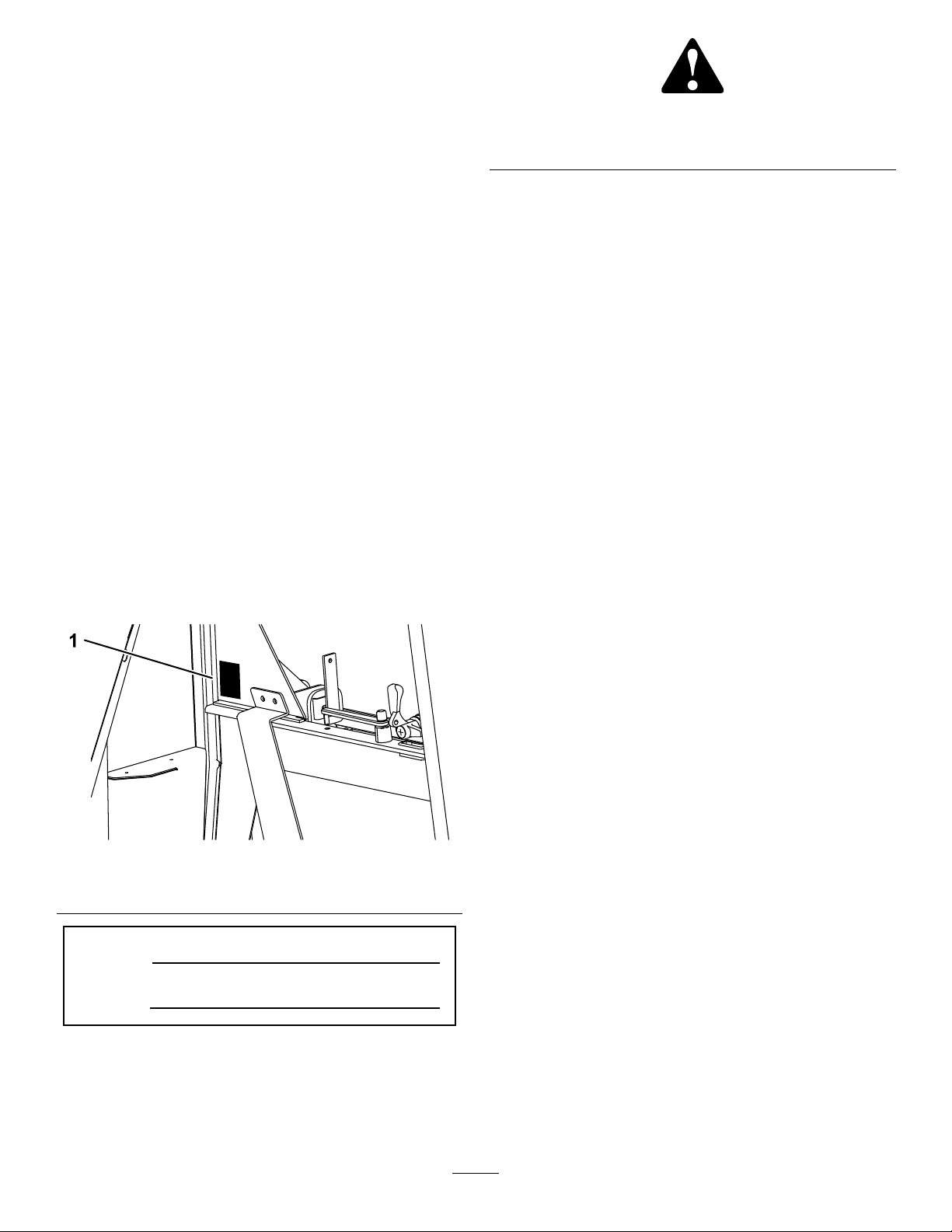
Figure1identiesthelocationofthemodelandserial
numbersontheproduct.Writethenumbersinthe
spaceprovided.
g245764
Figure1
1.Modelandserialnumberlocation
ModelNo.
SerialNo.
Thismanualidentiespotentialhazardsandhas
safetymessagesidentiedbythesafety-alertsymbol
(Figure2),whichsignalsahazardthatmaycause
seriousinjuryordeathifyoudonotfollowthe
recommendedprecautions.
g000502
Figure2
1.Safety-alertsymbol
Thismanualuses2wordstohighlightinformation.
Importantcallsattentiontospecialmechanical
informationandNoteemphasizesgeneralinformation
worthyofspecialattention.
Contents
Safety.......................................................................3
MaximumSlopeAnglesofMowerswith
Cab.................................................................3
SafetyandInstructionalDecals..........................3
ProductOverview.....................................................5
Controls.............................................................5
Specications....................................................7
Attachments/Accessories...................................7
Operation..................................................................7
UsingtheSunshade...........................................7
UsingtheAirConditionerfortheFirst
Time................................................................7
OperatingtheHeatingandAir-Conditioning
System............................................................8
OperatingtheWindscreenWiperand
Washer...........................................................8
FillingtheScreenWasherBottle.........................8
OperatingtheWindows......................................9
OperatingtheDoors.........................................10
AdjustingtheMirrors..........................................11
Maintenance...........................................................12
RecommendedMaintenanceSchedule(s)...........12
PreparingforMaintenance...............................13
TiltingtheCab...................................................13
LocatingtheFuses...........................................14
CheckingtheAir-ConditionerCompressor
Clutch............................................................15
RemovingtheRoof...........................................15
InstallingtheRoof.............................................16
CheckingtheRefrigerantLevel.........................16
InspectingandCleaningtheCondenser...........16
CheckingtheDrainTubes.................................17
CheckingtheCompressor-FanBelt..................17
CheckingtheRefrigerantPressure...................18
TroubleshootingthePressureReadings...........18
WashingtheMachineandCab.........................18
Storage...................................................................19
Schematics.............................................................20
©2021—TheToro®Company
8111LyndaleAvenueSouth
Bloomington,MN554202
Contactusatwww.Toro.com.
PrintedintheUK
AllRightsReserved

Safety
WARNING
Workingonthemachinewithoutthesafety
supportbracketincreasestheriskofinjuryto
youandothers.
Beforeperformingmaintenanceunderneath
theoperatorplatformandcab,ensurethatthe
safetysupportbracketisinstalled.
WARNING
Theelectricalsystemofthemachinecould
shockyouandcausepersonalinjury.
Beforeworkingonthemachineelectrical
systems,alwaysdisconnectthebattery
terminals(negativeterminalrst)andensure
thatnocontactismadebetweentheterminals
andmetalpartsofthemachine.
Important:Alwaysweartheseatbeltwhenthe
safetycabisinstalled.
Important:RefertoyourmachineOperator’s
Manualforadviceandguidancewhenoperatinga
moweronslopes.
Toensureoptimumperformanceandcontinuedsafety
certicationofthemachine,useonlygenuineT oro
replacementpartsandaccessories.Replacement
partsandaccessoriesmadebyothermanufacturers
couldbedangerous,andsuchusecouldvoidthe
productwarranty.
MaximumSlopeAnglesof
MowerswithCab
Youcantthiscabtothemowerslistedatthefrontof
thisdocument.Whenttedwithacab,eachmower
modelhasadifferentmaximumslopeangleandthis
isstatedonthedecallocatedonthelidofthestorage
podontheleftofthemachine.RefertoSafetyand
InstructionalDecals(page3)forthecorrectmaximum
slopeangledecalforyourmachinewhenttedwith
acab.
SafetyandInstructionalDecals
Safetydecalsandinstructionsareeasilyvisibletotheoperatorandarelocatednearanyarea
ofpotentialdanger.Replaceanydecalthatisdamagedormissing.
decal111-9775
111-9775
1.Crushinghazard—alwaysusethehoodstay.
3

decal134-6005
134-6005
1.Warning—readtheOperator’sManual;whensittinginthe
cab,alwayswearaseatbelt;wearhearingprotection;remove
thekeyfromtheignitionbeforeperformingmaintenance.
3.Tippinghazard—lowerattachmentswhenoperatingon
hills/slopes;driveslowlywhenturning;donotturnsharply
whiletravelingfast;donooperateonslopesgreaterthan15
degrees.
2.Thrownobjecthazard—keepbystandersaway.
decal978004
978004
1.Cooling/air-conditioning
system
2.ReadtheOperator’s
Manual.
4

ProductOverview
g350665
Figure3
1.Wiper3.Rearviewmirrors
2.Adjustablelower
windscreen
4.Doorandlockinghandle
Controls
BlowerControls
Thecontrolsaremountedontherightsideintheroof
lining.
g025784
Figure4
1.3-positionswitchfor
radial-blowerspeed
3.Air-conditionerswitch
2.Temperaturecontroller
ScreenWiperandWasherSwitch
Theswitchismountedontheleftsideintherooflining.
g018467
Figure5
1.Screenwiper/washerswitch
5

InteriorLightSwitch
Pressthefrontoftheinteriorlightswitch(Figure6)to
turnonthelight.Presstherearoftheswitchtoturn
offthelight.
g020349
Figure6
1.Interiorlightswitch
FrontWindowHandle(2)
Youcanopenthefrontwindowforventilation.There
are2handles(Figure7).
g018406
Figure7
1.Frontwindowhandle
RearWindowHandleandProp
Youcanopentherearwindowforventilation.Rotate
therearwindowproptoholdthewindowopen(Figure
8).
g020350
Figure8
1.Rearwindowhandle2.Rearwindowprop
6

Specications
Note:Specicationsanddesignaresubjectto
changewithoutnotice.
AIRCONDITIONER
Coolingperformance4.2kW
RefrigerantR134A
Recommendedquantityofrefrigerant850g(1.87
lb)
Evaporator—volumetricairowoftheblower660m3/h
(23,307
ft3/h)
ELECTRICAL
Operatingvoltage12V
Fuseforradialblower/compressor15A
Fuseforaxialblower25A
COMPRESSOR
DesignationTM-08HS
Directionofrotation(viewingthepulley)clockwise
Operatingspeed700to6000
rpm
Pistondisplacement82
cm3/rev(5
inch3/rev)
Pressure-sideconnection3/4inch
O-ring
Suction-sideconnection7/8inch
O-ring
Magneticclutchoperatingvoltage12V
Magneticclutchpowerconsumption0.45W
RefrigerantoilZXL100
PAG
Refrigerantoilvolumeincompressor150cm3
(9.15inch3)
Refrigerantoil—additionalrequiredtoll
air-conditionersystem
25cm3
(1.53inch3)
Powerconsumptionofair-conditionersystem2.5kW
Attachments/Accessories
AselectionofT oroapprovedattachmentsand
accessoriesareavailableforusewiththemachineto
enhanceandexpanditscapabilities.Contactyour
authorizedT orodistributororgotowww.T oro.comfor
alistofallapprovedattachmentsandaccessories.
Toensureoptimumperformanceandcontinuedsafety
certicationofthemachine,useonlygenuineT oro
replacementpartsandaccessories.Replacement
partsandaccessoriesmadebyothermanufacturers
couldbedangerous,andsuchusecouldvoidthe
productwarranty.
Operation
Note:Determinetheleftandrightsidesofthe
machinefromthenormaloperatingposition.
UsingtheSunshade
Rotatethesunshadeupordown(Figure9)toadjust
thepositionoftheshade.
g347537
Figure9
UsingtheAirConditioner
fortheFirstTime
1.Starttheengine.
2.Switchontheblowerswitch(Figure4).
3.Switchontheair-conditioningswitch(Figure4).
4.Setthetemperaturecontroller(Figure4)tothe
maximumColdsetting(fullclockwisedirection).
Note:After3minutes,theair-outletlouvers
shouldemitcoldair.
5.Adjustthefanspeedandtemperaturecontrolto
achievetherequiredamountofcooling.
7

OperatingtheHeatingand
Air-ConditioningSystem
Important:Topreventthebatterydischarge,
ensuretheair-conditionerswitchisintheOFF
positionbeforeyoushutofftheengine.
Important:Runtheair-conditioningsystem
for15minutesevery14daystokeepthe
compressor-shaftsealslubricated.
1.Toruntheair-conditioner,pressthe
air-conditionerswitchtotheONposition.
Note:Tousetheheatingandair-conditioning
systemtorecirculatecabairorforheatingthe
cab,pressair-conditionerswitchtotheOFF
position.
g025784
Figure10
1.Blower-speedcontrol
(3-position)
3.Air-conditionerswitch
2.Temperaturecontrol
2.Rotatetheblower-speedcontrolforthedesired
airowrate.
3.Rotatethetemperaturecontroltothedesired
heatorcoolsetting.
Note:Whentheair-conditionerswitchis
intheONposition,thethermostatrunsthe
air-conditioningsystemtomaintaintheset
temperature.
4.Adjustthe2air-ductnozzles(Figure11)inthe
ceilingofthecabtodirectairowtodesired
direction.
g347779
Figure11
OperatingtheWindscreen
WiperandWasher
1.Presstherightsideoftheswitchtorunthe
windscreenwipers(Figure12).
g347396
Figure12
1.OFF2.ON/WASH
2.Presstherightsideoftheswitchandholditto
runthewindscreenwasher(Figure12).
3.Presstheleftsideoftheswitchtoshutoffthe
windscreenwipers(Figure12).
FillingtheScreenWasher
Bottle
WARNING
Failuretousewindscreen-washuidwith
antifreezeprotectionincoldweathercould
resultinimpairedwindscreenvisibility,and
increasedtheriskofinjuryoraccident.
Ifyouoperateyourmachinein
temperatures—below5°C(40°F),use
washeruidwithantifreezeprotection.
1.Openthehoodofthemachine.
2.Removethecapfromthewashtank(Figure13).
8

g347397
Figure13
1.Cap(windscreenwashtank)
3.Fillthewashtankwithcleanwaterandthe
recommendedquantityofwindscreen-wash
uid.
4.Installthecaptothewashtank(Figure13).
5.Closeandlatchthehood.
OperatingtheWindows
AdjustingtheWindscreen
OpeningandClosingtheWindscreen
•T oopenthewindscreen,rotatethelatchhandles
counterclockwise(horizontal),andpushthehandle
forward(Figure14).
g347572
Figure14
1.Latchhandle3.Socket
2.Latchpin(rear
shown—latchhandle)
•T oclosethewindscreen,rotatethatthelatch
handlesarehorizontal,pullthelatchhandlesuntil
thewindscreenisseated,androtatethehandles
clockwiseuntiltheyarevertical(Figure14).
PartiallyOpeningtheWindscreen
1.Rotatethelatchhandlescounterclockwise
(horizontal),andpushthehandleforward
2.Aligntherearlatchpinwiththesocket(Figure
15).
g347571
Figure15
1.Latchpin(rear—latchhandle)
3.Rotatethehandlesclockwiseuntiltheyare
vertical(Figure15).
9

AdjustingtheRearWindow
OpeningandClosingtheRearWindow
•T oopentherearwindow,rotatethelatchhandle
(Figure16)counterclockwise.
Note:Thegas/springcylinderpushesthewindow
fullyopen.
g347754
Figure16
1.Latchhandle3.Latchpin(latchhandle)
2.Socket
•T oclosetherearwindow,rotatesothatthelatch
handlesarevertical,pullthelatchhandleuntil
thewindowisseated,androtatethehandles
clockwiseuntilitishorizontal(Figure16).
PartiallyOpeningtheRearWindow
1.Opentherearwindow.
2.Rotatethelatchhandlehorizontal(Figure17).
g347755
Figure17
1.Pin(proprod)2.Windowlatch
3.Rotatethewindowproptothewindowlatch,
andalignthepinoftherodthroughtheholein
thehandle(Figure17).
4.Toclosetherearwindow,liftthepinoftheprop
rodfromthewindowlatch,rotatethepropaway
fromthewindow,pullthewindowclosed,and
secureitwiththewindowlatch.
OperatingtheDoors
Toopenthedoorfromoutsidethecab,pressthedoor
latchhandleknobwhileopeningthedoor(Figure18).
g020379
Figure18
1.Doorlatchhandle2.Doorlatchknob
10

Toopenthedoorfrominsidethecab,pullbackon
thedoorlockreleaseleverwhileopeningthedoor
(Figure19).
g020353
Figure19
1.Doorlock2.Releaselever
AdjustingtheMirrors
Whilethesittingintheseat,haveaanotherperson
adjusttheside-viewmirrorstoprovideyouthebest
viewalongthesideofthemachine(Figure20).
g020380
Figure20
1.Side-viewmirror
11

Maintenance
Note:Determinetheleftandrightsidesofthemachinefromthenormaloperatingposition.
Forallmaintenanceprocedures,parkthemachineonalevelsurface,shutofftheengine,andremovethekey.
RecommendedMaintenanceSchedule(s)
MaintenanceService
IntervalMaintenanceProcedure
Aftertherst100hours•Checkallconnectionsfortightness.
Every250hours
•Checktheair-conditionercompressorclutchforcorrectoperation.
•Checkthewaterdrainforblockage,andcleanitasnecessary.
•Examinetheconditionoftheelectricalcables.
•Examinetheconditionandtightnessoftheelectricalconnectors.
Every500hours
•Checkthecompressor-fanbeltconditionandtension,andadjustitasnecessary.
•Examinethehoselinesforabrasionandgeneralcondition.
•Checkallconnectionsforleaks(contactyourauthorizedTorodistributorforservice).
•Examinetheconditionoftheclimaticunitinthecabroof,andcheckthepartsfor
tightness.
•Checkthecompressorbracketstightnessofttings.
Monthly•Checktherefrigerantlevel(usingthesightglass).
•Inspectandcleanthecondenser.
Every2years
•Changethedryer/lter(contactyourauthorizedTorodistributorforservice).
•Check/replacerefrigerantandoil(contactyourauthorizedT orodistributorfor
service).
WARNING
Workingonthemachinewithoutthecabsupportbracketincreasesyourriskofinjury.
Beforecarryingoutmaintenanceunderneaththeoperatorplatformandcab,installthecab
supportbracket.
CAUTION
Ifyouleavethekeyintheignitionswitch,someonecouldaccidentlystarttheengineand
seriouslyinjureyouorotherbystanders.
Removethekeyfromtheignitionbeforeyoudoanymaintenance.
Important:MaintenanceorrepairsontheheatingsystemshouldbecarriedoutbyanauthorizedToro
distributororaspecialistinvehicleheatingsystems.
Important:Allworkontherefrigerantpartoftheair-conditioningsystemshouldbecarriedoutby
qualiedpersonnel.
•Youcanusetheair-conditioningsystemformanymonthsofthecuttingseason.Followtheregularprescribed
maintenancetoprolongthelifeofthesystemandensureefcientoperation.Failuretocarryoutthe
prescribedanddocumentedmaintenancecouldinvalidatethewarrantyonthesystemanditscomponents.
•Eveniftheair-conditioningsystemisusedinfrequently,followthemaintenanceschedule,asagingand
refrigerantlosscanoccurwithtime.
•Lowlevelsofrefrigerantcanreducetheefciencyoftheair-conditioningunit.
•Extremelylowlevelscancausethelow-pressureswitchtoshutdownthesystem.
•T ochecktherefrigerantlevel,thereisanintegratedsightglassinthecollectingtank.Afterlling,runthe
systemfor5minutestoallowallairbubblestobepurgedfromthesystem.Checkthelevelafterthisperiod
andtopupisnecessary.Theoccasionalairbubblecanbeaccepted.
12

Important:Donotspillcompressoroilonthevehiclesurface.Itcancausediscolorationofvehicle
paintanddeteriorationofacrylicorABSplasticcomponents.
•Whenattachingtherefrigeranthoses,oilthesealingringswithrefrigerantoil.
•Afterremovalofrefrigeranthosesfromtheair-conditionersystem,alwaysreplacetheO-ringswithnewones
speciedforrefrigerant134A.
•Whentighteningorlooseningttings,alwaysuse2wrenchestopreventthetubesfromtwisting.
PreparingforMaintenance
Preformthefollowingstepseachtimeyoumaintain
themachine.
1.Movethemachinetoalevelsurface.
2.Engagetheparkingbrakeandlowerthecutting
units.
3.Shutofftheengineandremovethekey.
4.Waitforallmovingpartstostop.
TiltingtheCab
Youcantiltthecabforaccessundertheoperator
platformforcleaningandmaintenance.
Thecabandtheoperatorplatformtilttogetheras
asingleunit.Theangleoftiltislessthanthatofa
platformwithoutacab.Thisistoensurethat,owingto
theweightandpositionofthetiltedcab,themachine
hassufcientstabilitywhenyoutiltthecab.
TiltingtheCabForward
1.Ensurethattherearwidowisshutandlocked.
2.Atthecrossbeamnearthebackofthecab,
removethe2hairpinsthatsecurethelatchpins
tothecabsupports.
3.Rotatethelatch-pinhandlessothattheypoint
upward(Figure21).
g347806
Figure21
1.Latch-pinhandle—rotatedupward(vertical)
4.Slidethelatchpinsinboard,andremovethem
fromthecabsupports.
Note:Ifthelatchpinsaredifculttoremove,
movethehandlesofthelatchpinsbackand
forthtohelpfreethepinsfromtheangeholes
andbeambracketholes.
5.Ateithersidesofthecab,slowlyliftthegrab
handleonrearcornerpostuntilthecabisfully
raised.
Note:Gasspringliftcylindershelpyouraise
thecab,andstopitfromtiltingfurtherwhenit
isfullyraised.
6.Removethecab-supportbracketfromthe
storagecompartment.
g036556
Figure22
1.Safetysupportbracket
7.Ateithersideofthemachine,aligntheholein
thecab-supportbracketwiththeholesinthe
cross-beambracket,andsecurethesupport
13

brackettothebeambracketwithalatchpinand
hairpin.
g347419
Figure23
1.Latchpins3.Cabsupportbracket
2.Cab-frameange4.Cross-beambracket
8.Rotatethecabsupportbrackettowardthecab
sothatitalignsbetweenthecab-frameanges,
andrestsagainstthebackofthecabframe
(Figure23).
9.Inserttheotherlatchpinthroughtheholesinthe
cab-frameange,andsecurethelatchpintothe
angeswiththehairpin(Figure23).
LoweringtheCab
1.Removethe2hairpinsandlatchpinsthat
securethecabsupportbrackettothecaband
thecross-beambracket,andremovethecab
support.
2.Ateithersidesofthecab,slowlypulldownthe
grabhandleontherearcornerpostuntilthecab
isfullylowered.
3.Aligntheholesinthecab-frameangeandthe
holesinthecross-beambracket(Figure24).
g347806
Figure24
1.Latchpin—rotatedupward(vertical)
4.Insertthe2latchpins(Figure24)throughthe
holesinthecab-frameangesandcross-beam
brackets.
Note:Ifthelatchpinsaredifculttoinsert,
movethehandlesofthelatchpinsbackand
forthtohelpalignthepinstotheangeholes
andbeambracketholes.
5.Rotatethelatch-pinhandleshorizontal(Figure
25),andsecurethelatchpinswiththe2hairpins.
g018408
Figure25
1.Latch-pinhandle—rotateddownward(horizontal)
6.Stowthecab-supportbracketinthestorage
compartment.
LocatingtheFuses
Thecabfusesarelocatedinthefuseboxinthecab
headliner(Figure26).
g036558
Figure26
1.Cabfusebox
Note:Thefuseidenticationnumbersaremolded
intothefuse-boxcover.
14

g350748
Figure27
1.3A(constant
power—radioandinterior
light)
5.7.5Amp(washer/wiper)
2.10A(switched
power—radio)
6.5A(A/Ccompressor
clutch)
3.25A(rearfansrelay)7.5A(temperaturecontrol)
4.15A(blowerfans)8.Empty
Checkingthe
Air-Conditioner
CompressorClutch
ServiceInterval:Every250hours
1.Unlatchandopenthehood(Figure36).
g347425
Figure28
2.Haveanotherpersonsitintheoperator’s
seat,rotatethetemperaturecontroltothecold
position,andpresstheair-conditionerswitchto
theONandOFFpositions(Figure29).
g347426
Figure29
1.Temperaturecontrol2.Air-conditionerswitch
3.Atthebackofthemachine,listenforthe
compressorclutch(Figure30)engagingand
disengaging(clicking).
g019082
Figure30
1.Compressorclutch
4.Presstheair-conditionerswitch(Figure29)to
theOFFposition.
Important:Topreventthebatterydischarge,
ensuretheair-conditionerswitchisinthe
OFFposition.
RemovingtheRoof
1.Removethe4bolts,4washers,and4sealsthat
securetherooftothecab(Figure31).
Note:Donotremovethe8boltsaroundthe
fans.
Important:Thefansaremountedtothe
roof.
15

g347511
Figure31
1.Cabroof4.Washer
2.Fans5.Seal
3.Bolt
2.Disconnectthewire-harnessconnectorsateach
ofthefans.
3.Carefullyremovetherooffromthecab.
InstallingtheRoof
1.Positiontheroofontotheframeofthecab.
2.Connectthewire-harnessconnectorsateach
ofthefans.
3.Aligntheholesintheroofwiththeclipnutsof
thecabframe.
4.Assembletherooftothecabwiththe4bolts,
4washers,and4seals(Figure31)thatyou
removedinstep1.
CheckingtheRefrigerant
Level
ServiceInterval:Monthly(usingthesightglass).
Checktherefrigeranttoassureitisatthecorrectlevel
forair-conditioneroperation.
1.Removethehardwaresecuringtheroof;referto
RemovingtheRoof(page15).
Note:Donotremovetheroof.
2.Ensurethattheparkingbrakeisengaged,start
theengine,rotatethetemperaturecontrolto
thecoldposition,andpresstheair-conditioner
switchtotheONpositions(Figure32).
g347426
Figure32
1.Temperaturecontrol2.Air-conditionerswitch
3.Idletheenginefor5minutestoallowthe
air-conditioningsystemtopurgeairbubbles
fromtherefrigerant.
4.Movetheroofenoughtoaccessthe
collecting-ltertank(Figure33).
g347510
Figure33
1.Backofthemachine2.Refrigerant-levelsight
glass(collecting-lter
tank)
5.Attheroof,observetherefrigerant-levelsight
gaugeofthecollecting-ltertank(Figure33).If
therearemorethattheoccasionalbubbleseen
throughthesightglass,contactyourauthorized
Torodistributorforservice.
Note:Ifyouseeanoccasionalairbubble,
therefrigerant-levelisacceptable.Asthe
refrigerantlevellowers,youwillseemoreair
bubblespassingthroughthesightglass.Low
levelsofrefrigerantreducetheair-condition
effectiveness.
Important:Anextremelylowrefrigerant
levelcausesthelow-pressureswitchtoshut
downtheair-conditioner.
6.Presstheair-conditionerswitch(Figure32)to
theOFFpositionandshutofftheengine.
Important:Topreventthebatterydischarge,
ensuretheair-conditionerswitchisinthe
OFFposition.
InspectingandCleaning
theCondenser
ServiceInterval:Monthly
1.Removetherooffromthecab;refertoRemoving
theRoof(page15).
16

2.Examinethensofthecondenserand
evaporatorforaccumulatingdustanddebris.
g350713
Figure34
1.Backofthemachine3.Fanwireharness
2.Condenser
3.Ifneeded,cleanthecondenserandevaporator
nswithcompressedairintheoppositedirection
ofthenormalairow.Ifthereisanybuildupof
greasydeposits,cleanitwithanon-abrasive
soapsolution.
4.Installthecabroof;refertoInstallingtheRoof
(page16).
CheckingtheDrainTubes
ServiceInterval:Every250hours
Thewaterdrainsareclearplastictubesthatconnect
totheblowerevaporatorinthecabroof.Thedrain
tubesroutedownbothfrontcabApillars,anddrain
waterfromtheevaporator.
g019083
Figure35
Frontofthecab.
1.Draintube
1.Checkthedraintubesforblockages.
2.Ifthetubeisblocked,useaexiblecleaningtool,
suchasapipecleaner.Ifneeded,disconnect
thetubefromthecondenser-draintting,and
blowoutthetubewithcompressedair.
Checkingthe
Compressor-FanBelt
ServiceInterval:Every500hours
1.Unlatchandopenthehood(Figure36).
g347425
Figure36
2.Checkbelttensionbyapplying40N(9lb)of
forceonthebelt(Figure37),midwaybetween
theenginepulleyandthecompressorpulley.
Note:Thebeltisproperlytensionedifthebelt
deects10mm(3/8inch).
g019081
Figure37
1.Compressor2.Checkthebeltdeection
here.
3.Ifbeltdeectionisgreaterthanorlessthat
10mm(3/8inch),loosentheupperandlower
compressor-mountingbolts.
4.Rotatethecompressortoincreaseordecrease
thebelttension,andtightenthebolts.
17

5.Repeatstep2toensurethatthebelttensionis
correct.
6.Closethehood,andlatchit.
CheckingtheRefrigerant
Pressure
Whenusingtheair-conditioningsystemtheoperating
pressureisdifferentonthesuction(lowpressure)
sideandthepressure(highpressure)sideofthe
compressor;refertoFigure38.
Thispressuredifferenceisinuencedbythespeed
ofthecompressor,theinsidetemperatureofthe
vehicle,theoutsideairtemperatureandtherelative
airhumidity.
Pressuresthatdifferfromthoseinthetablebelow
indicateapossiblefaultinthesystem.
Tocheckthepressures,setthecompressorspeedto
2000rpmwithanairtemperaturebetween20and
40degreesC(68and104degreesF).Operatethe
bloweratposition3(fastestspeedsetting).
g350689
Figure38
1.Redcap(high-pressure
port)
2.Bluecap(low-pressure
port)
SystemRefrigerantPressures
Outside
Temperature
Low-Pressure
Side
High-Pressure
Side
1.7to2.1bar10to14bar
20°C(68°F)
(24.7to30.5psi)(145to203psi)
1.8to2.2bar12to16bar
25°C(77°F)
(26.1to31.9psi)(174to232psi)
1.9to2.3bar14to18bar
30°C(86°F)
(27.6to33.4psi)(203to261psi)
Troubleshootingthe
PressureReadings
Duringthecompressiontest,deviationsfromthe
valuesinthetablemaybemeasured.Locatingthe
causecandeterminewhetherapartrequiresrepair
orreplacement.
Thefollowingisashortlistofsomepressuredeviation
thatmaybemeasuredandsomepossiblecauses.
•Pressureonhigh-pressuremanometertoo
high
–Theairvolumeinthecondenseristoosmall.
–Refrigerantquantityistoohigh
–Thedryer/lterisblocked.
•Pressureonhigh-pressuremanometeristoo
low
–Therefrigerantquantityistoolow(checkthe
sightglass).
–Thecompressorspeedistoolow(checkthe
drivebeltforslip/tension).
–Thereisafaultwiththecompressor.
•Pressureonlow-pressuremanometertoohigh
–Theexpansionvalveisincorrect.
–Thecompressorspeedistoolow(checkthe
drivebeltforslip/tension).
–Thereisafaultwiththecompressor.
•Pressureonlow-pressuremanometertoolow
–Thereisrestrictioninthesuctionorpressure
hoses.
–Theexpansionvalveisincorrect.
–Therefrigerantquantityistoolow(examinethe
sedimentbowl).
–Theairvolumeintheevaporatoristoosmall.
Haveaqualiedpersonexamineandrepairall
deviationsinpressurefromthevaluesinthetable.
Important:Donotallowrefrigeranttodischarge
intotheatmosphere.Beforeopeningor
disconnectingpartsfromtherefrigerantcircuit,
emptytherefrigerantintoaspeciedrecycling
bottle,anddisposeofitcorrectly.
AlwaysusegenuineT orosparepartswhenrepairing
orservicingtheair-conditioningsystem.
WashingtheMachineand
Cab
Whenwashingthemachineandthecab,donotdirect
waterintotheroofarea.
Important:Donotusebrackishorreclaimed
watertocleanthemachine.
18

Storage
RefertothetractionunitOperator’sManualfordetails
onstoringthemachine.
19

Schematics
g350749
1Radialblower
2Expansionvalve
3Evaporator(combinedwithheatexchangerforheating)
4Evaporator—waterdrain
5Compressor
6Condenser
7Axialfans
8Dryer/lter
9Sightglass
10Drain
A/CSystemSchematic(Rev.A)
20
Other manuals for LT-F3000
5
This manual suits for next models
1
Table of contents
Other Toro Lawn Mower manuals

Toro
Toro 71242 User manual

Toro
Toro TimeCutter Z5040 User manual

Toro
Toro TimeCutter MX 5025 User manual

Toro
Toro Recycler 20008 User manual

Toro
Toro Z14-38 TimeCutter Z 74402 User manual

Toro
Toro 21136 User manual

Toro
Toro Reelmaster 5010- H User manual

Toro
Toro 30857 User manual

Toro
Toro Reelmaster 7000-D User manual

Toro
Toro 30070 User manual