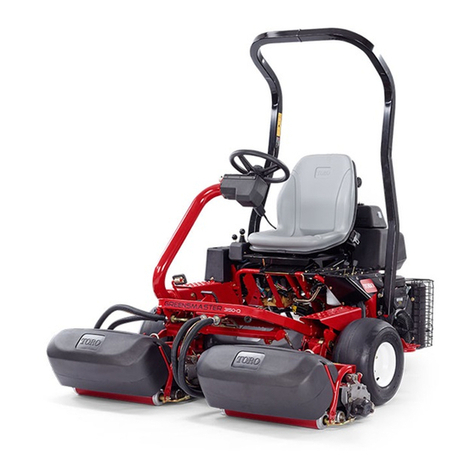
Toro Reelmaster 5410-D User manual

FormNo.3400-966RevB
Reelmaster®5410-Dor5510-D
TractionUnit
ModelNo.03606—SerialNo.316000501andUp
ModelNo.03607—SerialNo.316000501andUp
Registeratwww.Toro.com.
OriginalInstructions(EN)*3400-966*B

ThisproductcomplieswithallrelevantEuropean
directives;fordetails,pleaseseetheseparateproduct
specicDeclarationofConformity(DOC)sheet.
WARNING
CALIFORNIA
Proposition65Warning
Thisproductcontainsachemical
orchemicalsknowntotheStateof
Californiatocausecancer,birthdefects,
orreproductiveharm.
Dieselengineexhaustandsomeofits
constituentsareknowntotheStateof
Californiatocausecancer,birthdefects,
andotherreproductiveharm.
ItisaviolationofCaliforniaPublicResourceCode
Section4442or4443touseoroperatetheengineon
anyforest-covered,brush-covered,orgrass-covered
landunlesstheengineisequippedwithaspark
arrester,asdenedinSection4442,maintainedin
effectiveworkingorderortheengineisconstructed,
equipped,andmaintainedforthepreventionofre.
Introduction
Thismachineisaride-on,reel-bladelawnmower
intendedtobeusedbyprofessional,hiredoperators
incommercialapplications.Itisprimarilydesigned
forcuttinggrassonwell-maintainedlawnsingolf
courses,parks,sportselds,andoncommercial
grounds.Itisnotdesignedforcuttingbrush,mowing
grassandothergrowthalongsidehighways,orfor
agriculturaluses.
Readthisinformationcarefullytolearnhowtooperate
andmaintainyourproductproperlyandtoavoid
injuryandproductdamage.Youareresponsiblefor
operatingtheproductproperlyandsafely.
YoumaycontactTorodirectlyatwww.T oro.com
forproductsafetyandoperationtrainingmaterials,
accessoryinformation,helpndingadealer,orto
registeryourproduct.
Wheneveryouneedservice,genuineT oroparts,or
additionalinformation,contactanAuthorizedService
DealerorToroCustomerServiceandhavethemodel
andserialnumbersofyourproductready.Themodel
andserialnumbersareonaplatemountedonthe
leftsideoftheframeunderthefootrest.Writethe
numbersinthespaceprovided.
ModelNo.
SerialNo.
Thismanualidentiespotentialhazardsandhas
safetymessagesidentiedbythesafety-alertsymbol
(Figure1),whichsignalsahazardthatmaycause
seriousinjuryordeathifyoudonotfollowthe
recommendedprecautions.
g000502
Figure1
1.Safety-alertsymbol
Thismanualuses2wordstohighlightinformation.
Importantcallsattentiontospecialmechanical
informationandNoteemphasizesgeneralinformation
worthyofspecialattention.
©2017—TheToro®Company
8111LyndaleAvenueSouth
Bloomington,MN554202
Contactusatwww.Toro.com.
PrintedintheUSA
AllRightsReserved

Contents
Safety.......................................................................4
SafeOperatingPractices....................................4
SoundPowerLevel............................................6
SoundPressureLevel........................................6
VibrationLevel....................................................6
EngineEmissionCertication.............................6
SafetyandInstructionalDecals..........................7
Setup.......................................................................11
1AdjustingtheTirePressure............................12
2AdjustingtheControl-ArmPosition.................12
3InstallingtheCuttingUnits..............................13
4AdjustingtheTurf-Compensation
Spring...........................................................16
5UsingtheCutting-UnitKickstand....................16
ProductOverview...................................................17
Controls...........................................................17
Specications..................................................25
Attachments/Accessories.................................25
Operation................................................................26
ThinkSafetyFirst..............................................26
CheckingtheEngine-OilLevel..........................26
FillingtheFuelTank..........................................26
CheckingtheCoolingSystem...........................28
CheckingtheHydraulicFluid............................29
CheckingtheReel-to-BedknifeContact............29
ChecktheTorqueoftheWheelNuts.................30
BurnishingtheBrakes.......................................30
StartingandStoppingtheEngine......................30
CuttingGrasswiththeMachine........................30
DieselParticulateFilterRegeneration...............30
AdjustingtheLift-ArmCounterbalance.............39
AdjustingtheLift-ArmTurnaround
Position.........................................................39
PushingorT owingtheMachine........................40
JackingPoints..................................................40
TransportingtheMachine.................................40
LoadingtheMachine........................................41
SettingtheReelSpeed.....................................43
UnderstandingtheDiagnosticLight..................44
CheckingtheInterlockSwitches.......................44
Hydraulic-ValveSolenoidFunctions.................45
OperatingTips.................................................45
Maintenance...........................................................47
RecommendedMaintenanceSchedule(s)...........47
DailyMaintenanceChecklist.............................48
ServiceIntervalChart.......................................49
Lubrication..........................................................49
GreasingtheBearingsandBushings................49
EngineMaintenance...........................................51
ServicingtheAirCleaner..................................51
ServicingtheEngineOil....................................52
ServicingtheDiesel-OxidationCatalyst
(DOC)andtheSootFilter..............................53
FuelSystemMaintenance...................................54
ServicingtheWaterSeparator.........................54
ServicingtheEngine-FuelFilter........................54
CheckingtheFuelLinesand
Connections..................................................55
FuelPick-upTubeScreen.................................55
ElectricalSystemMaintenance...........................55
ServicingtheBattery.........................................55
Fuses................................................................56
DriveSystemMaintenance..................................56
AdjustingtheTractionDriveforNeutral.............56
AdjustingtheRearWheelToe-in.......................57
CoolingSystemMaintenance..............................57
RemovingDebrisfromtheCooling
System..........................................................57
BrakeMaintenance.............................................58
AdjustingtheParkingBrakes............................58
AdjustingtheParking-BrakeLatch....................59
BeltMaintenance................................................60
ServicingtheAlternatorBelt.............................60
HydraulicSystemMaintenance...........................60
ChangingtheHydraulicFluid............................60
ReplacingtheHydraulicFilters.........................61
CheckingtheHydraulicLinesand
Hoses............................................................62
Hydraulic-SystemT estPorts.............................62
CuttingUnitSystemMaintenance........................63
BacklappingtheCuttingUnits...........................63
Storage...................................................................64
PreparingtheTractionUnit...............................64
PreparingtheEngine........................................64
3

Safety
Improperuseormaintenancebytheoperatoror
ownercanresultininjury.Toreducethepotential
forinjury,complywiththesesafetyinstructions
andalwayspayattentiontothesafety-alert
symbol,whichmeansCaution,Warning,or
Danger—personalsafetyinstruction.Failureto
complywiththeinstructionmayresultinpersonal
injuryordeath.
SafeOperatingPractices
ThefollowinginstructionsarefromtheENISO
5395:2013andANSIB71.4-2012.
Training
•ReadtheOperator'sManualandothertraining
materialcarefully.Befamiliarwiththecontrols,
safetysigns,andtheproperuseoftheequipment.
•Neverallowchildrenorpeopleunfamiliarwith
theseinstructionstouseorservicethemower.
Localregulationsmayrestricttheageofthe
operator.
•Nevermowwhilepeople,especiallychildren,or
petsarenearby.
•Keepinmindthattheoperatororuseris
responsibleforaccidentsorhazardsoccurringto
otherpeopleortheirproperty.
•Donotcarrypassengers.
•Alldriversandmechanicsshouldseekand
obtainprofessionalandpracticalinstruction.The
ownerisresponsiblefortrainingtheusers.Such
instructionshouldemphasizethetheneedfor
careandconcentrationwhenworkingwithride-on
machines.
•Theowner/usercanpreventandisresponsible
foraccidentsorinjuriesoccurringtopeopleor
damagetoproperty.
Preparation
•Whilemowing,alwayswearsubstantial,
slip-resistantfootwear,longtrousers,safety
glasses,andearprotection.
•Thoroughlyinspecttheareawheretheequipment
istobeusedandremoveallobjectswhichmaybe
thrownbythemachine.
•Replacefaultysilencers/mufers.
•Evaluatetheterraintodeterminewhataccessories
andattachmentsareneededtoproperlyand
safelyperformthejob.Onlyuseaccessoriesand
attachmentsapprovedbythemanufacturer.
•Checkthattheoperator'spresencecontrols,safety
switchesandshieldsareattachedandfunctioning
properly.Donotoperatethemachineunlessthey
arefunctioningproperly.
SafeHandlingofFuels
•Toavoidpersonalinjuryorpropertydamage,
useextremecareinhandlingfuel.Dieselfuelis
extremelyammableandthevaporsareexplosive.
•Extinguishallcigarettes,cigars,pipes,andother
sourcesofignition.
•Useonlyanapprovedfuelcontainer.
•Neverremovethefuelcaporaddfuelwiththe
enginerunning.
•Allowenginetocoolbeforerefueling.
•Neverrefuelthemachineindoors.
•Neverstorethemachineorfuelcontainerwhere
thereisanopename,spark,orpilotlight,such
asonawaterheateroronotherappliances.
•Neverllcontainersinsideavehicleoronatruck
ortrailerbedwithaplasticliner.Alwaysplace
containersontheground,awayfromyourvehicle
beforelling.
•Removeequipmentfromthetruckortrailerand
refuelitontheground.Ifthisisnotpossible,then
refuelsuchequipmentwithaportablecontainer
ratherthanfromafuel-dispensernozzle.
•Keepthenozzleincontactwiththerimofthefuel
tankorcontaineropeningatalltimesuntilfueling
iscomplete.Donotuseanozzlelockopendevice.
•Iffuelisspilledonclothing,changeclothing
immediately.
•Neveroverllfueltank.Replacethefuelcapand
tightenitsecurely.
Operation
•Donotoperatetheengineinaconnedspace,
wheredangerouscarbonmonoxideandexhaust
gasescancollect.
•Mowonlyindaylightoringoodarticiallight.
•Beforeattemptingtostarttheengine,disengage
allbladeattachmentclutches,shiftintoneutral,
andengagetheparkingbrake.
•Usecounterweight(s)orwheelweightsas
recommendedintheOperator'sManual.
•Stayalertforholesintheterrainandotherhidden
hazards.
•Watchoutfortrafcwhencrossingornear
roadways.
•Stopthebladesrotatingbeforecrossingsurfaces
otherthangrass.
•Whenusinganyattachments,neverdirect
dischargeofmaterialtowardbystandersnorallow
anyonenearthemachinewhileinoperation.
4

•Neveroperatethemachinewithdamagedguards,
shields,orwithoutsafetyprotectivedevicesin
place.Makesurethatallinterlocksareattached,
adjustedproperly,andfunctioningproperly.
•Donotchangetheenginegovernorsettingsor
overspeedtheengine.Operatingtheengineat
excessivespeedmayincreasethehazardof
personalinjury.
•Beforeleavingtheoperator'sposition,dothe
following:
–Stoponlevelground.
–Disengagethepowertake-offandlowerthe
attachments.
–Changeintoneutralandsettheparkingbrake.
–Stoptheengineandremovethekey.
•Disengagedrivetoattachmentswhentransporting
ornotinuse.
•Stoptheengineanddisengagedrivetoattachment
forthefollowing:
–Beforerefuelling
–Beforeremovingthegrasscatcher/catchers
–Beforemakingheightadjustmentunless
adjustmentcanbemadefromtheoperator's
position
–Beforeclearingblockages
–Beforechecking,cleaningorworkingonthe
mower
–Afterstrikingaforeignobjectorifanabnormal
vibrationoccurs.Inspectthemowerfor
damageandmakerepairsbeforerestarting
andoperatingtheequipment
•Reducetheenginespeedsettingduringengine
run-outand,iftheengineisprovidedwithashutoff
valve,turnthefueloffattheconclusionofmowing.
•Keephandsandfeetawayfromthecuttingunits.
•Lookbehindanddownbeforebackinguptobe
sureofaclearpath.
•Slowdownandusecautionwhenmaking
turnsandcrossingroadsandsidewalks.Stop
cylinders/reelsifnotmowing.
•Donotoperatethemoweriftired,ill,orunderthe
inuenceofalcoholordrugs.
•Lightningcancausesevereinjuryordeath.If
lightningisseenorthunderisheardinthearea,do
notoperatethemachine;seekshelter.
•Usecarewhenloadingorunloadingthemachine
intoatrailerortruck.
•Usecarewhenapproachingblindcorners,shrubs,
trees,orotherobjectsthatmayobscurevision.
SlopeSafety
•Slowdownthemachineanduseextracareon
hillsides.Travelintherecommendeddirectionon
hillsides.Turfconditionscanaffectthestabilityof
themachine.
•Avoidstarting,stopping,orturningthemachine
onaslope.Ifthetireslosetraction,disengage
theblade(s)andproceedslowlystraightdownthe
slope.
•Donotturnthemachinesharply.Usecarewhen
reversingthemachine.
•Whenoperatingthemachineonaslope,always
keepallcuttingunitslowered.
•Avoidturningthemachineonslopes.Ifyoumust
turn,turnslowlyandgraduallydownhill,ifpossible.
•Useextracarewhileoperatingthemachinewith
attachments;theycanaffectthestabilityofthe
machine.Followtherecommendationsforusing
themachineonaslopeinthisOperator’sManual.
MaintenanceandStorage
•Keepallnuts,boltsandscrewstighttobesure
thattheequipmentisinsafeworkingcondition.
•Neverstoretheequipmentwithfuelinthetank
insideabuilding,wherefumesmayreachanopen
ameorspark.
•Allowtheenginetocoolbeforestoringinany
enclosure.
•Toreducetherehazard,keeptheengine,
silencer/mufer,batterycompartmentandfuel
storageareafreeofgrass,leaves,orexcessive
grease.
•Checkthegrasscatcherfrequentlyforwearor
deterioration.
•Keepallpartsingoodworkingconditionandall
hardwareandhydraulicttingstightened.Replace
allwornordamagedpartsanddecals.
•Ifthefueltankhastobedrained,dothisoutdoors.
•Becarefulduringadjustmentofthemachineto
prevententrapmentofthengersbetweenmoving
bladesandxedpartsofthemachine.
•Onmulti-cylinder/multi-reelmachines,takecare
asrotatingonecylinder/reelcancauseother
cylinders/reelstorotate.
•Disengagedrives,lowerthecuttingunits,set
parkingbrake,stopengine,andremovekeyfrom
ignition.Waitforallmovementtostopbefore
adjusting,cleaning,orrepairingthemachine.
•Cleangrassanddebrisfromcuttingunits,drives,
silencers/mufers,andenginetohelpprevent
res.Cleanupoilorfuelspills.
•Usejackstandstosupportcomponentswhen
required.
5

•Carefullyreleasepressurefromcomponentswith
storedenergy.
•Disconnectbatterybeforemakinganyrepairs.
Disconnectthenegativeterminalrstandthe
positivelast.Connectpositiverstandnegative
last.
•Usecarewhencheckingthecylinders/reels.Wear
glovesandusecautionwhenservicingthem.
•Keephandsandfeetawayfrommovingparts.If
possible,donotmakeadjustmentswiththeengine
running.
•Chargebatteriesinanopenwellventilatedarea,
awayfromsparkandames.Unplugcharger
beforeconnectingordisconnectingfrombattery.
Wearprotectiveclothinganduseinsulatedtools.
Hauling
•Usecarewhenloadingorunloadingthemachine
intoatrailerortruck.
•Usefull-widthrampsforloadingmachineinto
trailerortruck.
•Tiethemachinedownsecurelyusingstraps,
chains,cable,orropes.Bothfrontandrearstraps
shouldbedirecteddownandoutwardfromthe
machine.
SoundPowerLevel
Theseunitshaveaguaranteedsoundpowerlevel
of103dBA,whichincludesanUncertaintyValue(K)
of1dBA.
Soundpowerlevelwasdeterminedaccordingtothe
proceduresoutlinedinISO11094.
SoundPressureLevel
Theseunitshaveasoundpressurelevelatthe
operator’searof86dBA,whichincludesan
UncertaintyValue(K)of1dBA.
Soundpressurelevelwasdeterminedaccordingto
theproceduresoutlinedinENISO5395:2013.
VibrationLevel
Hand-Arm
Measuredvibrationlevelforrighthand=0.66m/s2
Measuredvibrationlevelforlefthand=0.98m/s2
UncertaintyValue(K)=0.5m/s2
Measuredvaluesweredeterminedaccordingtothe
proceduresoutlinedinENISO5395:2013.
WholeBody
Measuredvibrationlevel=0.31m/s2
UncertaintyValue(K)=0.15m/s2
Measuredvaluesweredeterminedaccordingtothe
proceduresoutlinedinENISO5395:2013.
EngineEmission
Certication
TheengineinthismachineisEPATier4Finaland
stage3bcompliant.
6

SafetyandInstructional
Decals
Safetydecalsandinstructionsare
easilyvisibletotheoperatorandare
locatednearanyareaofpotential
danger.Replaceanydecalthatis
damagedorlost.
decal93-7272
93-7272
1.Cutting/dismembermenthazard,fan—stayawayfrom
movingparts.
decal93-6696
93–6696
1.Storedenergyhazard—readtheOperator'sManual.
decal106-6754
106-6754
1.Warning—donottouchthehotsurface.
2.Cutting/dismembermenthazard,fanandentanglement
hazard,belt—stayawayfrommovingparts.
decal110-0986
110-0986
1.Pressthebrakepedalandparkingbrakepedaltosetthe
parkingbrake.
2.Pressthebrakepedaltoapplythebrake.
3.Pressthetractionpedaltomovethemachineforward.
4.Reelenabledmode
5.Transportmode
decal106-6755
106-6755
1.Enginecoolantunder
pressure.
3.Warning—donottouchthe
hotsurface.
2.Explosionhazard—read
theOperator'sManual.
4.Warning—readthe
Operator'sManual.
decal110-9642
110-9642
1.Storedenergyhazard—readtheOperator'sManual.
2.Movethecotterpintotheholeclosesttotherodbracket
andthenremovetheliftarmandpivotyoke.
7

r:\decal117-0169
117–0169
1.ReadtheOperator'sManual.
2.Powerpoint—10A
3.Headlights—10A
4.Power—10A
5.Enginestart—15A
6.Optionalairrideseatsuspension—10A
7.EnginecomputermanagementC—10A
8.EnginecomputermanagementB—10A
9.EnginecomputermanagementA—10A
decal110-8921
110-8921
1.Tractionunitspeed
2.Slow
3.Fast
decal117-2718
117–2718
decal133-2930
133-2930
1.Warning—readtheOperator'sManual;donotoperatethis
machineunlessyouaretrained.
4.Tippinghazard—slowthemachinebeforeturning;donotturn
athighspeeds;onlydriveonslopeswiththecuttingunits
lowered;alwayswearaseatbelt.
2.Warning—wearhearingprotection.5.Warning—donotparkonslopes;locktheparkingbrake,stop
theengineandremovetheignitionkeybeforeleavingthe
machine.
3.Thrownobjecthazard—keepbystandersasafedistance
awayfromthemachine.
6.Warning—readtheOperator'sManual;donottowthe
machine.
8

decal133-2931
133-2931
1.Warning—readtheOperator'sManual;donotoperatethis
machineunlessyouaretrained.
4.Tippinghazard—donotdriveacrossordownslopesgreater
than15degrees;onlydriveonslopeswiththecuttingunits
lowered;alwayswearaseatbelt
2.Warning—wearhearingprotection.5.Warning—donotparkonslopes;locktheparkingbrake,stop
theengineandremovetheignitionkeybeforeleavingthe
machine.
3.Thrownobjecthazard—keepbystandersasafedistance
awayfromthemachine
6.Warning—readtheOperator'sManual;donottowthe
machine.
decalbatterysymbols
BatterySymbols
Someorallofthesesymbolsareonyourbattery
1.Explosionhazard6.Keepbystandersasafe
distancefromthebattery.
2.Nore,opename,or
smoking
7.Weareyeprotection;
explosivegasescan
causeblindnessandother
injuries.
3.Causticliquid/chemical
burnhazard
8.Batteryacidcancause
blindnessorsevereburns.
4.Weareyeprotection9.Flusheyesimmediately
withwaterandgetmedical
helpfast.
5.ReadtheOperator's
Manual.
10.Containslead;donot
discard.
decal93-6689
93–6689
1.Danger—noriders.
9

decal125-8754
125–8754
1.Headlights6.Slow
2.Engage7.Lowerthecuttingunits
3.Powertake-off(PTO)8.Raisethecuttingunits
4.Disengage9.ReadtheOperator’s
Manual.
5.Fast
decal120-4158
120–4158
1.ReadtheOperator’s
Manual.
3.Engine—preheat
2.Engine—start4.Engine—stop
decal125-2927
125–2927
1.ReadtheOperator’sManualformaintenanceinformation.
10

Setup
LooseParts
Usethechartbelowtoverifythatallpartshavebeenshipped.
ProcedureDescriptionQty.Use
1Nopartsrequired–Adjustthetirepressure.
2Nopartsrequired–Adjustthecontrol-armposition.
Right,fronthoseguide1
3Left,fronthoseguide1Installthecuttingunits.
4Nopartsrequired–Adjusttheturf-compensationspring.
5Cutting-unitkickstand1Installthecutting-unitkickstand.
MediaandAdditionalParts
DescriptionQty.Use
Operator'sManual1ReadtheOperator'sManualbeforeoperatingthemachine.
EngineOperator'sManual1Referenceengineinformation.
PartsCatalog1Referencepartnumbers.
Operatortrainingmaterial1Reviewbeforeoperatingthemachine.
Cuttingperformancepaper1Adjustthecutting-unitbedknifetoreel.
Shim1Adjustthecutting-unitbedknifetoreel.
Note:Determinetheleftandrightsidesofthemachinefromthenormaloperatingposition.
11

1
AdjustingtheTirePressure
NoPartsRequired
Procedure
Thetiresareover-inatedforshipping.Therefore,
releasesomeoftheairtoreducethepressure.
Correctairpressureinthefrontandreartiresis83
to103kPa(12to15psi).
Important:Maintainevenpressureinalltiresto
ensurethatthereisuniformcontactwiththeturf.
2
AdjustingtheControl-Arm
Position
NoPartsRequired
Procedure
Thecontrol-armpositioncanbeadjustedforyour
comfort.
1.Loosenthe2boltssecuringthecontrolarmto
theretainingbracket(Figure2).
g004152
Figure2
1.Controlarm3.Bolt
2.Retainingbrackets
2.Rotatethecontrolarmtothedesiredposition
andtightenthe2bolts.
12

3
InstallingtheCuttingUnits
Partsneededforthisprocedure:
1Right,fronthoseguide
1Left,fronthoseguide
Procedure
1.Removethereelmotorsfromtheshipping
brackets.
Note:Discardtheshippingbrackets.
2.Removethecuttingunitsfromthecartons.
3.Assembleandadjustthecuttingunitsas
describedintheOperator'sManualforthe
cuttingunits.
4.Makesurethatthecounterweight(Figure3)is
installedtotheproperendofeachcuttingunit
asdescribedintheOperator'sManualforthe
cuttingunits.
g003320
Figure3
1.Counterweight
5.Mounttheturf-compensationspringtothesame
sideofthecuttingunitasthereel-drivemotor.
Repositiontheturf-compensationspringas
follows:
Note:Allcuttingunitsareshippedwiththe
turf-compensationspringmountedtotheright
sideofthecuttingunit.
A.Removethe2carriageboltsandnuts
securingtherodbrackettothecutting-unit
tabs(Figure4).
g003949
Figure4
1.Turf-compensationspring3.Springtube
2.Rodbracket
B.Removetheangenutsecuringthe
spring-tubebolttothecarrier-frametab
(Figure4).Removetheassembly.
C.Mountthespring-tubebolttotheopposite
tabonthecarrierframeandsecurewiththe
angenut.
Note:Positiontheboltheadtotheouter
sideofthetabasshowninFigure5.
g003967
Figure5
1.Oppositecarrier-frametab2.Rodbracket
D.Mounttherodbrackettothecutting-unit
tabswiththecarriageboltsandnuts(Figure
5).
Important:Oncuttingunit4(leftfront)
andcuttingunit5(rightfront),usethe
rod-bracket-mountingnutstoinstall
thehoseguidestothefrontofthe
cutting-unittabs(Figure6andFigure7).
Thehoseguidesshouldleantowardthe
centercuttingunit(Figure7andFigure
8).
Note:Wheninstallingorremovingthe
cuttingunits,makesurethatthehairpin
cotterisinstalledinthespring-rodholenext
totherodbracket.Whennotinstallingor
removingthecuttingunits,thehairpincotter
mustbeinstalledintheholeintheendof
therod.
13

g030896
Figure6
1.Cuttingunit15.Cuttingunit5
2.Cuttingunit26.Reelmotor
3.Cuttingunit37.Weight
4.Cuttingunit4
g015160
Figure7
1.Hoseguide(cuttingunit4
shown)
3.Nut
2.Rodbracket
g019284
11
g019284
Figure8
1.Hoseguidesmustleantowardthecentercuttingunit.
6.Lowerallliftarmscompletely.
7.Removethesnapperpinandthecapfromthe
lift-arm-pivotyoke(Figure9).
14

g003975
Figure9
1.Snapperpin2.Cap
8.Forthefrontcuttingunits,slideacuttingunit
undertheliftarmwhileinsertingthecarrier-frame
shaftupintothelift-arm-pivotyoke(Figure10).
g003977
Figure10
1.Liftarm3.Lift-arm-pivotyoke
2.Carrier-frameshaft
9.Usethefollowingprocedureontherearcutting
unitswhentheheightofcutisabove19mm
(3/4inch).
A.Removethelynchpinandwashersecuring
thelift-arm-pivotshafttotheliftarmand
slidethelift-arm-pivotshaftoutofthelift
arm(Figure11).
g003979
Figure11
1.Lynchpinandwasher
B.Insertthelift-armyokeontothecarrier-frame
shaft(Figure10).
C.Insertthelift-armshaftintotheliftarmand
secureitwiththewasherandlynchpin
(Figure11).
10.Insertthecapoverthecarrier-frameshaftand
lift-armyoke.
11.Securethecapandthecarrier-frameshaftto
thelift-armyokewiththesnapperpin(Figure9).
Note:Usetheslotifasteeringcuttingunitis
desiredorusetheholeifthecuttingunitistobe
lockedinposition
12.Securethelift-armchaintothechainbracket
withthesnapperpin(Figure12).
Note:Usethenumberofchainlinksdescribed
intheOperator'sManualforthecuttingunit.
g003948
Figure12
1.Lift-armchain3.Pin
2.Chainbracket
13.Oncuttingunit4(leftfront)andcuttingunit5
(rightfront),insertthereel-motorhosesintothe
respectivehoseguide.
14.Coatthesplineshaftofthereelmotorwithclean
grease.
15.Oilthereel-motorO-ringandinstallitontothe
motorange.
16.Installthemotorbyrotatingitclockwisesothat
themotorangesclearthebolts(Figure13).
15

Note:Rotatethemotorcounterclockwiseuntil
theangesencircletheboltsandthentighten
thebolts.
Important:Makesurethatthereel-motor
hosesarenottwisted,kinked,oratriskof
beingpinched.
g004127
Figure13
1.Reel-drivemotor2.Mountingbolts
4
Adjustingthe
Turf-CompensationSpring
NoPartsRequired
Procedure
Theturf-compensationspringtransfersweightfrom
thefronttotherearroller(Figure14).Thishelps
toreduceawavepatternintheturf,alsoknownas
marcellingorbobbing.
Important:Makespringadjustmentswiththe
cuttingunitmountedtothetractionunit,pointing
straightaheadandloweredtotheground.
1.Makesurethatthehairpincotterisinstalledin
therearholeinthespringrod(Figure14).
g003863
Figure14
1.Turf-compensationspring3.Springrod
2.Hairpincotter4.Hexnuts
2.Tightenthehexnutsonthefrontendofthe
springroduntilthecompressedlengthofthe
springis12.7cm(5inches)for5-inchcutting
unitsor15.9cm(6.25inches)for7-inchcutting
units(Figure14).
Note:Whenoperatingonroughterrain,
decreasethespringlengthby12.7mm(1/2
inch).Thisslightlydecreasestheground
following.
5
UsingtheCutting-Unit
Kickstand
Partsneededforthisprocedure:
1Cutting-unitkickstand
Procedure
Wheneveryouneedtotipthecuttingunittoexpose
thebedknife/reel,propuptherearofthecuttingunit
withthekickstandtomakesurethatthenutsonthe
backendofthebedbar-adjustingscrewsarenot
restingontheworksurface(Figure15).
16

g003985
Figure15
1.Cutting-unitkickstand
Securethekickstandtothechainbracketwiththe
snapperpin(Figure16).
g004144
Figure16
1.Chainbracket3.Cutting-unitkickstand
2.Snapperpin
ProductOverview
g216864
Figure17
1.Enginehood5.Seatadjustments
2.Seat6.Frontcuttingunits
3.Controlarm7.Rearcuttingunits
4.Steeringwheel
Controls
Seat-AdjustingKnobs
Theseat-adjustingleverallowsyoutoadjust
theseatforwardandrearward(Figure18).The
weight-adjustingknobadjuststheseatforyourweight.
Theweightgaugeindicateswhentheseatisadjusted
totheweightoftheoperator.Theheight-adjusting
knobadjuststheseatforyourheight.
g003954
Figure18
1.Weightgauge3.Height-adjustingknob
2.Weight-adjustingknob4.Adjustinglever
17

TractionPedal
Thetractionpedalcontrolstheforwardandreverse
operation(Figure19).Pressthetopofthepedal
tomoveforwardandthebottomtomoverearward.
Groundspeeddependsonhowfaryoupressthe
pedal.Fornoload,maximumgroundspeed,setthe
enginespeedtotheFASTpositionandfullypressthe
pedal.
Tostop,reducefootpressureonthetractionpedal
andallowittoreturntothecenterposition.
g003955
Figure19
1.Tractionpedal4.Brakepedal
2.Mow-speedlimiter5.Parkingbrake
3.Spacers6.Tilt-steeringpedal
Mow-SpeedLimiter
Whenthemow-speedlimiterisippedup,itcontrols
themowspeedandallowsthecuttingunitstobe
engaged(Figure19).Eachspaceradjuststhe
mowingspeedby0.8km/h(0.5mph).Themore
spacersyouhaveonthetopofthebolt,theslowerthe
mowingspeed.Totransportthemachine,ipbackthe
mow-speedlimiterforthemaximumtransportspeed.
BrakePedal
Pressthebrakepedaltostopthemachine(Figure19).
ParkingBrake
Toengagetheparkingbrake,pushdownonthebrake
pedalandpressthetopforwardtolatch(Figure19).
Toreleasetheparkingbrake,pressthebrakepedal
untiltheparking-brakelatchretracts.
Tilt-SteeringPedal
Totiltthesteeringwheeltowardyou,pressthefoot
pedaldown,pullthesteeringtowertowardyouto
themostcomfortableposition,andreleasethepedal
(Figure19).
Engine-SpeedSwitch
Theengine-speedswitchhas2modestochangethe
enginespeed(Figure20).Bymomentarilytappingthe
switch,youcanchangetheenginespeedin100rpm
increments.Ifyouholdtheswitchdown,theengine
automaticallymovestoHighorLowidle,depending
onwhichendoftheswitchyoupress.
1
2
3
4
5
6G021208
g021208
Figure20
1.Lowermow/raisecontrol
lever
4.Enable/disableswitch
2.Keyswitch5.Engine-speedswitch
3.InfoCenter6.Headlightswitch
Enable/DisableSwitch
Usetheenable/disableswitchinconjunctionwiththe
lowermow/raisecontrollevertooperatethecutting
units(Figure20).
InfoCenter
TheInfoCenterLCDdisplayshowsinformationabout
yourmachine,suchastheoperatingstatus,various
diagnostics,andotherinformationaboutthemachine
(Figure20).
KeySwitch
Thekeyswitchhas3positions:OFF,ON/RUN,and
START(Figure20).
LowerMow/RaiseControlLever
Thisleverraisesandlowersthecuttingunitsandalso
startsandstopsthecuttingunitswhenthecutting
unitsareenabledintheMOWmode(Figure20).You
18

cannotlowerthecuttingunitswhenthemow/transport
leverisintheTRANSPORTposition.
HeadlightSwitch
Pivottheswitchdownwardtoturnontheheadlights
(Figure20).
BacklapLevers
Usethebacklapleversinconjunctionwiththelower
mow/raisecontrolleverforbacklappingthereels
(Figure21).
1
g021209
g021209
Figure21
1.Backlaplevers
Hydraulic-Filter-Restriction
Indicator
Withtheenginerunningatnormaloperating
temperature,ensurethattheindicatorisinthegreen
zone(Figure22).Whentheindicatorisinthered
zone,changethehydrauliclters.
g004132
Figure22
1.Hydraulic-lter-restrictionindicator
PowerPoint
Thepowerpointisa12Vpowersupplyforelectronic
devices(Figure23).
g004133
Figure23
1.Powerpoint
UsingtheInfoCenterLCDDisplay
TheInfoCenterLCDdisplayshowsinformationabout
yourmachine,suchastheoperatingstatus,various
diagnostics,andotherinformationaboutthemachine
(Figure24).Thereisasplashscreenandmain
informationscreenoftheInfoCenter.Youcanswitch
betweenthesplashscreenandmaininformation
screen,atanytime,bypressinganyoftheInfoCenter
buttonsandthenselectingtheappropriatedirectional
arrow.
19

1
g020650
2
3
4
TORO
g020650
Figure24
1.Indicatorlight3.Middlebutton
2.Rightbutton4.Leftbutton
•LeftButton,MenuAccess/BackButton—Press
thisbuttontoaccesstheInfoCentermenus.
Youcanuseittobackoutofanymenuyouare
currentlyusing.
•MiddleButton—Pressthisbuttontoscrolldown
menus.
•RightButton—Pressthisbuttontoopenamenu
wherearightarrowindicatesadditionalcontent.
Note:Thepurposeofeachbuttonmaychange
dependingonwhatisrequiredatthetime.Each
buttonislabeledwithanicondisplayingitscurrent
function.
InfoCenterIconDescription
SERVICEDUEIndicateswhenscheduledservice
shouldbeperformed
Enginerpm/status—indicatesthe
enginespeed(rpm)
Hourmeter
Infoicon
Fast
Slow
Fuellevel
Stationaryregenerationisrequired.
Theglowplugsareactive.
Raisethecuttingunits.
Lowerthecuttingunits.
Sitintheseat.
ParkingbrakeisOn.
Therangeishigh(transport).
Neutral
Therangeislow(mow).
Engine-coolanttemperature(°Cor
°F)
Temperature(hot)
ThePTOisengaged.
Notallowed
Starttheengine.
Stoptheengine.
20
Other manuals for Reelmaster 5410-D
3
This manual suits for next models
3
Table of contents
Other Toro Lawn Mower manuals

Toro
Toro Reelmaster 7000-D User manual

Toro
Toro GROUNDSMASTER 345 User manual

Toro
Toro TimeCutter Z4200 User manual

Toro
Toro Recycler 21321 User manual

Toro
Toro 22173 User manual

Toro
Toro 30223TE GROUNDSMASTER 223D User manual

Toro
Toro 74391 User manual

Toro
Toro Z Master 8000 74312 User manual

Toro
Toro Groundsmaster 5900 Series User manual

Toro
Toro 30857 User manual