Toro Recycler 20334 User manual

FormNo.3406-122RevA
22inRecycler®LawnMower
ModelNo.20334—SerialNo.316000001andUp
Operator'sManual
ReplacementpartsareavailablefromanAuthorizedServiceDealeroratwww.shoptoro.com.
Introduction
Thisrotary-blade,walk-behindlawnmowerisintendedto
beusedbyresidentialhomeowners.Itisdesignedprimarily
forcuttinggrassonwell-maintainedlawnsonresidential
properties.Itisnotdesignedforcuttingbrushorfor
agriculturaluses.
Readthisinformationcarefullytolearnhowtooperateand
maintainyourproductproperlyandtoavoidinjuryand
productdamage.Youareresponsibleforoperatingthe
productproperlyandsafely.
YoumaycontactTorodirectlyatwww.Toro.comforproduct
andaccessoryinformation,helpndingadealer,ortoregister
yourproduct.
Wheneveryouneedservice,genuineToroparts,oradditional
information,contactanAuthorizedServiceDealerorToro
CustomerServiceandhavethemodelandserialnumbersof
yourproductready.Figure1identiesthelocationofthe
modelandserialnumbersontheproduct.
Figure1
1.Modelandserialnumberplate
Writetheproductmodelandserialnumbersinthespace
below:
ModelNo.
SerialNo.
Thismanualidentiespotentialhazardsandhassafety
messagesidentiedbythesafety-alertsymbol(Figure2),
whichsignalsahazardthatmaycauseseriousinjuryordeath
ifyoudonotfollowtherecommendedprecautions.
Figure2
1.Safety-alertsymbol
Thismanualuses2wordstohighlightinformation.
Importantcallsattentiontospecialmechanicalinformation
andNoteemphasizesgeneralinformationworthyofspecial
attention.
WARNING
CALIFORNIA
Proposition65Warning
Thisproductcontainsachemicalorchemicals
knowntotheStateofCaliforniatocausecancer,
birthdefects,orotherreproductiveharm.
Theengineexhaustfromthisproduct
containschemicalsknowntotheStateof
Californiatocausecancer,birthdefects,
orotherreproductiveharm.
ItisaviolationofCaliforniaPublicResourceCode
Section4442or4443touseoroperatetheengineonany
forest-covered,brush-covered,orgrass-coveredlandunless
theengineisequippedwithasparkarrester,asdenedin
Section4442,maintainedineffectiveworkingorderorthe
engineisconstructed,equipped,andmaintainedforthe
preventionofre.
ThissparkignitionsystemcomplieswithCanadianICES-002.
Theenclosed
Engine Owner's Man ual
issuppliedfor
informationregardingtheUSEnvironmentalProtection
Agency(EPA)andtheCaliforniaEmissionControl
Regulationofemissionsystems,maintenance,and
warranty.Replacementsmaybeorderedthroughthe
enginemanufacturer.
©2016—TheToro®Company
8111LyndaleAvenueSouth
Bloomington,MN55420
Registeratwww.T oro.com.OriginalInstructions(EN)
PrintedintheUSA
AllRightsReserved*3406-122*A

NetTorque:Thegrossornettorqueofthisenginewas
laboratoryratedbytheenginemanufacturerinaccordance
withtheSocietyofAutomotiveEngineers(SAE)J1940.
Asconguredtomeetsafety,emission,andoperating
requirements,theactualenginetorqueonthisclassofmower
willbesignicantlylower.Gotowww .Toro.comtoview
specicationsonyourmowermodel.
Contents
Introduction..................................................................1
Safety...........................................................................2
GeneralSafety.........................................................2
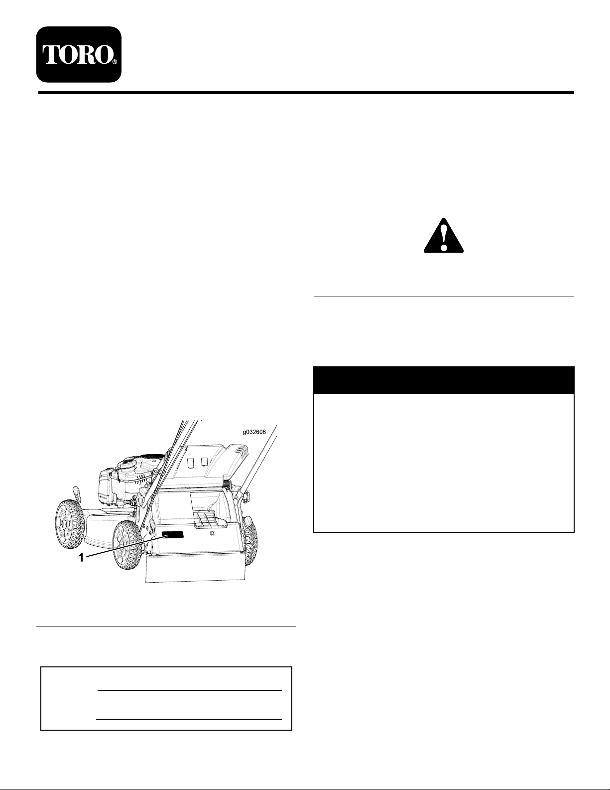
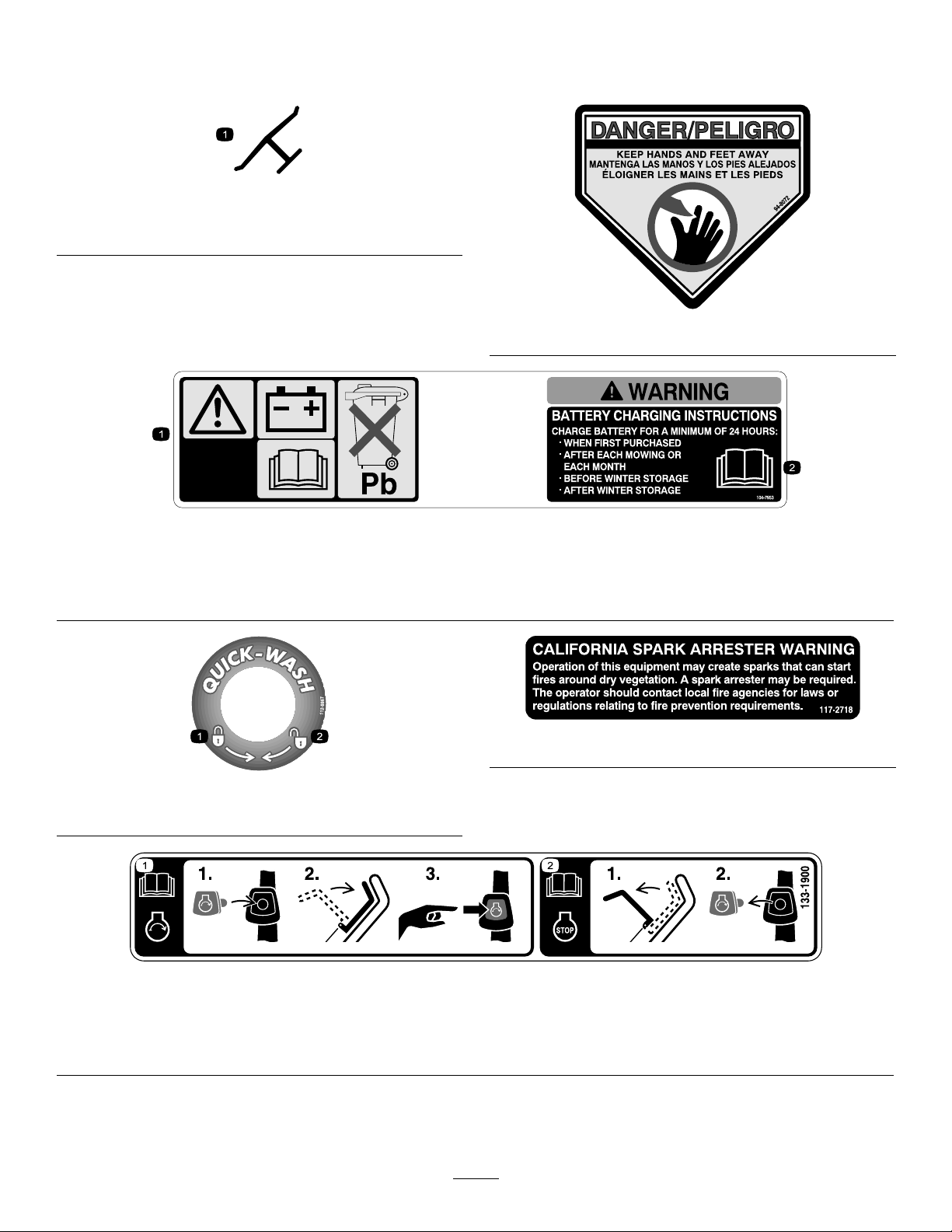
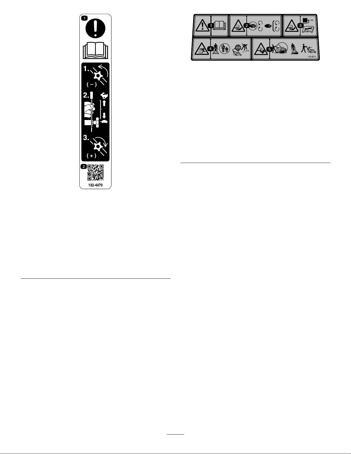
SafetyandInstructionalDecals.................................3
Setup............................................................................5
1AssemblingandUnfoldingtheHandle.....................5
2InstallingtheRecoil-StarterRopeintheRope
Guide.................................................................6
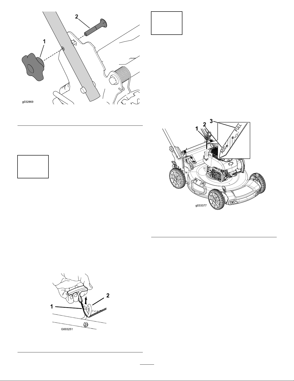
3FillingtheEnginewithOil......................................6
4ChargingtheBattery..............................................7
5AssemblingtheGrassBag......................................7
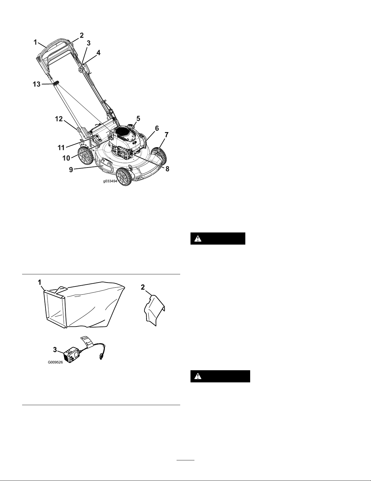
ProductOverview..........................................................8
Operation.....................................................................8
BeforeOperation.......................................................8
BeforeOperationSafety...........................................8
FillingtheFuelTank................................................9
CheckingtheEngine-OilLevel..................................9
AdjustingtheHandleHeight.....................................9
AdjustingtheCuttingHeight....................................10
DuringOperation.....................................................10
DuringOperatingSafety..........................................10
StartingtheEngine.................................................11
UsingtheSelf-PropelDrive.....................................11
StoppingtheEngine...............................................11
RecyclingtheClippings...........................................12
BaggingtheClippings.............................................12
Side-DischargingtheClippings.................................12
OperatingTips......................................................13
AfterOperation........................................................14
AfterOperatingSafety............................................14
CleaningundertheMachine.....................................14
FoldingtheHandle.................................................14
Maintenance.................................................................16
RecommendedMaintenanceSchedule(s)......................16
MaintenanceSafety.................................................16
PreparingforMaintenance.......................................16
ServicingtheAirFilter............................................17
ChangingtheEngineOil.........................................17
ChargingtheBattery...............................................18
ReplacingtheFuse..................................................18
ReplacingtheBlade................................................19
AdjustingtheSelf-PropelDrive................................20
Storage........................................................................21
PreparingtheMachineforStorage............................21
RemovetheMachinefromStorage............................21
Safety
ThismachinehasbeendesignedinaccordancewithANSI
B71.1-2012.
GeneralSafety
Thisproductiscapableofamputatinghandsandfeetand
ofthrowingobjects.Alwaysfollowallsafetyinstructionsto
avoidseriouspersonalinjury.
Usingthisproductforpurposesotherthanitsintendeduse
couldprovedangeroustoyouandbystanders.
•ReadandunderstandthecontentsofthisOperator’s
Manualbeforeyoustarttheengine.Ensurethateveryone
usingthisproductknowshowtouseitandunderstands
thewarnings.
•Donotputyourhandsorfeetnearmovingcomponents
ofthemachine.
•Donotoperatethemachinewithoutallguardsandother
safetyprotectivedevicesinplaceandworkingonthe
machine.
•Keepclearofanydischargeopening.Keepbystandersa
safedistancefromthemachine.
•Keepchildrenoutoftheoperatingarea.Neverallow
childrentooperatethemachine.
•Stopthemachine,shutofftheengine,andremove
theelectric-startbuttonbeforeservicing,fueling,or
uncloggingthemachine.
Improperlyusingormaintainingthismachinecanresult
ininjury.Toreducethepotentialforinjury,complywith
thesesafetyinstructionsandalwayspayattentiontothe
safety-alertsymbol,whichmeansCaution,Warning,or
Danger—personalsafetyinstruction.Failuretocomplywith
theseinstructionsmayresultinpersonalinjuryordeath.
Youcanndadditionalitemsofsafetyinformationintheir
respectivesectionsthroughoutthismanual.
2

SafetyandInstructionalDecals
Important:Safetyandinstructiondecalsarelocatednearareasofpotentialdanger.Replacedamageddecals.
Manufacturer'sMark
1.Indicatesthebladeisidentiedasapartfromtheoriginal
machinemanufacturer.
94-8072
104-7953
Electric-startmodelonly
1.Warning—readtheOperator'sManualforinformationonchargingthebattery;containslead;donotdiscard.
2.ReadtheOperator'sManual.
112-8867
1.Lock2.Unlock
117-2718
133–1900
1.ReadtheOperator’sManualformoreinformationonstarting
theengine—1)Inserttheelectric-startbuttonintotheignition;
2)Engagetheblade-controlbar;3)Pushtheelectric-start
buttontostarttheengine.
2.ReadtheOperator’sManualformoreinformationonstopping
theengine—1)Releasetheblade-controlbar;2)Removethe
electric-startbuttonfromtheignition.
3

132–4470
TractionAdjustment
1.Attention;readthe
Operator'sManual—1)
Loosentheknobbyturning
itcounterclockwise;2)Pull
thecable(s)awayfrom
theenginetodecrease
thetraction,orpushthe
cable(s)towardtheengine
toincreasethetraction;
3)Tightentheknobby
turningitclockwise.
2.ScantheQRcodefor
moreinformationon
tractionadjustment.
131–4514
1.Warning—readtheOperator'sManual.
2.Cutting/dismembermenthazardofhandorfoot,mower
blade—stayawayfrommovingparts;keepallguardsand
shieldsinplace.
3.Cutting/dismembermenthazardofhandorfoot,mower
blade—disconnectthespark-plugwireandreadthe
instructionsbeforeservicingorperformingmaintenance.
4.Thrownobjecthazard—keepbystandersasafedistance
fromthemachine;stoptheenginebeforeleavingthe
operatingposition;pickupanydebrisbeforemowing.
5.Cutting/dismembermenthazardofhandorfoot,mower
blade—donotoperateupanddownslopes;operatesideto
sideonslopes;lookbehindyouwhenbackingup.
4

Setup
Important:Removeanddiscardtheprotectiveplastic
sheetthatcoverstheengineandanyotherplasticor
wrappingonthemachine.
Important:Topreventaccidentalstarting,donotinsert
theelectric-startbuttonintotheelectricstarterswitch
untilyouarereadytostarttheengine.
1
AssemblingandUnfoldingthe
Handle
NoPartsRequired
Procedure
1.Removeandsavethe2handleknobsand2carriage
boltsfromthehandlebrackets(Figure3).
Figure3
1.Handleknob2.Carriagebolt
2.Installthehandleendsontothemowerhousingsothat
thepinattachedtoeachhandlebracketisinthelower
holeofitsrelatedhandleend(Figure4).
Figure4
1.Pin2.Handleend
Note:Thepinswillnotshowthroughtheholesinthe
handleendswhenthehandleisinthefoldedposition.
3.Unfoldthehandletotheoperatingpositionbyrotating
itrearward(Figure5).
Figure5
1.Foldedposition2.Operatingposition
4.Insertthecarriagebolt(withtheboltheadtoward
theinside)throughtheupperorlowersquareholein
handlebracketandtheupperholeinthehandleend
(Figure6).
5

Figure6
1.Handleknob2.Carriagebolt
5.Looselyinstallthehandleknobsontothecarriagebolts.
6.Refertosteps3through5ofAdjustingtheHandle
Height(page9).
2
InstallingtheRecoil-Starter
RopeintheRopeGuide
NoPartsRequired
Procedure
Important:Tostarttheenginesafelyandeasily
wheneveryouusethemachine,installtherecoil-starter
ropeintheropeguide.
Holdtheblade-controlbartotheupperhandleandpullthe
recoil-starterropethroughtheropeguideonthehandle
(Figure7).
Figure7
1.Recoil-starterrope2.Ropeguide
3
FillingtheEnginewithOil
NoPartsRequired
Procedure
Note:Yourmachinedoesnotcomewithoilintheengine,
butitdoescomewithabottleofoil.
Max.ll:0.53L(18oz),type:SAE30detergentoilwithan
APIserviceclassicationofSF,SG,SH,SJ,SL,orhigher.
1.Removethedipstick(Figure8).
Figure8
1.Dipstick3.Fullmarker
2.Addmarker
2.Slowlypouroilintotheoil-lltubeuntiltheoillevel
reachestheFulllineonthedipstick(Figure8).Donot
overll.
3.Installthedipsticksecurely.
6

4
ChargingtheBattery
NoPartsRequired
Procedure
Electric-StartModelOnly
RefertoChargingtheBattery(page18).
5
AssemblingtheGrassBag
NoPartsRequired
Procedure
1.SlipthegrassbagovertheframeasshowninFigure9.
g027257
1
23
Figure9
1.Handle3.Grassbag
2.Frame
Note:Donotslipthebagoverthehandle(Figure9).
2.Hookthebottomchannelofthebagontothebottom
oftheframe(Figure10).
g027258
Figure10
3.Hookthetopandsidechannelsofthebagontothetop
andsidesoftheframe,respectively(Figure10).
7

ProductOverview
Figure11
1.Handle8.Sparkplug
2.Blade-controlbar9.Side-dischargedeector
3.Adjustmentknobforthe
self-propeldrive
10.Oilll/dipstick
4.Electric-startbutton
(electric-startmodelonly)
11.Bag-on-demandlever
5.Fuel-tankcap12.Handleknob(2)
6.Airlter13.Recoil-starthandle
7.Cutting-heightlever(4)
Figure12
1.Grassbag3.Batterycharger
(electric-startmodelonly)
2.Side-dischargechute
Operation
BeforeOperation
BeforeOperationSafety
GeneralSafety
•Becomefamiliarwiththesafeoperationoftheequipment,
operatorcontrols,andsafetysigns.
•Checkthatallguardsandsafetydevices,suchasdeectors
and/orgrasscatcher,areinplaceandworkingproperly.
•Alwaysinspectthemachinetoensurethattheblades,
bladebolts,andcuttingassemblyarenotwornor
damaged.
•Inspecttheareawhereyouwillusethemachineand
removeallobjectsthatthemachinecouldthrow .
•Adjustingthecuttingheightmaybringyouintocontact
withthemovingblade,causingseriousinjury.
–Shutofftheengine,removetheelectric-startbutton,
andwaitforallmovingpartstostop.
–Donotputyourngersunderthehousingwhen
adjustingthecuttingheight.
FuelSafety
DANGER
Fuelisextremelyammableandhighlyexplosive.
Areorexplosionfromfuelcanburnyouand
othersandcandamageproperty.
•Topreventastaticchargefromignitingthefuel,
placethecontainerand/ormachinedirectlyon
thegroundbeforelling,notinavehicleoron
anobject.
•Fillthefueltankoutdoors,inanopenarea,when
theengineiscold.Wipeupanyfuelthatspills.
•Donothandlefuelwhensmokingoraroundan
openameorsparks.
•Storefuelinanapprovedcontainerandkeepit
outofthereachofchildren.
WARNING
Fuelisharmfulorfatalifswallowed.Long-term
exposuretovaporscancauseseriousinjuryand
illness.
•Avoidprolongedbreathingofvapors.
•Keepyourhandsandfaceawayfromthenozzle
andthefuel-tankopening.
•Keepfuelawayfromyoureyesandskin.
8

FillingtheFuelTank
•Forbestresults,useonlyclean,fresh,unleadedgasoline
withanoctaneratingof87orhigher((R+M)/2rating
method).
•Oxygenatedfuelwithupto10%ethanolor15%MTBE
byvolumeisacceptable.
•Donotuseethanolblendsofgasoline,suchasE15
orE85,withmorethan10%ethanolbyvolume.
Performanceproblemsand/orenginedamagemayresult,
whichmaynotbecoveredunderwarranty.
•Donotusegasolinecontainingmethanol.
•Donotstorefueleitherinthefueltankorinfuel
containersoverthewinterunlessfuelstabilizerhasbeen
addedtothefuel.
•Donotaddoiltogasoline.
Important:Toreducestartingproblems,addfuel
stabilizertothefuelallseason,mixingitwithgasoline
lessthan30daysold.
Figure13
CheckingtheEngine-OilLevel
ServiceInterval:Beforeeachuseordaily
1.Movethemachinetoalevelsurface.
2.Removethedipstick,wipeitclean,andfullyinstallthe
dipstick(Figure14).
Figure14
1.Dipstick3.Fullmark
2.Addmark
3.Removethedipstickandchecktheoillevel(Figure14).
IftheoillevelisbelowtheAddmarkonthedipstick,
slowlypouroilintotheoillltubetoraisetheoillevel
totheFullmarkonthedipstick.Donotoverll.
4.Installthedipsticksecurely.
AdjustingtheHandleHeight
Youcanraiseorlowerthehandlein1of2positionsthatis
morecomfortableforyou(Figure15).
Figure15
1.Loosenbothhandleknobsuntilyoucanpushthe
squareedgesofthecarriageboltsoutofthesquare
holesinthehandlebrackets.
2.Pushtheknobsuntiltheyareloose.
3.Movethehandletotheupperorlowerheightposition.
4.Pulltheknobsuntilthesquareedgesofeachcarriage
bolttsintoitsrelatedsquarehole.
5.Tightenthehandleknobsastightasyoucan.
9

AdjustingtheCuttingHeight
WARNING
Adjustingthecuttingheightmaybringyouinto
contactwiththemovingblade,causingserious
injury.
•Stoptheengineandwaitforallmovingparts
tostop.
•Donotputyourngersunderthehousingwhen
adjustingthecuttingheight.
CAUTION
Iftheenginehasbeenrunning,themuferwillbe
hotandcanseverelyburnyou.Keepawayfromthe
hotmufer.
Adjustthecuttingheightasdesired.Setthefrontwheelsto
thesameheightastherearwheels(Figure16).
Note:Toraisethemachine,movethefrontcutting-height
leversrearwardandtherearcutting-heightleversforward.
Tolowerthemachine,movethefrontcutting-heightlevers
forwardandtherearcutting-heightleversrearward.
Figure16
1.Raisethemachine2.Lowerthemachine
Note:Thecutting-heightsettingsare25mm(1inch);35
mm(1-3/8inches);44mm(1-3/4inches);54mm(2-1/8
inches);64mm(2-1/2inches);73mm(2-7/8inches);83mm
(3-1/4inches);92mm(3-5/8inches);and102mm(4inches).
DuringOperation
DuringOperatingSafety
GeneralSafety
•Wearappropriateclothing,includingeyeprotection;
slip-resistant,substantialfootwear;andhearing
protection.Tiebacklonghair,securelooseclothing,and
donotwearjewelry.
•Donotoperatethemachinewhileill,tired,orunderthe
inuenceofalcoholordrugs.
•Thebladeissharp;contactingthebladecanresultin
seriouspersonalinjury.Shutofftheengine,removethe
electric-startbutton,andwaitforallmovingpartstostop
beforeleavingtheoperatingposition.
•Whenyoureleasetheblade-controlbar,theengineshould
shutoffandthebladeshouldstopwithin3seconds.If
not,stopusingyourmachineimmediatelyandcontactan
AuthorizedServiceDealer.
•Operatethemachineonlyingoodvisibilityand
appropriateweatherconditions.Donotoperatethe
machinewhenthereistheriskoflighting.
•Wetgrassorleavescancauseseriousinjuryifyouslipand
contacttheblade.Mowonlyindryconditions.
•Useextremecarewhenapproachingblindcorners,
shrubs,trees,orotherobjectsthatmayblockyourview .
•Watchforholes,ruts,bumps,rocks,orotherhidden
objects.Uneventerraincouldcauseaslip-and-fall
accident.
•Stopthemachineandinspectthebladesafterstrikingan
objectorifthereisanabnormalvibrationinthemachine.
Makeallnecessaryrepairsbeforeresumingoperation.
•Beforeleavingtheoperatingposition,shutofftheengine,
removetheelectric-startbutton,andwaitforallmoving
partstostop.
•Iftheenginehasbeenrunningthemuferwillbehotand
canseverelyburnyou.Keepawayfromthehotmufer.
•Checkthegrasscatchercomponentsandthedischarge
guardfrequentlyandreplacethemwiththemanufacturer’s
recommendedpartswhennecessary.
•UseaccessoriesandattachmentsapprovedbyTheToro
Companyonly.
SlopeSafety
•Mowacrossthefaceofslopes;neverupanddown.Use
extremecautionwhenchangingdirectiononslopes.
•Donotmowonexcessivelysteepslopes.Poorfooting
couldcauseaslip-and-fallaccident.
•Donotmowneardrop-offs,ditches,orembankments.
Youcouldloseyourfootingorbalance.
10

StartingtheEngine
1.Holdtheblade-controlbaragainstthehandle(Figure
17).
Figure17
1.Blade-controlbar
2.Pushtheelectric-startbutton(electric-startmodel
only;refertoFigure18)orpulltherecoil-starthandle
(Figure19).
Note:Iftheelectric-startbuttonhasbeenremoved,
insertitintotheelectricstarter;refertoFigure18
(electric-startmodelonly).
G020174
1
2
3
Figure18
Electricstart
1.Electricstarter3.Insertedelectric-start
button
2.Electric-startbutton
Note:Whenyoupulltherecoil-starthandle,pullit
lightlyuntilyoufeelresistance,thenpullitsharply
(Figure19).Allowtheropetoreturntothehandle
slowly.
Figure19
Recoilstart
Note:Ifthemachinedoesnotstartafterseveral
attempts,contactanAuthorizedServiceDealer.
UsingtheSelf-PropelDrive
Tooperatetheself-propeldrive,simplywalkwithyourhands
ontheupperhandleandyourelbowsatyoursides,andthe
machinewillautomaticallykeeppacewithyou(Figure20).
Figure20
Note:Ifthemachinedoesnotfreelyrollbackwardafter
self-propelling,stopwalking,holdyourhandsinplace,and
allowthemachinetorollacoupleofcentimeters(inches)
forwardtodisengagethewheeldrive.Youcanalsotry
reachingjustundertheupperhandletothemetalhandleand
pushthemachineforwardacoupleofcentimeters(inches).
Ifthemachinestilldoesnotrollbackwardeasily,contactan
AuthorizedServiceDealer.
StoppingtheEngine
ServiceInterval:Beforeeachuseordaily
Tostoptheengine,releasetheblade-controlbar.
Note:Removetheelectric-startbuttonwheneveryouleave
themachine(electric-startmodelonly).
11

Important:Whenyoureleasetheblade-controlbar,
boththeengineandbladeshouldstopwithin3seconds.
Iftheydonotstopproperly,stopusingyourmachine
immediatelyandcontactanAuthorizedServiceDealer.
RecyclingtheClippings
Yourmachinecomesfromthefactoryreadytorecyclethe
grassandleafclippingsbackintothelawn.
Ifthegrassbagisonthemachineandthebag-on-demand
leverisintheBaggingposition,movethelevertothe
Recyclingpositionbeforerecyclingtheclippings;referto
OperatingtheBag-on-DemandLever(page12).Ifthe
side-dischargechuteisonthemachine,removeitbefore
recyclingtheclippings;refertoRemovingtheSide-Discharge
Chute(page13).
BaggingtheClippings
Usethegrassbagwhenyouwanttocollectgrassandleaf
clippingsfromthelawn.
Iftheside-dischargechuteisonthemachine,removeitbefore
baggingtheclippings;refertoRemovingtheSide-Discharge
Chute(page13).Ifthebag-on-demandleverisinthe
Recyclingposition,moveittotheBaggingposition;referto
OperatingtheBag-on-DemandLever(page12).
InstallingtheGrassBag
1.Raiseandholdupthereardeector(Figure21).
Figure21
1.Reardeector3.Grass-bagpin(2)
2.Notches(2)
2.Installthegrassbag,ensuringthatthepinsonthebag
restinthenotchesonthehandle(Figure21).
3.Lowerthereardeector.
RemovingtheGrassBag
Toremovethebag,reversethestepsinInstallingtheGrass
Bag(page12).
OperatingtheBag-on-DemandLever
Thebag-on-demandfeatureallowsyoutoeithercollector
recyclegrassandleafclippingswhilethegrassbagisattached
tothemachine.
•Forbaggingthegrassandleafclippings,pressthebutton
onthebag-on-demandleverandmovetheleverforward
untilthebuttonontheleverpopsup(Figure22).
Figure22
1.Bag-on-demandlever(inbaggingposition)
•Forrecyclingthegrassandleafclippings,pressthebutton
ontheleverandmovetheleverrearwarduntilthebutton
ontheleverpopsup.
Important:Forproperoperation,removeanygrass
clippingsanddebrisfromthebag-on-demanddoorand
thesurroundingopening(Figure23)beforeyoumove
thebag-on-demandleverfrom1positiontoanother.
Figure23
1.Cleanhere
Side-Dischargingthe
Clippings
Usethesidedischargeforcuttingverytallgrass.
Ifthegrassbagisonthemachineandthebag-on-demand
leverisintheBaggingposition,movethelevertothe
Recyclingposition;refertoOperatingtheBag-on-Demand
Lever(page12).
12

InstallingtheSide-DischargeChute
Liftupthesidedeectorandinstalltheside-dischargechute
(Figure24).
Figure24
RemovingtheSide-DischargeChute
Toremovetheside-dischargechute,liftupthesidedeector,
removetheside-dischargechute,andlowertheside-discharge
deector.
OperatingTips
GeneralMowingTips
•Cleartheareaofsticks,stones,wire,branches,andother
debristhatthebladecouldhit.
•Avoidstrikingsolidobjectswiththeblade.Never
deliberatelymowoveranyobject.
•Ifthemachinestrikesanobjectorstartstovibrate,
immediatelystoptheengine,disconnectthewirefromthe
sparkplug,removetheelectric-startbutton,andexamine
themachinefordamage.
•Forbestperformance,installanewbladebeforethe
cuttingseasonbegins.
•ReplacethebladewhennecessarywithaToro
replacementblade.
CuttingGrass
•Cutonlyaboutathirdofthegrassbladeatatime.Donot
cutbelowthe54mm(2-1/8inch)settingunlessthegrass
issparseoritislatefallwhengrassgrowthbeginstoslow
down.RefertoAdjustingtheCuttingHeight(page10).
•Whencuttinggrassover15cm(6inches)tall,mowatthe
highestcuttingheightsettingandwalkslower;thenmow
againatalowersettingforthebestlawnappearance.If
thegrassistoolong,themachinemayplugandcause
theenginetostall.
•Mowonlydrygrassorleaves.Wetgrassandleavestend
toclumpontheyardandcancausethemachinetoplug
ortheenginetostall.
•Beawareofapotentialrehazardinverydryconditions,
followalllocalrewarnings,andkeepthemachinefree
ofdrygrassandleafdebris.
•Alternatethemowingdirection.Thishelpsdispersethe
clippingsoverthelawnforevenfertilization.
•Ifthenishedlawnappearanceisunsatisfactory,try1
ormoreofthefollowing:
–Replacethebladeorhaveitsharpened.
–Walkataslowerpacewhilemowing.
–Raisethecuttingheightonyourmachine.
–Cutthegrassmorefrequently.
–Overlapcuttingswathsinsteadofcuttingafullswath
witheachpass.
–Setthecuttingheightonthefrontwheelsanotch
lowerthantherearwheels.Forexample,setthefront
wheelsat54mm(2-1/8inches)andtherearwheels
at64mm(2-1/2inches).
CuttingLeaves
•Aftercuttingthelawn,ensurethathalfofthelawnshows
throughthecutleafcover.Youmayneedtomakemore
thanasinglepassovertheleaves.
•Iftherearemorethan13cm(5inches)ofleavesonthe
lawn,setthefrontcuttingheight1or2notcheshigher
thantherearcuttingheight.
•Slowdownyourmowingspeedifthemachinedoesnot
cuttheleavesnelyenough.
13

AfterOperation
AfterOperatingSafety
GeneralSafety
•Cleangrassanddebrisfromthemachinetohelpprevent
res.Cleanupoilorfuelspills.
•Allowtheenginetocoolbeforestoringthemachinein
anyenclosure.
•Neverstorethemachineorfuelcontainerwherethereis
anopename,spark,orpilotlight,suchasonawater
heateroronotherappliances.
HaulingSafety
•Removetheelectric-startbuttonbeforeloadingtheunit
forhauling.
•Usecarewhenloadingorunloadingthemachineintoa
trailerortruck.
•Usefull-widthrampsforloadingthemachineintoa
trailerortruck.Donotexceeda15°anglebetweenthe
rampandthetrailerortruck.
•Tiethemachinedownsecurelyusingstraps,chains,cable,
orropes.Bothfrontandrearstrapsshouldbedirected
downandoutwardfromthemachine.
CleaningundertheMachine
ServiceInterval:Beforeeachuseordaily
WARNING
Themachinemaydislodgematerialfromunderthe
machine.
•Weareyeprotection.
•Stayintheoperatingposition(behindthe
handle)whentheengineisrunning.
•Donotallowbystandersinthearea.
Forbestresults,cleanthemachinesoonafteryouhave
completedmowing.
1.Movethemachineontoaatpavedsurface.
2.Stoptheengineandwaitforallmovingpartstostop
beforeleavingtheoperatingposition.
3.Lowerthemachinetoitslowestcutting-heightsetting;
refertoAdjustingtheCuttingHeight(page10).
4.Washouttheareaunderthereardeectorwherethe
clippingsgofromthehousingtothegrassbag.
Note:Washouttheareawiththebag-on-demandin
boththefullyforwardandfullyrearwardpositions.
5.Attachagardenhosethatisconnectedtoawater
supplytothewashoutport(Figure25).
Figure25
1.Washoutport
6.Turnthewateron.
7.Starttheengineandrunituntiltherearenomore
clippingsthatcomeoutfromunderthemachine.
8.Stoptheengine.
9.Shutoffthewateranddisconnectthegardenhose
fromthemachine.
10.Starttheengineandrunitforafewminutestodrythe
undersideofthemachinetopreventitfromrusting.
11.Allowtheenginetocoolbeforestoringthemachine
inanenclosedarea.
FoldingtheHandle
WARNING
Foldingorunfoldingthehandleimproperlycan
damagethecables,causinganunsafeoperating
condition.
•Donotdamagethecableswhenfoldingor
unfoldingthehandle.
•Ifacableisdamaged,contactanAuthorized
ServiceDealer.
1.Removetheelectric-startbutton(Figure26).
14

Figure26
1.Electricstarter2.Electric-startbutton
2.Removeandsavethe2handleknobsand2carriage
boltsfromthehandlebrackets(Figure27).
Important:Routethecablestotheoutsideofthe
handleknobsasyoufoldthehandle.
Figure27
1.Handleknob2.Carriagebolt
3.Foldthehandlebyrotatingitforward(Figure28).
Figure28
1.Operatingposition2.Foldedposition
4.Insertthecarriagebolt(withtheboltheadtowardthe
inside)throughthehandlebracketandtheupperhole
inthehandleend.Ensurethatthesquareedgesofeach
carriagebolttsintotheupperorlowersquareholein
itsrelatedhandlebracket(Figure29).
Figure29
1.Handleknob2.Carriagebolt
5.Looselyinstallthehandleknobsandcarriageboltson
thehandlebrackets.
6.Tounfoldthehandle,referto1Assemblingand
UnfoldingtheHandle(page5).
15

Maintenance
Note:Determinetheleftandrightsidesofthemachinefromthenormaloperatingposition.
RecommendedMaintenanceSchedule(s)
MaintenanceService
IntervalMaintenanceProcedure
Beforeeachuseordaily
•Checktheengine-oillevel.
•Ensurethattheenginestopswithin3secondsafterreleasingtheblade-controlbar.
•Cleangrassclippingsanddirtfromunderthemachine.
Every25hours•Replacetheairlter;replaceitmorefrequentlyindustyoperatingconditions.
•Chargethebatteryfor24hours(electric-startmodelonly).
Yearly
•Replacethebladeorhaveitsharpened(morefrequentlyiftheedgedullsquickly).
•Cleantheair-coolingsystem;cleanitmorefrequentlyindustyoperatingconditions.
Refertoyourengineowner’smanual.
•Refertoyourengineowner’smanualforanyadditionalyearlymaintenance
procedures.
Yearlyorbeforestorage•Chargethebatteryfor24hours(electric-startmodelonly).
•Emptythefueltankbeforerepairsasdirectedandbeforeyearlystorage.
Important:Refertoyourengineowner’smanualforadditionalmaintenanceprocedures.
Note:ReplacementpartsareavailablefromanAuthorizedServiceDealer(gotowww.toro.comtondthenearestdealer)
oratwww .shoptoro.com.
MaintenanceSafety
•Disconnectthespark-plugwirefromthesparkplugand
removetheelectric-startbuttonbeforeperformingany
maintenanceprocedure.
•Wearglovesandeyeprotectionwhenservicingthe
machine.
•Thebladeissharp;contactingthebladecanresultin
seriouspersonalinjury.Weargloveswhenservicingthe
blade.
•Nevertamperwithsafetydevices.Checktheirproper
operationregularly.
•Tippingthemachinemaycausethefueltoleak.Fuelis
ammableandexplosive,andcancausepersonalinjury.
Runtheenginedrytoremovethefuelwithahandpump;
neversiphonthefuel.
PreparingforMaintenance
1.Stoptheengine,removetheelectric-startbutton,and
waitforallmovingpartstostop.
2.Disconnectthespark-plugwirefromthesparkplug
(Figure30).
Figure30
3.Afterperformingthemaintenanceprocedure(s),
connectthespark-plugwiretothesparkplug.
Important:Beforetippingthemachinetochange
theoilorreplacetheblade,allowthefueltankto
rundrythroughnormalusage.Ifyoumusttip
themachinepriortorunningoutoffuel,usea
16

handfuelpumptoremovethefuel.Alwaystipthe
machineontoitsside,withthedipstickdown.
ServicingtheAirFilter
ServiceInterval:Every25hours
1.Upclipthetopoftheair-ltercover(Figure31).
Figure31
1.Clip3.Airlter
2.Air-ltercover
2.Removetheairlter(Figure31).
3.Inspecttheairlter.
Note:Iftheairlterisexcessivelydirty,replaceitwith
anewlter.Otherwise,gentlytaptheairlterona
hardsurfacetoloosendebris.
4.Installtheairlter.
5.Usethecliptoinstalltheair-ltercover.
ChangingtheEngineOil
Changingtheengineoilisnotrequired,butifyoudesire
tochangetheoil,usethefollowingprocedure.
Note:Runtheengineafewminutesbeforechangingthe
oiltowarmit.Warmoilowsbetterandcarriesmore
contaminants.
Max.ll:0.53L(18oz),type:SAE30detergentoilwithan
APIserviceclassicationofSF,SG,SH,SJ,SL,orhigher.
1.RefertoPreparingforMaintenance(page16).
2.Removethedipstick(Figure32).
Figure32
1.Dipstick3.Fullmarker
2.Addmarker
3.Tipthemachineontoitssidewiththeairlterupto
draintheusedoiloutthroughtheoil-lltube(Figure
33).
Figure33
4.Slowlypouroilintotheoil-lltubeuntiltheoillevel
reachestheFulllineonthedipstick(Figure32).Do
notoverll.
5.Installthedipsticksecurely.
6.Disposeoftheusedoilproperlyatalocalrecycling
center.
17

ChargingtheBattery
ServiceInterval:Every25hours
Yearlyorbeforestorage
Electric-StartModelOnly
WARNING
CALIFORNIA
Proposition65Warning
Batteryposts,terminals,andrelated
accessoriescontainleadandleadcompounds,
chemicalsknowntotheStateofCalifornia
tocausecancerandreproductiveharm.
Washhandsafterhandling.
Chargethebatteryfor24hoursinitially,thenmonthly(every
25starts)orasneeded.Alwaysusethechargerinasheltered
area,andchargethebatteryatroomtemperature(about70°
F,or22°C)wheneverpossible.
1.Connectthechargertothemachinewiringharness
locatedbelowtheelectric-startbutton(Figure34).
Figure34
2.Plugthechargeintoawalloutlet.
Note:Whenthebatterynolongerholdsacharge,
recycleordisposeofthelead-acidbatteryaccording
tolocalcodes.
Note:Yourbatterychargermayhavea2-colorLEDdisplay
thatindicatesthefollowingstatesofcharging:
•Aredlightindicatesthatthechargerischargingthe
battery.
•Agreenlightindicatesthatthechargerisfullychargedor
thechargerisdisconnectedfromthebattery.
•Aashinglightthatalternatesbetweenredandgreen
indicatesthatthebatteryisnearlyfullycharged.Thisstate
lastsonlyafewminutesuntilthebatteryisfullycharged.
ReplacingtheFuse
Electric-StartModelOnly
Note:Ifthebatterydoesnotchargeortheenginedoesnot
runwiththeelectricstarter,thefusemaybeblown.Replace
itwitha40Aplug-intypefuse.
1.RefertoPreparingforMaintenance(page16).
2.Raisethereardeectorandlocatethebattery
compartment(Figure35).
Note:Thereisanadhesive-backedcoveringthat
protectsthebatterycompartment.
Figure35
1.Reardeector3.Battery
2.Screw4.Batterycompartment
3.Wipeawayanydebrisinthebatterycompartmentarea
andremovetheadhesive-backedcovering.
4.Removethescrewthatsecuresthebattery
compartment,pulloutthebattery,andlocatethefuse
(Figure35andFigure36).
18

1
2
3
g030022
Figure36
1.Batterycover3.Fuseholder
2.Fuse
5.Replacethefuseinthefuseholder(Figure36).
Note:Yourmachinecomeswithasparefuseattached
tothebattery-chargerbox(Figure37).
2
g030053
1
Figure37
1.Batterycompartment2.Battery-chargerbox
6.Installthebatterycompartmentwiththescrewthat
youremovedinstep4.
7.Installthecoveringoverthebatterycompartment.
8.Lowerthereardeector.
ReplacingtheBlade
ServiceInterval:Yearly
Important:
Y ou will need a torque wr ench to install the
blade pr oper l y .
Ifyoudonothaveatorquewrenchorare
uncomfortableperformingthisprocedure,contactan
AuthorizedServiceDealer.
Examinethebladewheneveryourunoutofgasoline.Ifthe
bladeisdamagedorcracked,replaceitimmediately.Ifthe
bladeedgeisdullornicked,haveitsharpenedandbalanced,
orreplaceit.
WARNING
Thebladeissharp;contactingthebladecanresult
inseriouspersonalinjury.
Weargloveswhenservicingtheblade.
1.RefertoPreparingforMaintenance(page16).
2.Tipthemachineontoitssidewiththedipstickdown.
3.Useablockofwoodtoholdthebladesteady(Figure
38).
Figure38
4.Removetheblade,savingallmountinghardware
(Figure38).
5.Installthenewbladeandallmountinghardware
(Figure39).
19

Figure39
Important:Positionthecurvedendsoftheblade
topointtowardthemowerhousing.
6.Useatorquewrenchtotightenthebladeboltto82
N∙m(60ft-lb).
Important:Abolttorquedto82N∙m(60ft-lb)is
verytight.Whileholdingthebladewithablock
ofwood,putyourweightbehindtheratchetor
wrenchandtightentheboltsecurely.Thisboltis
verydifculttoovertighten.
AdjustingtheSelf-PropelDrive
Wheneveryouinstallanewself-propelcableorifthe
self-propeldriveisoutofadjustment,adjusttheself-propel
drive.
1.Turntheadjustmentknobcounterclockwisetoloosen
thecableadjustment(Figure40).
g027709
Figure40
1.Handle(leftside)3.Self-propel-drivecable
2.Adjustmentknob
2.Adjustthetensiononthecable(Figure40)bypullingit
backorpushingitforwardandholdingthatposition.
Note:Pushthecabletowardtheenginetoincrease
thetraction;pullthecableawayfromtheengineto
decreasethetraction.
3.Turntheadjustmentknobclockwisetotightenthe
cableadjustment.
Note:Tightentheknobrmlybyhand.
20
Table of contents
Other Toro Lawn Mower manuals

Toro
Toro ProLine 22158 User manual

Toro
Toro 30827 User manual

Toro
Toro Groundsmaster 3280-D User manual

Toro
Toro Recycler 20960 User manual

Toro
Toro Air Cool Z Master 74090 User manual

Toro
Toro REELMASTER 6700 D User manual

Toro
Toro TurfMaster 22205TE User manual

Toro
Toro 30410 User manual

Toro
Toro 30809 User manual

Toro
Toro Groundsmaster 4010-D User manual

Toro
Toro Recycler 20331 User manual

Toro
Toro 75304 User manual

Toro
Toro 74490 User manual

Toro
Toro TimeCutter 77404 User manual

Toro
Toro 74024 User manual

Toro
Toro 03200 Reelmaster 3100-D User manual

Toro
Toro 71226 User manual

Toro
Toro 74271 User manual

Toro
Toro Reelmaster 5100-D User manual

Toro
Toro TimeCutter SW 4200 User manual