Toro Reelmaster 3105-D User manual

FormNo.3444-866RevC
Reelmaster®3105-DTractionUnit
ModelNo.03174—SerialNo.400000000andUp
Registeratwww.Toro.com.
OriginalInstructions(EN)*3444-866*

ThisproductcomplieswithallrelevantEuropean
directives.Fordetails,pleaseseetheseparate
productspecicDeclarationofConformity(DOC)
sheet.
ItisaviolationofCaliforniaPublicResourceCode
Section4442or4443touseoroperatetheengineon
anyforest-covered,brush-covered,orgrass-covered
landunlesstheengineisequippedwithaspark
arrester,asdenedinSection4442,maintainedin
effectiveworkingorderortheengineisconstructed,
equipped,andmaintainedforthepreventionofre.
Theenclosedengineowner’smanualissupplied
forinformationregardingtheUSEnvironmental
ProtectionAgency(EPA)andtheCaliforniaEmission
ControlRegulationofemissionsystems,maintenance,
andwarranty.Replacementsmaybeorderedthrough
theenginemanufacturer.
WARNING
CALIFORNIA
Proposition65Warning
Dieselengineexhaustandsomeofits
constituentsareknowntotheStateof
Californiatocausecancer,birthdefects,
andotherreproductiveharm.
Batteryposts,terminals,andrelated
accessoriescontainleadandlead
compounds,chemicalsknownto
theStateofCaliforniatocause
cancerandreproductiveharm.Wash
handsafterhandling.
Useofthisproductmaycauseexposure
tochemicalsknowntotheStateof
Californiatocausecancer,birthdefects,
orotherreproductiveharm.
Introduction
Thismachineisaride-on,reel-bladelawnmower
intendedtobeusedbyprofessional,hiredoperators
incommercialapplications.Itisprimarilydesigned
forcuttinggrassonwell-maintainedturf.Usingthis
productforpurposesotherthanitsintendedusecould
provedangeroustoyouandbystanders.
Readthisinformationcarefullytolearnhowtooperate
andmaintainyourproductproperlyandtoavoid
injuryandproductdamage.Youareresponsiblefor
operatingtheproductproperlyandsafely.
Visitwww.T oro.comformoreinformation,including
safetytips,trainingmaterials,accessoryinformation,
helpndingadealer,ortoregisteryourproduct.
Wheneveryouneedservice,genuineToroparts,or
additionalinformation,contactanAuthorizedService
DealerorT oroCustomerServiceandhavethemodel
andserialnumbersofyourproductready.Figure1
identiesthelocationofthemodelandserialnumbers
ontheproduct.Writethenumbersinthespace
provided.
Important:Withyourmobiledevice,youcan
scantheQRcodeontheserialnumberplate(if
equipped)toaccesswarranty,parts,andother
productinformation.
g259773
Figure1
1.Modelandserialnumberlocation
ModelNo.
SerialNo.
©2023—TheToro®Company
8111LyndaleAvenueSouth
Bloomington,MN554202
Contactusatwww.Toro.com.
PrintedintheUSA
AllRightsReserved

Contents
Safety.......................................................................4
GeneralSafety...................................................4
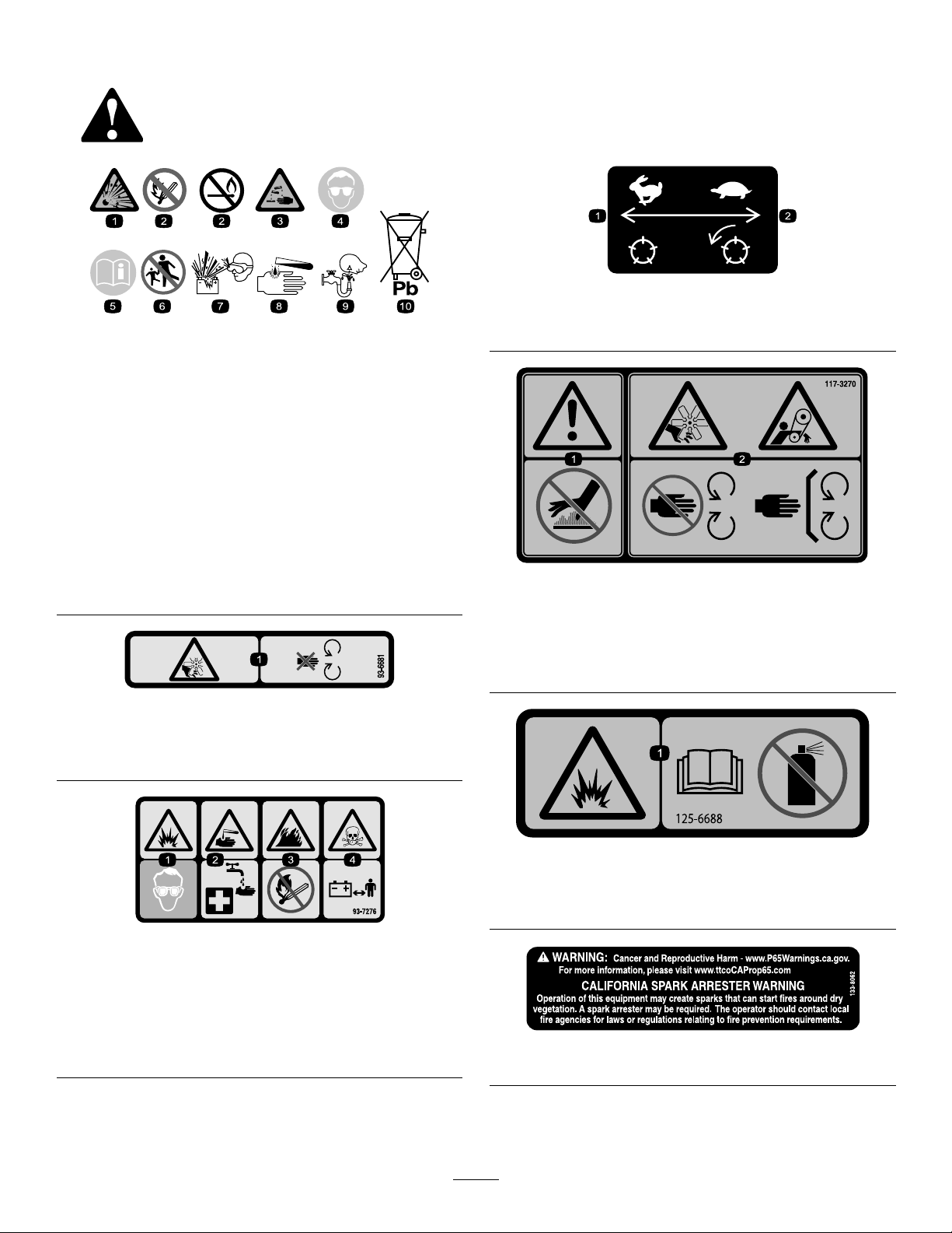
SafetyandInstructionalDecals..........................5
Setup.......................................................................11
1InstallingtheWheels......................................12
2InstallingtheSteeringWheel..........................12
3ChargingandConnectingtheBattery.............13
4InstallingtheRollBar.....................................14
5InstallingtheFrontLiftArms...........................15
6InstallingtheCarrierFramestotheCutting
Units..............................................................17
7InstallingtheCuttingUnits..............................19
8InstallingtheCuttingUnitDrive
Motors...........................................................20
9AdjustingtheLiftArms...................................20
10AdjustingTireAirPressure...........................23
11InstallingtheHoodLatch..............................23
12InstallingtheExhaustGuard........................24
13ApplyingtheCEDecals...............................24
14InstallingtheTipperRollerKit
(Optional)......................................................25
ProductOverview...................................................26
Controls...........................................................26
ControlConsole............................................27
MowerManifold.............................................28
Specications..................................................29
Attachments/Accessories.................................29
BeforeOperation.................................................29
BeforeOperationSafety...................................29
FuelSpecication.............................................30
FillingtheFuelTank..........................................30
PerformingDailyMaintenance..........................30
CheckingtheInterlockSystem..........................31
DuringOperation.................................................32
DuringOperationSafety...................................32
StartingtheEngine...........................................33
ShuttingOfftheEngine.....................................33
CuttingGrasswiththeMachine........................33
DrivingtheMachineinTransportMode.............34
ClipRate(ReelSpeed).....................................35
AdjustingReelSpeed.......................................36
BleedingtheFuelSystem.................................36
OperatingTips.................................................36
AfterOperation....................................................37
AfterOperationSafety......................................37
AfterMowing....................................................37
TowingtheMachine..........................................37
IdentifyingtheTie-DownPoints........................38
HaulingtheMachine.........................................38
Maintenance...........................................................39
MaintenanceSafety..........................................39
RecommendedMaintenanceSchedule(s)...........39
DailyMaintenanceChecklist.............................41
Pre-MaintenanceProcedures..............................42
PreparingforMaintenance...............................42
LiftingtheFrontoftheMachine.........................42
LiftingtheBackoftheMachine.........................42
LiftingtheBackoftheMachine.........................43
RemovingtheBatteryCover.............................43
OpeningtheHood............................................43
Lubrication..........................................................44
GreasingtheBearingsandBushings................44
CheckingtheSealedBearings..........................45
EngineMaintenance...........................................46
EngineSafety...................................................46
EngineOilSpecication....................................46
CheckingtheEngine-OilLevel..........................46
ChangingtheEngineOilandtheFilter..............46
ServicingtheAirCleaner..................................47
FuelSystemMaintenance...................................48
ServicingtheFuelT ank.....................................48
InspectingtheFuelLinesandFittings...............48
DrainingtheWaterSeparator...........................48
ChangingtheFuelFilterCanister......................49
BleedingAirfromtheInjectors..........................49
ElectricalSystemMaintenance...........................50
ElectricalSystemSafety...................................50
ServicingtheBattery.........................................50
ServicingtheFuses..........................................50
DriveSystemMaintenance..................................51
CheckingtheTirePressure...............................51
TorquingtheWheelNuts...................................51
AdjustingtheTractionDriveforNeutral.............51
CoolingSystemMaintenance..............................53
CoolingSystemSafety.....................................53
CoolantSpecication........................................53
CheckingtheCoolantLevel..............................53
CleaningtheEngineCoolingSystem................54
BrakeMaintenance.............................................54
AdjustingtheParkingBrake..............................54
BeltMaintenance................................................55
ServicingtheEngineBelts................................55
ControlsSystemMaintenance.............................56
AdjustingMowGroundSpeed..........................56
AdjustingtheThrottle........................................56
HydraulicSystemMaintenance...........................57
HydraulicSystemSafety...................................57
CheckingtheHydraulicLinesand
Hoses............................................................57
HydraulicFluidSpecications...........................57
CheckingtheHydraulicFluid............................57
HydraulicFluidCapacity...................................58
ChangingtheHydraulicFluid............................58
ChangingtheHydraulicFilter............................59
CuttingUnitSystemMaintenance........................60
BladeSafety.....................................................60
CheckingtheReel-to-BedknifeContact............60
BacklappingtheCuttingUnits...........................60
Cleaning..............................................................62
WashingtheMachine.......................................62
Storage...................................................................62
StorageSafety..................................................62
PreparingtheTractionUnit...............................62
PreparingtheEngine........................................63
3

StoringtheBattery............................................63
Troubleshooting......................................................64
UsingtheStandardControlModule
(SCM)...........................................................64
Safety
GeneralSafety
Thisproductiscapableofamputatinghandsandfeet
andofthrowingobjects.
•Readandunderstandthecontentsofthis
Operator’sManualbeforestartingtheengine.
•Useyourfullattentionwhileoperatingthe
machine.Donotengageinanyactivitythat
causesdistractions;otherwise,injuryorproperty
damagemayoccur.
•Donotputyourhandsorfeetnearmoving
componentsofthemachine.
•Donotoperatethemachinewithoutallguards
andothersafetyprotectivedevicesinplaceand
functioningproperlyonthemachine.
•Keepbystandersandchildrenoutoftheoperating
area.Neverallowchildrentooperatethemachine.
•Shutofftheengine,removethekey,andwait
forallmovementtostopbeforeyouleavethe
operator’sposition.Allowthemachinetocool
beforeadjusting,servicing,cleaning,orstoringit.
Safety-AlertSymbol
Thesafety-alertsymbol(Figure2)showninthis
manualandonthemachineidentiesimportantsafety
messagesthatyoumustfollowtopreventaccidents.
g000502
Figure2
Safety-alertsymbol
Thesafety-alertsymbolappearsaboveinformation
thatalertsyoutounsafeactionsorsituationsand
isfollowedbythewordDANGER,WARNING,or
CAUTION.
DANGERindicatesanimminentlyhazardoussituation
which,ifnotavoided,willresultindeathorserious
injury.
WARNINGindicatesapotentiallyhazardoussituation
which,ifnotavoided,couldresultindeathorserious
injury.
CAUTIONindicatesapotentiallyhazardoussituation
which,ifnotavoided,mayresultinminorormoderate
injury.
Thismanualusestwootherwordstohighlight
information.Importantcallsattentiontospecial
mechanicalinformationandNoteemphasizesgeneral
informationworthyofspecialattention.
4

SafetyandInstructionalDecals
Safetydecalsandinstructionsareeasilyvisibletotheoperatorandarelocatednearanyarea
ofpotentialdanger.Replaceanydecalthatisdamagedormissing.
decalbatterysymbols
BatterySymbols
Someorallofthesesymbolsareonyourbattery.
1.Explosionhazard6.Keepbystandersaway
fromthebattery.
2.Nore,opename,or
smoking
7.Weareyeprotection;
explosivegasescan
causeblindnessandother
injuries.
3.Causticliquid/chemical
burnhazard
8.Batteryacidcancause
blindnessorsevereburns.
4.Weareyeprotection.9.Flusheyesimmediately
withwaterandgetmedical
helpfast.
5.ReadtheOperator's
Manual.
10.Containslead;donot
discard
decal93-6681
93-6681
1.Cutting/dismembermenthazard,fan—stayawayfrom
movingparts.
decal93-7276
93-7276
1.Explosionhazard—weareyeprotection.
2.Causticliquid/chemicalburnhazard—toperformrstaid,
ushwithwater.
3.Firehazard—nore,openames,orsmoking.
4.Poisonhazard—keepchildrenawayfromthebattery.
99-3444
decal99-3444
99-3444
1.Transportspeed—fast2.Mowingspeed—slow
decal117-3270
117-3270
1.Warning—donottouchthehotsurface.
2.Cutting/dismembermenthazard,hand;entanglement
hazard,belt—stayawayfrommovingparts,keepallguards
andshieldsinplace.
decal125-6688
125–6688
1.Explosionhazard—ReadtheOperator’sManual;Donot
usestartinguid.
decal133-8062
133-8062
5

decal136-3702
136-3702
1.Warning—Readthe
Operator’sManual;wear
aseatbelt;donotremove
therollbar.
2.Warning—Donotmodify
therollbar.
decal140-7463
140-7463
Note:Thismachinecomplieswiththeindustrystandard
stabilitytestinthestaticlateralandlongitudinaltestswiththe
maximumrecommendedslopeindicatedonthedecal.Reviewthe
instructionsforoperatingthemachineonslopesintheOperator’s
Manualaswellastheconditionsinwhichyouwouldoperatethe
machinetodeterminewhetheryoucanoperatethemachineinthe
conditionsonthatdayandatthatsite.Changesintheterraincan
resultinachangeinslopeoperationforthemachine.
1.Tippinghazard—donotdriveacrossslopesgreaterthan
14°.
decal136-3717
136-3717
1.Reelspeed5.11-bladereeladjustment
2.Reelheightofcut6.Slow
3.5-bladereeladjustment7.Fast
4.8-bladereeladjustment
6

decal136-3678
136-3678
1.PTO—Disengage5.Lock9.Lights
2.PTO—Engage6.Engine—Shutoff10.Fast
3.Lowerthecuttingunits.7.Engine—Run11.Slow
4.Raisethecuttingunits.8.Engine—Start
7

decal106-9290
106-9290
1.Neutral5.Hightemperatureshutdown9.Outputs13.Engine—Start
2.Parkingbrake—Off6.Reels—active10.Power14.PTO
3.PTO7.Hightemperaturewarning11.Engine—Start
4.Inseat8.Inputs12.Engine—Run
8

decal121-3623
121-3623
1.Warning—readtheOperator'sManual;donotoperatethe
machineunlessyouhavereceivedtraining.
5.Thrownobjecthazard—keepbystandersaway.
2.Warning—readtheOperator'sManualbeforetowingthe
machine.
6.Warning—wearhearingprotection.
3.Tippinghazard—slowthemachinebeforeturning;when
drivingonslopes,keepthecuttingunitsloweredandyour
seatbeltfastened.
7.Entanglementhazard—keepawayfrommovingparts;keep
allguardsandshieldsinplace.
4.Warning—donotparkonslopes;engagetheparkingbrake,
stopthecuttingunits,lowertheattachments,shutoffthe
engine,andremovethekeyfromtheignitionbeforeleaving
themachine.
9

decal136-3716
136-3716
1.Reelspeed8.Enginecoolant15.Checkevery8hours.
2.Tirepressure9.Fuses16.ReadtheOperator’sManualfor
lubricationinformation.
3.Dieselfuel10.Engine-oillevel17.ReadtheOperator’sManual.
4.Fuel/waterseparator11.Belttension18.Fluids
5.Engineairlter12.Hydraulicuid19.Capacity
6.Engineoil13.Parkingbrake20.Fluidinterval(hours)
7.Radiatorscreen14.Battery21.Filterinterval(hours)
10

Setup
LooseParts
Usethechartbelowtoverifythatallpartshavebeenshipped.
ProcedureDescriptionQty.Use
Frontwheelassembly2
1Rearwheelassembly1Installthewheels.
Steeringwheel1
Steering-wheelcap1
Largewasher1
Jamnut1
2
Screw1
Installthesteeringwheel.
3Nopartsrequired–Chargeandconnectthebattery.
Roll-barassembly1
Flange-headbolt4
Locknut4
4Hoseclamp1
Installtherollbar.
5Liftarmkit(optionalkit—order
separately)1Installthefrontliftarms.
6CuttingUnit(optionalpart—order
separately)3Installthecarrierframestothecutting
units.
7Nopartsrequired–Installthecuttingunits.
8Nopartsrequired–Installthecuttingunitdrivemotors.
9Nopartsrequired–Adjusttheliftarms.
10Nopartsrequired–Adjustthetireairpressure.
Lockbracket1
Rivet2
Washer1
Screw(1/4x2inches)1
11
Locknut(1/4inch)1
Installthehoodlatch(CEmachines).
Exhaustguard1
12Self-tappingscrew4Installtheexhaustguard(CEmachines).
CEtiltdangerdecal(140-7463)1
Productionyeardecal1
13CEdecal1
ApplytheCEdecals.
14Tipperrollerkit(notincluded)1Installtheoptionaltipperrollerkit.
11

MediaandAdditionalParts
DescriptionQty.Use
Ignitionkey2Starttheengine.
Operator'sManual1
Engineoperator'smanual1Readbeforeoperatingthemachine.
Operatortrainingmaterial1Viewbeforeoperatingthemachine.
Pre-deliverychecklist1Checktoensurethatthemachinehasbeenproperlyset
up.
Certicateofcompliance1EnsureCEcompliance.
Note:Determinetheleftandrightsidesofthe
machinefromthenormaloperatingposition.
1
InstallingtheWheels
Partsneededforthisprocedure:
2Frontwheelassembly
1Rearwheelassembly
Procedure
Important:Therimandtireoftherearwheelis
narrowerthanthatofthefront2rimsandtires.
1.Mountawheelassemblyontothewheelhub
withthevalvestemalignedoutward.
2.Securethewheeltothehubwiththelugnuts,
andtorquethenutsinacrossingpatternto61
to88N∙m(45to65ft-lb).
3.Repeatsteps1and2fortheotherwheel
assemblies.
2
InstallingtheSteering
Wheel
Partsneededforthisprocedure:
1Steeringwheel
1Steering-wheelcap
1Largewasher
1Jamnut
1Screw
Procedure
1.Slidethesteeringwheelontothesteeringshaft
(Figure3).
g010834
Figure3
1.Steeringwheel3.Jamnut
2.Washer4.Cap
2.Slidethewasherontothesteeringshaft(Figure
3).
12

3.Securethesteeringwheeltotheshaft(Figure
3)withajamnutandtightenitto27to35N∙m
(20to26ft-lb).
4.Installthecaptothesteeringwheelandsecure
itwithascrew(Figure3).
3
ChargingandConnecting
theBattery
NoPartsRequired
Procedure
DANGER
Batteryelectrolytecontainssulfuricacid,
whichislethalifconsumedandcauses
severeburns.
•Donotdrinkelectrolyteandavoidcontact
withskin,eyes,orclothing.Wearsafety
glassesandrubbergloves.
•Fillthebatterywherecleanwaterisalways
availableforushingtheskin.
1.Removethe2knobsthatsecurethebattery
covertothemachine,andremovethecover
(Figure4).
g336164
Figure4
1.Knob2.Batterycover
2.Measurethebatteryvoltage.
Note:Ifyoumeasure12.4Vorhigher,the
batteryischarged.
3.Ifyoumeasure12.3Vorless,chargethebattery
atarateof3to4Afor4to8hours.
WARNING
Chargingthebatteryproducesgasses
thatcanexplode.
•Keepsparksandamesawayfrom
battery.
•Neversmokenearthebattery.
4.Whenthebatteryischarged,disconnectthe
chargerfromtheelectricaloutletandbattery
posts.
5.Installthepositivecable(red)tothepositive(+)
batteryterminal,andsecurethemwithT-bolt
andnut(Figure5).
Note:Ensurethatthepositive(+)terminalisall
thewayontothepostandthecableispositioned
snugtothebattery.
Important:Thecablemustnotcontactthe
batterycover.
6.Installthenegativecable(black)tothenegative
(–)batteryterminalofthebattery,andsecure
themwithT-boltandnut(Figure5).
WARNING
Incorrectbatterycableroutingcould
damagethetractorandcables,causing
sparks.Sparkscancausethebattery
gassestoexplode,resultinginpersonal
injury.
•Alwaysdisconnectthenegative
(black)batterycablebefore
disconnectingthepositive(red)
cable.
•Alwaysconnectthepositive(red)
batterycablebeforeconnectingthe
negative(black)cable.
13

g011213
Figure5
1.Positive(+)batterycable2.Negative(–)batterycable
Important:Ifyoueverremovethebattery,
ensurethatthebatteryclampboltsare
installedwiththeboltheadspositionedon
thebottomsideandthenutsonthetopside.
Iftheclampboltsarereversed,theymay
interferewiththehydraulictubeswhenyou
shiftthecuttingunits.
7.CoatbothbatteryconnectionswithGrafo112X
skin-overgrease(ToroPartNo.505-47)orlight
greasetopreventcorrosion.
8.Slidetherubberbootoverthepositiveterminal
topreventapossibleshortfromoccurring.
9.Installthebatterycover.
4
InstallingtheRollBar
Partsneededforthisprocedure:
1Roll-barassembly
4Flange-headbolt
4Locknut
1Hoseclamp
Procedure
WARNING
Operatingthemachinewithamodiedor
damagedrollbarmaynotadequatelyprotect
you,causingpossibleinjuryordeathina
rollover.
•Donotinstalladamagedormodiedroll
baronthemachine.
•Replaceadamagedrollbar;donotrepair
oralterit.
1.Lowertherollbarontothetractionunitmounting
brackets,aligningthemountingholes.Ensure
thattheventtubeontherollbarisontheleft
sideofthemachine(Figure6).
g011160
Figure6
1.Rollbar4.Fuellineventtubehose
2.Mountingbracket5.Hoseclamp
3.Venttube
2.Secureeachsideoftherollbartothemounting
bracketswith2angeheadboltsand2locknuts
(Figure6).Torquethefastenersto81N∙m(60
ft-lb).
3.Securethefuellineventhosetotheventtube
ontherollbarwiththehoseclamp.
14

CAUTION
Startingtheenginewiththefuellinevent
hosedisconnectedfromtheventtube
willcausefueltoowfromthehose,
increasingtheriskofreorexplosion.
Areorexplosionfromfuelcanburn
youandothersandcancauseproperty
damage.
Connectthefuellineventhosetothe
venttubepriortostartingtheengine.
5
InstallingtheFrontLift
Arms
Partsneededforthisprocedure:
1Liftarmkit(optionalkit—orderseparately)
PreparingtoInstalltheLiftArms
1.Insertapivotrodintoeachliftarmandalignthe
mountingholes(Figure7).
g011162
Figure7
1.Liftarm2.Pivotrod
2.Securethepivotrodstotheliftarmswith2bolts
(5/16x7/8inch).
3.Torquetheboltsto37to45N∙m(27to33ft-lb).
4.Atthefrontofthemachine,removethe2ange
capscrews(1/2x2inches)thatsecurethe
pivot-shaftlinktotheliftarmpivotshafts,and
removethelink(Figure8).
Note:Retainthepivotshaftlinkandcapscrews.
g011161
Figure8
1.Pivot-shaftlink2.Liftarmpivotshaft
AssemblingtheLiftArmstothe
Machine
1.Assembletheliftarmsontotheliftarmpivot
shaftsasshowninFigure9).
g346437
Figure9
1.Bolt(1/2x2inches)3.Liftarm
2.Pivot-shaftlink4.Liftarmpivotshaft
2.Assemblepivot-shaftlinktotheliftarmpivot
shafts(Figure9)withthe2angecapscrews
(1/2x2inches)thatyouremovedinPreparing
toInstalltheLiftArms(page15).
3.Torquethecapscrewsto95N∙m(70ft-lb).
AssemblingtheLiftCylinderto
theLeftLiftArm
Greasetype:No.2lithiumgrease
1.Alignthecapendoftheliftcylinderwiththe
holesintheleftlift-armanges(Figure10).
15

g346438
Figure10
1.Greasetting4.Mountingpin
2.Liftarmange(left)5.Liftcylinder(capend)
3.Snapring
2.Assemblethecylindertotheangeswiththe
mountingpinand2snaprings(Figure10).
3.ApplyNo.2lithiumgreasetothegreasettings
oftheliftarmandthehydrauliccylinder(Figure
10).
AssemblingtheLiftCylinderto
theRightLiftArm
Greasetype:No.2lithiumgrease
1.Alignadrainpanbelowthehydraulicttingsof
theliftcylinder(Figure11).
g346441
Figure11
2.Attheliftcylinder,loosenthestraightswivel
ttingofthereturnhoseandthe90°swiveltting
ofthelifthose(Figure12).
g346440
Figure12
1.Straightswiveltting
(returnhose)
2.90°swiveltting(lifthose)
3.Wraparagaroundthehosettings.
4.Slowlymovethelift-cylinderroduntilitaligns
withtheholesintherightlift-armanges(Figure
13).
Important:Somehydraulicuidisforced
outatthehosettingswhenyoumovethe
lift-cylinderrod.
g346439
Figure13
1.Greasetting4.Snapring
2.Liftarmange(right)5.Lift-cylinderrod
3.Mountingpin6.Spacer
5.Assembletherodtotheangeswiththe
mountingpin,2spacers,and2snaprings
(Figure13).
6.ApplyNo.2lithiumgreasetothegreasettings
oftheliftarmandthehydrauliccylinder(Figure
13).
16

7.Torquetheswivelttingsofthereturnandlift
hosesto37to45N∙m(27to33ft-lb).
g346476
Figure14
1.Straightswiveltting
(returnhose)
2.90°swiveltting(lifthose)
8.Cleanhydraulicuidfromthemachine.
6
InstallingtheCarrier
FramestotheCuttingUnits
Partsneededforthisprocedure:
3CuttingUnit(optionalpart—orderseparately)
PreparingtheCuttingUnits
1.Removethecuttingunitsfromthecartons.
2.Adjustthecuttingunitsasinstructedinthe
Operator’sManualforthecuttingunits.
AssemblingtheCarrierFramesfor
theFrontCuttingUnits
CuttingUnitwithLinks
Note:Thefrontcarrierframesarepartoftheoptional
liftarmkit.
1.Aligntheholesintheplatesofthefront-carrier
framewiththeholesinthecuttingunitmounting
plates(Figure15).
g353162
Figure15
1.Pivottube(front-carrier
frame)
4.Washer
2.Carriagebolt(3/8x2-1/4
inches)
5.Link(cuttingunit)
3.Plate(frontcarrierframe)6.Flangelocknut(3/8inch)
2.Alignawasherbetweenthecarrierplateand
link(Figure15),andlooselyassembletheplates
andspacerwithacarriagebolt(3/8x2-1/4
inches),washer,andangelocknut(3/8inch).
Note:Ifyouarestartingassemblyatthebackof
thecuttingunit,usethemiddleholeoftheplate.
3.Repeatstep2attheotherplateholesandlinks.
4.Torquetheangelocknutsto37to45N∙m(27
to33ft-lb).
5.Repeatsteps1through4fortheotherfront
cuttingunitandcarrierframe.
AssemblingtheCuttingUnitand
RearCarrierFrame
CuttingUnitwithLinks
Note:Therearcarrierframeispartoftheoptional
liftarmkit.
1.Aligntheholeintheplatesrear-carrierframe
withtheholeinthecuttingunitmountingplates
17

g353110
Figure16
1.Carriagebolt(3/8x2-1/4
inches)
4.Link(cuttingunit)
2.Plate(rearcarrierframe)5.Flangelocknut(3/8inch)
3.Washer
2.Alignawasherbetweenthecarrierplateand
link(Figure16),andlooselyassembletheplates
andspacerwithacarriagebolt(3/8x2-1/4
inches),washer,andangelocknut(3/8inch).
Note:Ifyouarestartingassemblyatthebackof
thecuttingunit,usethemiddleholeoftheplate.
3.Repeatstep2attheotherplateholesandlinks.
4.Torquetheangelocknutsto37to45N∙m(27
to33ft-lb).
AssemblingtheCarrierFramesfor
theFrontCuttingUnits
CuttingUnitwithMountingPlates
Note:Thefrontcarrierframesarepartoftheoptional
liftarmkit.
1.Aligntheholesintheplatesofthefront-carrier
framewiththeholesinthecuttingunitmounting
plates(Figure17).
g353163
Figure17
1.Pivottube(front-carrier
frame)
4.Spacer
2.Carriagebolt(3/8x1-1/4
inches)
5.Mountingplate(cutting
unit)
3.Plate(frontcarrierframe)6.Flangelocknut(3/8inch)
2.Alignaspacerbetweenthecarrierplate
andmountingplate(Figure17),andloosely
assembletheplatesandspacerwithacarriage
bolt(3/8x1-1/4inches)andangelocknut(3/8
inch).
Note:Ifyouarestartingassemblyattheback
ofthecuttingunit,usethemiddleholesofeach
plate.
3.Repeatstep2attheotherplateholes.
4.Torquetheangelocknutsto37to45N∙m(27
to33ft-lb).
5.Repeatsteps1through4fortheotherfront
cuttingunitandcarrierframe.
AssemblingtheCuttingUnitand
RearCarrierFrame
CuttingUnitwithMountingPlates
Note:Therearcarrierframeispartoftheoptional
liftarmkit.
1.Aligntheholesintheplatesoftherear-carrier
framewiththeholesinthecuttingunitmounting
plates(Figure13).
18

g353096
Figure18
1.Carriagebolt(3/8x1-1/4
inches)
4.Mountingplate(cutting
unit)
2.Plate(rearcarrierframe)5.Flangelocknut(3/8inch)
3.Spacer
2.Alignaspacerbetweenthecarrierplate
andmountingplate(Figure14),andloosely
assembletheplatesandspacerwithacarriage
bolt(3/8x1-1/4inches)andangelocknut(3/8
inch).
Note:Ifyouarestartingassemblyattheback
ofthecuttingunit,usethemiddleholesofeach
plate.
3.Repeatstep2attheotherplateholes.
4.Torquetheangelocknutsto37to45N∙m(27
to33ft-lb).
7
InstallingtheCuttingUnits
NoPartsRequired
Procedure
1.Slideathrustwasherontoeachfrontliftarm
pivotrod.
2.Slidethecuttingunitcarrierframeontothepivot
rodandsecureitwithalynchpin(Figure19).
Note:Onrearcuttingunit,positionthethrust
washerbetweentherearofthecarrierframe
andthelynchpin.
g012016
Figure19
1.Thrustwasher3.Lynchpin
2.Carrierframe
3.Greasealltheliftarmandcarrierframepivot
points.
Important:Ensurethatthehosesarefree
oftwistsorsharpbendsandthattherear
cuttingunithosesareroutedasshowin
(Figure20).Raisethecuttingunitsand
shiftthemtotheleft(Model03171).The
rearcuttingunithosesmustnotcontact
thetractioncablebracket.Repositionthe
ttingsand/orhosesifnecessary.
g011965
Figure20
4.Routeatipperchainupthroughtheslotonthe
endofeachcarrierframe.Securethetipper
chaintothetopofthecarrierframewithabolt,a
washer,andalocknut(Figure21).
19

g011218
Figure21
1.Tipperchain
8
InstallingtheCuttingUnit
DriveMotors
NoPartsRequired
Procedure
1.Positionthecuttingunitsinfrontoftheliftarm
pivotrods.
2.RemovetheweightandO-ring(Figure22)from
theinsideendoftherightcuttingunit.
g011964
Figure22
1.O-ring3.Mountingbolts
2.Weight
3.Removetheplugfromthebearinghousingon
theoutsideendoftherightcuttingunitand
installtheweightsandgasket.
4.Removetheshippingplugfromthebearing
housingsontheremainingcuttingunits.
5.InserttheO-ring(suppliedwiththecuttingunit)
ontheangeofthedrivemotor(Figure23).
g012025
Figure23
1.O-ring2.Reelmotor
6.Mountthemotortothedriveendofthecutting
unit,andsecureitwith2capscrewsprovided
withcuttingunit(Figure23).
9
AdjustingtheLiftArms
NoPartsRequired
CheckingLiftArmandRear
CuttingUnitClearance
1.Starttheengine.
2.Raisethecuttingunits.
3.Atthefrontcuttingunits,measurethedistance
betweentheleftliftarmandtheoorplate
bracket,andtherightliftarmandtheoorplate
bracket(Figure24).
Note:Thecorrectclearanceis5to8mm(3/16
to5/16inch).Iftheclearanceisnotinthis
range,adjustthecuttingunitliftcylinder;refer
20
This manual suits for next models
1
Table of contents
Other Toro Lawn Mower manuals

Toro
Toro 22178TE User manual

Toro
Toro ProCore 648 User manual

Toro
Toro 20079 User manual

Toro
Toro Titan 136-1654 User manual

Toro
Toro Recycler 20951 User manual

Toro
Toro 29730 User manual

Toro
Toro 03200 Reelmaster 3100-D User manual

Toro
Toro Super Recycler 20383 User manual

Toro
Toro 21761 User manual

Toro
Toro TITAN User manual

Toro
Toro Z Master Professional 7500-DSeries User manual

Toro
Toro 2740 User manual

Toro
Toro WHEEL HORSE Series Manual

Toro
Toro TimeCutter 74780 User manual

Toro
Toro Reelmaster 5410-D User manual

Toro
Toro Recycler 20961 User manual

Toro
Toro 4038 User manual

Toro
Toro 74261 User manual

Toro
Toro 30821 User manual

Toro
Toro Groundmaster 1018 User manual