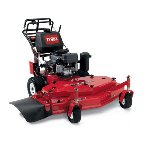
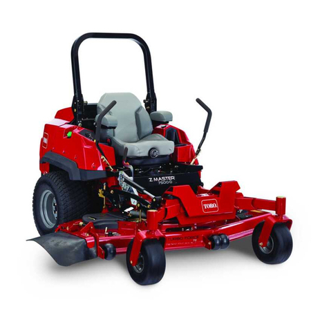
Toro Reelmaster 5410 User manual

FormNo.3424-342RevA
Reelmaster®5410and5510
TractionUnit
ModelNo.03675—SerialNo.403280001andUp
ModelNo.03676—SerialNo.403280001andUp
Registeratwww.Toro.com.
OriginalInstructions(EN)*3424-342*A

ThisproductcomplieswithallrelevantEuropean
directives;fordetails,pleaseseetheseparateproduct
specicDeclarationofConformity(DOC)sheet.
ItisaviolationofCaliforniaPublicResourceCode
Section4442or4443touseoroperatetheengineon
anyforest-covered,brush-covered,orgrass-covered
landunlesstheengineisequippedwithaspark
arrester,asdenedinSection4442,maintainedin
effectiveworkingorderortheengineisconstructed,
equipped,andmaintainedforthepreventionofre.
Theenclosedengineowner’smanualissuppliedfor
informationregardingtheUSEnvironmentProtection
Agency(EPA)andtheCaliforniaEmissionControl
Regulationofemissionsystems,maintenance,and
warranty.Replacementmaybeorderedthroughthe
enginemanufacturer.
WARNING
CALIFORNIA
Proposition65Warning
Dieselengineexhaustandsomeofits
constituentsareknowntotheStateof
Californiatocausecancer,birthdefects,
andotherreproductiveharm.
Batteryposts,terminals,andrelated
accessoriescontainleadandlead
compounds,chemicalsknownto
theStateofCaliforniatocause
cancerandreproductiveharm.Wash
handsafterhandling.
Useofthisproductmaycauseexposure
tochemicalsknowntotheStateof
Californiatocausecancer,birthdefects,
orotherreproductiveharm.
Introduction
Thismachineisaride-on,reel-bladelawnmower
intendedtobeusedbyprofessional,hiredoperators
incommercialapplications.Itisprimarilydesignedfor
cuttinggrassonwell-maintainedturf.
Readthisinformationcarefullytolearnhowtooperate
andmaintainyourproductproperlyandtoavoid
injuryandproductdamage.Youareresponsiblefor
operatingtheproductproperlyandsafely.
Visitwww.T oro.comformoreinformation,including
safetytips,trainingmaterials,accessoryinformation,
helpndingadealer,ortoregisteryourproduct.
Wheneveryouneedservice,genuineToroparts,or
additionalinformation,contactanAuthorizedService
DealerorToroCustomerServiceandhavethemodel
andserialnumbersofyourproductready.Figure2
identiesthelocationofthemodelandserialnumbers
ontheproduct.Writethenumbersinthespace
provided.
Important:Withyourmobiledevice,youcan
scantheQRcodeontheserialnumberplate(if
equipped)toaccesswarranty,parts,andother
productinformation.
g266613
Figure1
1.Modelandserialnumberlocation
ModelNo.
SerialNo.
Thismanualidentiespotentialhazardsandhas
safetymessagesidentiedbythesafety-alertsymbol
(Figure2),whichsignalsahazardthatmaycause
seriousinjuryordeathifyoudonotfollowthe
recommendedprecautions.
g000502
Figure2
1.Safety-alertsymbol
Thismanualuses2wordstohighlightinformation.
Importantcallsattentiontospecialmechanical
informationandNoteemphasizesgeneralinformation
worthyofspecialattention.
©2018—TheToro®Company
8111LyndaleAvenueSouth
Bloomington,MN554202
Contactusatwww.Toro.com.
PrintedintheUSA
AllRightsReserved

Contents
Safety.......................................................................4
GeneralSafety...................................................4
SafetyandInstructionalDecals..........................5
Setup......................................................................10
1AdjustingtheTirePressure............................10
2AdjustingtheControl-ArmPosition..................11
3InstallingtheCuttingUnits...............................11
4AdjustingtheTurf-Compensation
Spring...........................................................14
5InstallingtheCEHoodLatch..........................15
6UsingtheCutting-UnitKickstand....................15
ProductOverview...................................................16
Controls...........................................................16
Specications..................................................23
Attachments/Accessories.................................23
BeforeOperation.................................................24
BeforeOperationSafety...................................24
PerformingDailyMaintenance..........................24
FillingtheFuelTank..........................................24
DuringOperation.................................................25
DuringOperationSafety...................................25
StartingandStoppingtheEngine......................27
AdjustingtheLift-ArmCounterbalance.............27
AdjustingtheLift-ArmTurnaround
Position.........................................................27
SettingtheReelSpeed.....................................28
UnderstandingtheDiagnosticLight..................29
CheckingtheInterlockSwitches.......................29
HydraulicValveSolenoidFunctions..................30
OperatingTips.................................................30
AfterOperation....................................................31
AfterOperationSafety......................................31
PushingorTowingtheMachine........................31
LocatingtheJackingPoints..............................32
Maintenance...........................................................33
MaintenanceSafety..........................................33
RecommendedMaintenanceSchedule(s)...........33
DailyMaintenanceChecklist.............................35
Lubrication..........................................................36
GreasingtheBearingsandBushings................36
EngineMaintenance...........................................37
EngineSafety...................................................37
CheckingtheEngine-OilLevel..........................37
ServicingtheAirCleaner..................................38
ServicingtheEngineOilandFilter....................39
AdjustingtheThrottle........................................40
FuelSystemMaintenance...................................40
DrainingtheFuelT ank......................................40
CheckingtheFuelLinesand
Connections..................................................40
ServicingtheWaterSeparator..........................40
CleaningtheFuelPick-upTubeScreen............41
BleedingtheFuelSystem.................................41
ElectricalSystemMaintenance...........................41
ElectricalSystemSafety...................................41
ServicingtheBattery.........................................41
Fuses................................................................42
DriveSystemMaintenance..................................42
CheckingtheT orqueoftheWheel
Nuts..............................................................42
AdjustingtheTractionDriveforNeutral.............42
AdjustingtheRearWheelT oe-in.......................43
CoolingSystemMaintenance..............................44
CoolingSystemSafety.....................................44
CheckingtheCoolingSystem...........................44
RemovingDebrisfromtheCooling
System..........................................................44
BrakeMaintenance.............................................46
AdjustingtheParkingBrakes............................46
AdjustingtheParking-BrakeLatch....................46
BeltMaintenance................................................47
TensioningtheAlternatorBelt...........................47
HydraulicSystemMaintenance...........................47
HydraulicSystemSafety...................................47
CheckingtheHydraulic-FluidLevel...................48
ChangingtheHydraulicFluid............................48
ReplacingtheHydraulicFilters.........................49
CheckingtheHydraulicLinesand
Hoses............................................................50
TestingthePressureintheHydraulic
Circuits..........................................................50
CuttingUnitSystemMaintenance........................51
BladeSafety.....................................................51
CheckingtheReel-to-BedknifeContact............51
BacklappingtheCuttingUnits...........................51
Storage...................................................................53
PreparingtheTractionUnit...............................53
PreparingtheEngine........................................53
3
Safety
Thismachinehasbeendesignedinaccordancewith
ENISO5395:2017(whenappropriatedecalsare
applied)andANSIB71.4-2017.
GeneralSafety
Thisproductiscapableofamputatinghandsandfeet
andofthrowingobjects.
Usingthisproductforpurposesotherthanitsintended
usecouldprovedangeroustoyouandbystanders.
•Readandunderstandthecontentsofthis
Operator’sManualbeforestartingtheengine.
•Useyourfullattentionwhileoperatingthe
machine.Donotengageinanyactivitythat
causesdistractions;otherwise,injuryorproperty
damagemayoccur.
•Donotputyourhandsorfeetnearmoving
componentsofthemachine.
•Donotoperatethemachinewithoutallguards
andothersafetyprotectivedevicesinplaceand
functioningproperlyonthemachine.
•Keepchildren,bystanders,andpetsoutofthe
operatingarea.Neverallowchildrentooperate
themachine.
•Alwaysshutofftheengine,removethekey(if
equipped),waitforallmovingpartstostop,
andallowthemachinetocoolbeforeadjusting,
servicing,cleaning,orstoringthemachine.
Improperlyusingormaintainingthismachinecan
resultininjury.Toreducethepotentialforinjury,
complywiththesesafetyinstructionsandalways
payattentiontothesafety-alertsymbol,which
meansCaution,Warning,orDanger—personalsafety
instruction.Failuretocomplywiththeseinstructions
mayresultinpersonalinjuryordeath.
4

SafetyandInstructionalDecals
Safetydecalsandinstructionsareeasilyvisibletotheoperatorandarelocatednearanyarea
ofpotentialdanger.Replaceanydecalthatisdamagedorlost.
decal133-8062
133-8062
decal93-6689
93-6689
1.Warning—donotcarrypassengers.
decal93-6696
93–6696
1.Storedenergyhazard—readtheOperator'sManual.
decal93-7272
93-7272
1.Cutting/dismembermenthazard;fan—stayawayfrom
movingparts.
decal106-6754
106-6754
1.Warning—donottouchthehotsurface.
2.Cutting/dismembermenthazard,fan;entanglementhazard,
belt—stayawayfrommovingparts.
decal106-6755
106-6755
1.Enginecoolantunder
pressure.
3.Warning—donottouchthe
hotsurface.
2.Explosionhazard—read
theOperator'sManual.
4.Warning—readthe
Operator'sManual.
decal110-0986
110-0986
1.Pressthebrakepedalandparkingbrakepedaltosetthe
parkingbrake.
2.Pressthebrakepedaltoapplythebrake.
3.Pressthetractionpedaltomovethemachineforward.
4.Reelenabledmode
5.Transportmode
decal110-8921
110-8921
1.Tractionunitspeed
2.Slow
3.Fast
5

decal110-9642
110-9642
1.Storedenergyhazard—readtheOperator'sManual.
2.Movethecotterpintotheholeclosesttotherodbracket
andthenremovetheliftarmandpivotyoke.
r:\decal117-0169
117-0169
1.ReadtheOperator'sManual.
2.Lighter
3.Headlights
4.Electric
5.Enginestart
6.Airrideseatsuspension(optional)
7.EnginecomputermanagementC
8.EnginecomputermanagementB
9.EnginecomputermanagementA
decal120-4158
120–4158
1.ReadtheOperator’s
Manual.
3.Engine—preheat
2.Engine—start4.Engine—stop
decalbatterysymbols
BatterySymbols
Someorallofthesesymbolsareonyourbattery
1.Explosionhazard6.Keepbystandersasafe
distancefromthebattery.
2.Nore,opename,or
smoking.
7.Weareyeprotection;
explosivegasescan
causeblindnessandother
injuries
3.Causticliquid/chemical
burnhazard
8.Batteryacidcancause
blindnessorsevereburns.
4.Weareyeprotection9.Flusheyesimmediately
withwaterandgetmedical
helpfast.
5.ReadtheOperator's
Manual.
10.Containslead;donot
discard.
6

decal121-5644
121–5644
1.Lightswitch6.Slow
2.Engage7.Lower
3.Powertake-off8.Raise
4.Disengage9.ReadtheOperator’s
Manual.
5.Fast
7

decal133-2930
133-2930
1.Warning—donotoperatethismachineunlessyouaretrained.4.Tippinghazard—driveslowlywhenturning;donotturnsharply
whiletravelingfast;onlydriveonslopeswiththecuttingunits
lowered;alwayswearaseatbelt.
2.Warning—wearhearingprotection.5.Warning—donotparkonslopes;engagetheparkingbrake,
lowerthecuttingunits,shutofftheengine,andremovethe
ignitionkeybeforeleavingthemachine.
3.Thrownobjecthazard—keepbystandersaway.6.Warning—readtheOperator'sManual;donottowthe
machine.
decal133-2931
133-2931
Note:Thismachinecomplieswiththeindustrystandardstabilitytestinthestaticlateralandlongitudinaltestswiththemaximum
recommendedslopeindicatedonthedecal.ReviewtheinstructionsforoperatingthemachineonslopesintheOperator’sManualas
wellastheconditionsinwhichyouwouldoperatethemachinetodeterminewhetheryoucanoperatethemachineintheconditions
onthatdayandatthatsite.Changesintheterraincanresultinachangeinslopeoperationforthemachine.Ifpossible,keepthe
cuttingunitsloweredtothegroundwhileoperatingthemachineonslopes.Raisingthecuttingunitswhileoperatingonslopescan
causethemachinetobecomeunstable.
1.Warning—readtheOperator'sManual;donotoperatethis
machineunlessyouaretrained.
4.Tippinghazard—donotdriveacrossordownslopesgreater
than15°;onlydriveonslopeswiththecuttingunitslowered;
alwayswearaseatbelt.
2.Warning—wearhearingprotection.5.Warning—donotparkonslopes;engagetheparkingbrake,
lowerthecuttingunits,shutofftheengine,andremovethe
ignitionkeybeforeleavingthemachine.
3.Thrownobjecthazard—keepbystandersaway.6.Warning—readtheOperator'sManual;donottowthe
machine.
8

decal125-8753
125-8753
1.ReadtheOperator'sManualformoremaintenanceinformation.
9

Setup
LooseParts
Usethechartbelowtoverifythatallpartshavebeenshipped.
ProcedureDescriptionQty.Use
1Nopartsrequired–Adjustthetirepressure.
2Nopartsrequired–Adjustthecontrol-armposition.
Rightfronthoseguide1
3Leftfronthoseguide1Installthecuttingunits.
4Nopartsrequired–Adjusttheturf-compensationspring.
Hoodlatchassembly1
5Washer1InstalltheCEhoodlatch.
6Cutting-unitkickstand1Installthecutting-unitkickstand.
MediaandAdditionalParts
DescriptionQty.Use
Operator'sManual1
EngineOperator’sManual1Readthemanualsbeforeoperatingthemachine.
DeclarationofConformity1Thisdocumentindicatesconformitywithcertainstandards.
Operatortrainingmaterial1Reviewthetrainingmaterialbeforeoperatingthemachine.
Note:Determinetheleftandrightsidesofthe
machinefromthenormaloperatingposition.
1
AdjustingtheTirePressure
NoPartsRequired
Procedure
Thetiresareover-inatedforshipping.Therefore,
releasesomeoftheairtoreducethepressure.
Correctairpressureinthefrontandreartiresis83
to103kPa(12to15psi).
Important:Maintainevenpressureinalltiresto
ensurethatthereisuniformcontactwiththeturf.
10

2
AdjustingtheControl-Arm
Position
NoPartsRequired
Procedure
Thecontrol-armpositioncanbeadjustedforthe
operatorscomfort.
1.Loosenthe2boltssecuringthecontrolarmto
theretainingbracket(Figure3).
g004152
Figure3
1.Controlarm3.Bolts
2.Retainingbrackets
2.Rotatethecontrolarmtothedesiredposition
andtightenthe2bolts.
3
InstallingtheCuttingUnits
Partsneededforthisprocedure:
1Rightfronthoseguide
1Leftfronthoseguide
Procedure
1.Removethereelmotorsfromtheshipping
brackets.
2.Removetheshippingbracketsanddiscard.
3.Removethecuttingunitsfromthecartons.
Assembleandadjustasdescribedinthecutting
unitOperator'sManual.
4.Makesurethecounterweight(Figure4)is
installedtotheproperendofthecuttingunitas
describedinthecuttingunitOperator'sManual.
g003320
Figure4
1.Counterweight
5.Mounttheturf-compensationspringtothesame
sideofthecuttingunitasthereel-drivemotor.
Repositiontheturf-compensationspringas
follows:
Note:Allcuttingunitsareshippedwiththe
turf-compensationspringmountedtotheright
sideofthecuttingunit.
A.Removethe2carriageboltsandnuts
securingtherodbrackettothecutting-unit
tabs(Figure5).
11

g003949
Figure5
1.Turf-compensationspring3.Springtube
2.Rodbracket
B.Removetheangenutsecuringthe
spring-tubebolttothecarrier-frametab
(Figure5)Removetheassembly.
C.Mountthespring-tubebolttotheopposite
tabonthecarrierframeandsecurewiththe
angenut.Theboltheadistobepositioned
totheoutersideofthetabasshownin
Figure6.
g003967
Figure6
1.Oppositecarrier-frametab2.Rodbracket
D.Mounttherodbrackettothecutting-unit
tabswiththecarriageboltsandnuts(Figure
6).
Important:Onthe#4(leftfront)and
#5(rightfront)cuttingunits(Figure7),
usetherod-bracketmountingnutsto
installthehoseguidestothefrontofthe
cutting-unittabs(Figure8).Thehose
guidesshouldleantowardthecenter
cuttingunit(Figure8andFigure9).
g014684
Figure7
g015160
Figure8
1.Hoseguide(cuttingunit4
shown)
3.Nut
2.Rodbracket
g019284
Figure9
1.Hoseguidesmustleantowardthecentercuttingunit.
12

Note:Wheninstallingorremovingthe
cuttingunits,makesurethehairpincotteris
installedinthespringrodholenexttothe
rodbracket.Otherwise,thehairpincotter
mustbeinstalledintheholeintheendof
therod.
6.Lowerallliftarmscompletely.
7.Removethesnapperpinandthecapfromthe
lift-armpivotyoke(Figure10).
g003975
Figure10
1.Snapperpin2.Cap
8.Forthefrontcuttingunits,slideacuttingunit
undertheliftarmwhileinsertingthecarrier-frame
shaftupintothelift-arm-pivotyoke(Figure11).
g003977
Figure11
1.Liftarm3.Lift-arm-pivotyoke
2.Carrier-frameshaft
9.Usethefollowingprocedureontherearcutting
unitswhentheheightofcutisabove19mm
(3/4inch).
A.Removethelynchpinandwashersecuring
thelift-arm-pivotshafttotheliftarmand
slidethelift-arm-pivotshaftoutofthelift
arm(Figure12).
g003979
Figure12
1.Lynchpinandwasher
B.Insertthelift-armyokeontothecarrier-frame
shaft(Figure11).
C.Insertthelift-armshaftintotheliftarmand
secureitwiththewasherandlynchpin
(Figure12).
10.Insertthecapoverthecarrier-frameshaftand
lift-armyoke.
11.Securethecapandthecarrier-frameshafttothe
lift-armyokewiththesnapperpin(Figure10).
Note:Usetheslotifasteeringcuttingunitis
desiredorusetheholeifthecuttingunitisto
belockedinposition.
12.Securethelift-armchaintothechainbracket
withthesnapperpin(Figure13).
Note:Usethenumberofchainlinksdescribed
inthecuttingunitOperator'sManual.
g003948
Figure13
1.Lift-armchain3.Snapperpin
2.Chainbracket
13.Oncuttingunit4(leftfront)andcuttingunit5
(rightfront),insertthereel-motorhosesintothe
respectivehoseguide.
14.Coatthesplineshaftofthereelmotorwithclean
grease.
15.OilthereelmotorO-ringandinstallitontothe
motorange.
13

16.Installthemotorbyrotatingitclockwisesothat
themotorangesclearthebolts(Figure14).
Note:Rotatethemotorcounterclockwiseuntil
theangesencircletheboltsthentightenthe
bolts.
Important:Makesurethatthereel-motor
hosesarenottwisted,kinkedorintherisk
ofbeingpinched.
g004127
Figure14
1.Reel-drivemotor2.Mountingbolts
4
Adjustingthe
Turf-CompensationSpring
NoPartsRequired
Procedure
Theturf-compensationspring(Figure15)transfers
weightfromthefronttotherearroller.Thishelps
toreduceawavepatternintheturf,alsoknownas
marcellingorbobbing.
Important:Makespringadjustmentswiththe
cuttingunitmountedtothetractionunit,pointing
straightaheadandloweredtotheground.
1.Makesurethehairpincotterisinstalledinthe
rearholeinthespringrod(Figure15).
g003863
Figure15
1.Turf-compensationspring3.Springrod
2.Hairpincotter4.Hexnuts
2.Tightenthehexnutsonthefrontendofthe
springroduntilthecompressedlengthofthe
springis12.7cm(5inches)onReelmaster5410
(5-inchcuttingunits)or15.9cm(6.25inches)
onReelmaster5510(7-inchcuttingunits);refer
toFigure15.
Note:Whenoperatingonroughterrain,
decreasethespringlengthby12.7mm(1/2
inch).Thisslightlydecreasestheground
following.
14

5
InstallingtheCEHood
Latch
Partsneededforthisprocedure:
1Hoodlatchassembly
1Washer
Procedure
1.Unlatchandraisethehood.
2.Removetherubbergrommetfromtheholein
theleftsideofthehood(Figure16).
g004143
Figure16
1.Rubbergrommet
3.Removethenutfromthehoodlatchassembly
(Figure17).
g003946
Figure17
1.Hoodlatch3.Rubberwasher
2.Nut4.Metalwasher
4.Outsidethehood,insertthehookendofthe
latchthroughtheholeinthehood.Makesure
thattherubbersealingwasherremainstothe
outersideofthehood(Figure17).
5.Insidethehood,insertthemetalwasheronto
thelatchandsecurewiththenut.Makesure
thatthelatchengagestheframecatchwhenit
islocked.Usetheenclosedhoodlatchkeyto
operatethehoodlatch.
6
UsingtheCutting-Unit
Kickstand
Partsneededforthisprocedure:
1Cutting-unitkickstand
Procedure
Wheneverthecuttingunithastobetippedtoexpose
thebedknife/reel,propuptherearofthecuttingunit
withthekickstandtomakesurethatthenutsonthe
backendofthebedbar-adjustingscrewsarenot
restingontheworksurface(Figure18).
g003985
Figure18
1.Cutting-unitkickstand
Securethekickstandtothechainbracketwiththe
snapperpin(Figure19).
15

g004144
Figure19
1.Chainbracket3.Cutting-unitkickstand
2.Snapperpin
ProductOverview
g003945
Figure20
1.Enginehood5.Seatadjustments
2.Operator'sseat6.Frontcuttingunits
3.Controlarm7.Rearcuttingunits
4.Steeringwheel
Controls
Seat-AdjustingKnobs
Theseat-adjustinglever(Figure21)allowsyouto
adjusttheseatforeandaft.Theweight-adjusting
knobadjuststheseatfortheoperator'sweight.The
weightgaugeindicateswhentheseatisadjustedto
theweightoftheoperator.Theheight-adjustingknob
adjuststheseatfortheoperator'sheight.
g003954
Figure21
1.Weightgauge3.Height-adjustingknob
2.Weight-adjustingknob4.Adjustinglever(foreand
aft)
16

TractionPedal
Thetractionpedal(Figure22)controlstheforward
andreverseoperation.Pressthetopofthepedalto
movethemachineforwardandthebottomtomove
themachinebackward.Groundspeeddependson
howfaryoupressthepedal.Fornoload,maximum
groundspeed,fullypressthepedalwhilethethrottle
isintheFASTposition.
Tostopthemachine,reducefootpressureonthe
tractionpedalandallowittoreturntothecenter
position.
g003955
Figure22
1.Tractionpedal4.Brakepedal
2.Mow/transportlever5.Parkingbrake
3.Mow-speedlimiterand
spacers
6.Tiltsteeringpedal
Mow/TransportLever
Usethemow/transportlever(Figure22)toputthe
machineintoMOWmodeorTRANSPORTmode.Push
theleverforwardtoselecttheMOWmode,and
backwardtoselecttheTRANSPORTmode.
Note:Thecuttingunitscannotbeloweredwhenthe
mow/transportleverisintheTRANSPORTposition.
Mow-SpeedLimiter
Whenthemow-speedlimiter(Figure22)isipped
up/forwarditlimitsthemowspeedandallowthe
cuttingunitstobeengaged.Eachspaceradjusts
themowingspeedby0.8km/h(0.5mph).Themore
spacersthereareonthetopofthebolt,theslowerthe
machinegoes.Flipthemowspeedlimiterbackward
toallowmaximumtransportspeed.
BrakePedal
Pressthebrakepedal(Figure22)tostopthemachine.
ParkingBrake
Toengagetheparkingbrake,(Figure22)pushdown
onthebrakepedalandpressthetopforwardtolatch
it.Toreleasetheparkingbrake,pressthebrakepedal
untiltheparking-brakelatchretracts.
Tilt-SteeringPedal
Totiltthesteeringwheeltowardsyou,pressthefoot
pedal(Figure22)down,pullthesteeringtowertoward
youtothemostcomfortableposition,andreleasethe
pedal.
ThrottleControl
Movethethrottlecontrol(Figure23)forwardto
increasetheenginespeedandrearwardtodecrease
speed.
g025902
Figure23
1.Lowermow/raisecontrol
lever
4.Enable/disableswitch
2.Keyswitch5.Throttlecontrol
3.InfoCenter6.Headlightswitch
KeySwitch
Thekeyswitch(Figure23)has3positions:OFF,
ON/PREHEAT,andSTART.
LowerMow/RaiseControlLever
Thislever(Figure23)raisesandlowersthecutting
unitsandalsostartsandstopsthecuttingunitswhen
thecuttingunitsareenabledintheMOWmode.You
cannotlowerthecuttingunitswhenthemow/transport
leverisintheTRANSPORTposition.
17

HeadlightSwitch
Pivottheswitchdownwardtoturnontheheadlights
(Figure23).
Enable/DisableSwitch
Usetheenable/disableswitch(Figure23)in
conjunctionwiththelowermow/raisecontrolleverto
operatethecuttingunits.
BacklapLevers
Usethebacklapleversinconjunctionwiththelower
mow/raisecontrolleverforbacklappingthereels
(Figure24).
g021209
Figure24
1.Backlaplevers
Hydraulic-FilterRestriction
Indicator
Withtheenginerunningatnormaloperating
temperature,ensurethattheindicatorisinthegreen
zone(Figure25).Whentheindicatorisinthered
zone,changethehydrauliclters.
g004132
Figure25
1.Hydraulic-lter-restrictionindicator
PowerPoint
Thepowerpointisa12Vpowersupplyforelectronic
devices(Figure26).
g004133
Figure26
1.Powerpoint
UsingtheInfoCenterLCDDisplay
TheInfoCenterLCDdisplayshowsinformationabout
yourmachinesuchastheoperatingstatus,various
diagnosticsandotherinformationaboutthemachine
(Figure27)Thereisasplashscreenandmain
informationscreenoftheInfoCenter.Youcanswitch
betweenthesplashscreenandmaininformation
screen,atanytime,bypressinganyoftheInfoCenter
buttonsandthenselectingtheappropriatedirectional
arrow.
18

g020650
Figure27
1.Indicatorlight3.Middlebutton
2.Rightbutton4.Leftbutton
•LeftButton,MenuAccess/BackButton—Press
thisbuttontoaccesstheInfoCentermenus.
Youcanuseittobackoutofanymenuyouare
currentlyusing.
•MiddleButton—Pressthisbuttontoscrolldown
menus.
•RightButton—Pressthisbuttontoopenamenu
wherearightarrowindicatesadditionalcontent.
Note:Thepurposeofeachbuttonmaychange
dependingonwhatisrequiredatthetime.Each
buttonislabeledwithanicondisplayingitscurrent
function.
InfoCenterIconDescription
SERVICEDUEIndicateswhenscheduledservice
shouldbeperformed
Hourmeter
Infoicon
Fast
Slow
Fuellevel
Theglowplugsareactive.
Raisethecuttingunits.
InfoCenterIconDescription(cont'd.)
Lowerthecuttingunits.
Sitintheseat.
TheparkingbrakeisOn.
Therangeishigh(transport).
Neutral
Therangeislow(mow).
Engine-coolanttemperature(°Cor
°F)
Temperature(hot)
ThePTOisengaged.
Notallowed
Starttheengine.
Stoptheengine.
Engine
Keyswitch
Thecuttingunitsarelowering.
Thecuttingunitsareraising.
PINpasscode
CANbus
InfoCenter
Badorfailed
Bulb
OutputofTECcontrollerorcontrol
wireinharness
Switch
19

InfoCenterIconDescription(cont'd.)
Releasetheswitch.
Changetotheindicatedstate.
Symbolsareoften
combinedtoform
sentences.Some
examplesareshown
below
PutthemachineintoNeutral.
Enginestartisdenied.
Engineshutdown
Enginecoolantistoohot.
Sitdownorsettheparkingbrake
20
This manual suits for next models
1
Table of contents
Other Toro Lawn Mower manuals

Toro
Toro 74657 User manual

Toro
Toro 02750 User manual

Toro
Toro Z Master 4000 Series User manual

Toro
Toro Grandstand 78525 User manual

Toro
Toro Recycler 21469 User manual

Toro
Toro 74408TE User manual

Toro
Toro TimeCutter SS 5425 User manual

Toro
Toro TimeCutter SS 4200 74720 User manual

Toro
Toro 22195 User manual

Toro
Toro 73570 Manual