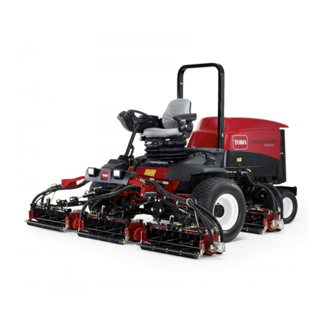
Toro REELMASTER 6700 D User manual

FormNo.3427-463RevA
Reelmaster®6700-D4-Wheel
DriveTractionUnit
ModelNo.03813—SerialNo.403190001andUp
Registeratwww.Toro.com.
OriginalInstructions(EN)*3427-463*A

ThisproductcomplieswithallrelevantEuropean
directives.Fordetails,pleaseseetheseparate
productspecicDeclarationofConformity(DOC)
sheet.
ItisaviolationofCaliforniaPublicResourceCode
Section4442or4443touseoroperatetheengineon
anyforest-covered,brush-covered,orgrass-covered
landunlesstheengineisequippedwithaspark
arrester,asdenedinSection4442,maintainedin
effectiveworkingorderortheengineisconstructed,
equipped,andmaintainedforthepreventionofre.
Theenclosedengineowner’smanualissupplied
forinformationregardingtheUSEnvironmental
ProtectionAgency(EPA)andtheCaliforniaEmission
ControlRegulationofemissionsystems,maintenance,
andwarranty.Replacementsmaybeorderedthrough
theenginemanufacturer.
WARNING
CALIFORNIA
Proposition65Warning
Dieselengineexhaustandsomeofits
constituentsareknowntotheStateof
Californiatocausecancer,birthdefects,
andotherreproductiveharm.
Batteryposts,terminals,andrelated
accessoriescontainleadandlead
compounds,chemicalsknownto
theStateofCaliforniatocause
cancerandreproductiveharm.Wash
handsafterhandling.
Useofthisproductmaycauseexposure
tochemicalsknowntotheStateof
Californiatocausecancer,birthdefects,
orotherreproductiveharm.
Introduction
Thismachineisaride-on,reel-bladelawnmower
intendedtobeusedbyprofessionaloperatorsin
commercialapplications.Itisprimarilydesigned
forcuttinggrassonwell-maintainedturf.Usingthis
productforpurposesotherthanitsintendedusecould
provedangeroustoyouandbystanders.
Readthisinformationcarefullytolearnhowtooperate
andmaintainyourproductproperlyandtoavoid
injuryandproductdamage.Youareresponsiblefor
operatingtheproductproperlyandsafely.
Visitwww.T oro.comformoreinformation,including
safetytips,trainingmaterials,accessoryinformation,
helpndingadealer,ortoregisteryourproduct.
Wheneveryouneedservice,genuineToroparts,or
additionalinformation,contactanAuthorizedService
DealerorT oroCustomerServiceandhavethemodel
andserialnumbersofyourproductready.Figure1
identiesthelocationofthemodelandserialnumbers
ontheproduct.Writethenumbersinthespace
provided.
Important:Withyourmobiledevice,youcan
scantheQRcode(ifequipped)ontheserial
numberdecaltoaccesswarranty,parts,andother
productinformation.
g273284
Figure1
1.Locationofthemodelandserialnumbers
ModelNo.
SerialNo.
Thismanualidentiespotentialhazardsandhas
safetymessagesidentiedbythesafety-alertsymbol
(Figure2),whichsignalsahazardthatmaycause
seriousinjuryordeathifyoudonotfollowthe
recommendedprecautions.
g000502
Figure2
Safety-alertsymbol
©2018—TheToro®Company
8111LyndaleAvenueSouth
Bloomington,MN554202
Contactusatwww.Toro.com.
PrintedintheUSA
AllRightsReserved

Thismanualuses2wordstohighlightinformation.
Importantcallsattentiontospecialmechanical
informationandNoteemphasizesgeneralinformation
worthyofspecialattention.
Contents
Safety.......................................................................4
GeneralSafety...................................................4
SafetyandInstructionalDecals..........................4
Setup.......................................................................11
1CheckingFluidLevels....................................12
2InstallingtheCuttingUnits..............................12
3MakingAlternateCuttingUnit
Adjustments..................................................17
4AddingRearBallast.......................................18
5ApplyingtheCEDecals.................................18
ProductOverview...................................................18
Controls...........................................................18
Specications..................................................21
Attachments/Accessories.................................21
BeforeOperation.................................................22
BeforeOperationSafety...................................22
PerformingDailyMaintenance..........................22
FillingtheFuelTank..........................................23
DuringOperation.................................................23
DuringOperationSafety...................................23
StartingtheEngine...........................................24
ShuttingOfftheEngine.....................................25
BleedingtheFuelSystem.................................25
CheckingtheInterlockSwitches.......................25
FaultMemoryandRetrieval..............................27
OperatingTips.................................................27
AfterOperation....................................................28
AfterOperationSafety......................................28
HaulingtheMachine.........................................28
IdentifyingtheTie-DownPoints........................28
PushingorTowingtheMachine........................29
HydraulicSolenoidValveFunctions..................29
Maintenance...........................................................30
MaintenanceSafety..........................................30
RecommendedMaintenanceSchedule(s)...........30
DailyMaintenanceChecklist.............................31
Lubrication..........................................................32
GreasingtheBearingsandBushings................32
EngineMaintenance...........................................34
EngineSafety...................................................34
ServicingtheAirCleaner..................................34
CheckingtheEngineOil...................................35
ServicingtheEngineOilandFilter....................36
AdjustingtheThrottle........................................37
FuelSystemMaintenance...................................38
DrainingtheFuelT ank......................................38
CheckingtheFuelLinesand
Connections..................................................38
ServicingtheWaterSeparator.........................38
BleedingAirfromtheInjectors..........................39
ElectricalSystemMaintenance...........................39
ElectricalSystemSafety...................................39
ServicingtheBattery.........................................39
CheckingtheFuses..........................................40
DriveSystemMaintenance..................................40
CheckingtheTirePressure...............................40
CheckingtheTorqueoftheWheelNutsand
Bolts..............................................................40
CheckingthePlanetaryGearDrive
Oil.................................................................40
ChangingthePlanetaryGearDrive
Oil.................................................................41
CheckingtheRearAxleLubricant.....................41
ChangingtheRearAxleLubricant....................42
CheckingtheRearWheelT oe-In......................42
AdjustingtheTractionDriveforNeutral.............42
CoolingSystemMaintenance..............................43
CoolingSystemSafety.....................................43
RemovingDebris..............................................43
CheckingtheCoolingSystem...........................44
MaintainingtheCoolingSystem........................44
BrakeMaintenance.............................................45
AdjustingtheServiceBrakes............................45
BeltMaintenance................................................46
CheckingtheAlternatorBelt.............................46
HydraulicSystemMaintenance...........................46
HydraulicSystemSafety...................................46
CheckingtheHydraulicFluid............................46
HydraulicFluidSpecications...........................47
HydraulicFluidCapacity...................................47
ChangingtheHydraulicFluid............................47
ReplacingtheHydraulicFilter...........................48
CheckingtheHydraulicLinesand
Hoses............................................................48
UsingtheHydraulicSystemT estPorts..............48
CuttingUnitSystemMaintenance........................50
BladeSafety.....................................................50
CheckingtheReel-to-BedknifeContact............50
BacklappingtheCuttingUnits...........................50
AdjustingtheCuttingUnitLowering
Rate..............................................................51
AdjustingtheLiftedHeightoftheOuterFront
CuttingUnits(EnablePosition)......................51
AdjustingtheTraveloftheFront3Cutting
Units..............................................................52
Storage...................................................................53
StorageSafety..................................................53
PreparingtheTractionUnit...............................53
PreparingtheEngine........................................53
3
Safety
Thismachinehasbeendesignedinaccordance
withENISO5395(whenyoucompletethesetup
procedures)andANSIB71.4-2017.
GeneralSafety
Thisproductiscapableofamputatinghandsandfeet
andofthrowingobjects.
•Readandunderstandthecontentsofthis
Operator’sManualbeforestartingtheengine.
•Useyourfullattentionwhileoperatingthe
machine.Donotengageinanyactivitythat
causesdistractions;otherwise,injuryorproperty
damagemayoccur.
•Donotputyourhandsorfeetnearmoving
componentsofthemachine.
•Donotoperatethemachinewithoutallguards
andothersafetyprotectivedevicesinplaceand
functioningproperlyonthemachine.
•Keepchildren,bystanders,andpetsoutofthe
operatingarea.Neverallowchildrentooperate
themachine.
•Shutofftheengine,removethekey,waitforall
movementtostopbeforeyouleavetheoperator’s
position.Allowthemachinetocoolbefore
adjusting,servicing,cleaning,orstoringit.
Improperlyusingormaintainingthismachinecan
resultininjury.T oreducethepotentialforinjury,
complywiththesesafetyinstructionsandalways
payattentiontothesafety-alertsymbol,which
meansCaution,Warning,orDanger—personalsafety
instruction.Failuretocomplywiththeseinstructions
mayresultinpersonalinjuryordeath.
SafetyandInstructionalDecals
Safetydecalsandinstructionsareeasilyvisibletotheoperatorandarelocatednearanyarea
ofpotentialdanger.Replaceanydecalthatisdamagedormissing.
93-1263
decal93-1263
93-1263
1.ReadtheOperator'sManual.
2.Toengagetheparkingbrake,connectthebrakepedals
withthelockingpin,pushdownonbothpedals,andpullthe
brakelatchout.
3.Toreleasetheparkingbrake,pressbothpedalsuntilthe
parkingbrakelatchretracts.
4.Danger—reelsenabled.
decal93-6668
93-6668
1.ReadtheOperator'sManualforinformationonchargingthe
battery;containslead;donotdiscard.
decal93-6681
93-6681
1.Cutting/dismembermenthazard,fan—stayawayfrom
movingparts.
4

decal93-6686
93-6686
1.Hydraulicuid2.ReadtheOperator's
Manual.
decal93-6687
93-6687
1.Donotstephere.
decal93-6689
93-6689
1.Warning—donotcarrypassengers.
decal93-6693
93-6693
1.Crushinghazardofhand—waitformovingpartstostop.
decal93-6696
93–6696
1.Storedenergyhazard—readtheOperator'sManual.
decal93-6699
93-6699
1.Machinespeed3.Continuousvariable
setting
2.Slow4.Fast
2
1
decal93-9425
93-9425
1.Warning—readtheOperator'sManual.
2.Highpressureuidhazard,injectionintothebody—stay
awayfrommovingparts;seekmedicalattention.
decal104-9298
104-9298
1.ReadtheOperator'sManual.
5

decal105-0123
105-0123
1.Throttle—slow7.Reelsdisabled—liftandlower
2.Throttle—fast8.Headlights
3.Reelsraisedandoff9.Headlights—On
4.Reelsloweredandonwhenenabled—forwardandbacklap10.Headlights—Off
5.Reels—enabled11.ReadtheOperatorsManual.
6.Reelsdisabled—liftonly
decal105-7506
105-7506
1.ReadtheOperator's
Manual.
4.Engine—preheat
2.Engine—stop5.Engine—start
3.On
decal106-6754
106-6754
1.Warning—donottouchthehotsurface.
2.Cutting/dismembermenthazard,fan;entanglementhazard,
belt—stayawayfrommovingparts.
decal106-6755
106-6755
1.Enginecoolantunder
pressure.
3.Warning—donottouchthe
hotsurface.
2.Explosionhazard—read
theOperator'sManual.
4.Warning—readthe
Operator'sManual.
6

decal115-2045
115-2045
1.Warning—readtheOperator'sManual.
2.Cuttinghazardofthefoot;cuttinghazardofthehand—stayawayfrommovingparts;keepallguardsandshieldsinplace.
3.Warning—donotoperatethismachineunlessyouaretrained.
4.Tippinghazard—lowerthecuttingunitwhendrivingdownslopes;driveslowlywhenturning;donotturnsharplywhiletravelingfast.
5.Warning—weartheseatbelt.
6.Warning—readtheOperator'sManual;donottowthemachine.
7.Thrownobjecthazard—keepbystandersaway.
8.Warning—engagetheparkingbrake,shutofftheengine,andremovethekeybeforeleavingthemachine.
7

decal115-2046
115-2046
Note:Thismachinecomplieswiththeindustrystandardstabilitytestinthestaticlateralandlongitudinaltestswiththemaximum
recommendedslopeindicatedonthedecal.ReviewtheinstructionsforoperatingthemachineonslopesintheOperator’sManualas
wellastheconditionsinwhichyouwouldoperatethemachinetodeterminewhetheryoucanoperatethemachineintheconditions
onthatdayandatthatsite.Changesintheterraincanresultinachangeinslopeoperationforthemachine.Ifpossible,keepthe
cuttingunitsloweredtothegroundwhileoperatingthemachineonslopes.Raisingthecuttingunitswhileoperatingonslopescan
causethemachinetobecomeunstable.
1.Warning—readtheOperator'sManual.
2.Cuttinghazardofthefoot;cuttinghazardofthehand—stayawayfrommovingparts;keepallguardsandshieldsinplace.
3.Warning—donotoperatethismachineunlessyouaretrained.
4.Tippinghazard—lowerthecuttingunitwhendrivingdownslopes;donotmowonslopesgreaterthan15°.
5.Warning—weartheseatbelt.
6.Warning—readtheOperator'sManual;donottowthemachine.
7.Thrownobjecthazard—keepbystandersaway.
8.Warning—engagetheparkingbrake,shutofftheengine,andremovethekeybeforeleavingthemachine.
decal115-2047
115-2047
1.Warning—donottouchthehotsurface.
8

decal115-8000
115-8000
1.Heightofcut4.Machinespeed
2.Reel—mowandbacklap5.Rearreelscircuitcontrols
3.ReadtheOperator's
Manual.
6.Frontreelscircuitcontrols
decal133-8062
133-8062
decal138-6982
138-6982
1.ReadtheOperator'sManual.
9

decalbatterysymbols
BatterySymbols
Someorallofthesesymbolsareonyourbattery
1.Explosionhazard6.Keepbystandersasafe
distancefromthebattery.
2.Nore,opename,or
smoking
7.Weareyeprotection;
explosivegasescan
causeblindnessandother
injuries.
3.Causticliquid/chemical
burnhazard
8.Batteryacidcancause
blindnessorsevereburns.
4.Weareyeprotection9.Flusheyesimmediately
withwaterandgetmedical
helpfast.
5.ReadtheOperator's
Manual.
10.Containslead;donot
discard.
10

Setup
LooseParts
Usethechartbelowtoverifythatallpartshavebeenshipped.
ProcedureDescriptionQty.Use
1Nopartsrequired–Checktheuidlevels.
Liftchain7
Chainbracket7
U-bolt7
Nut14
Screw7
Washer7
Nut7
LargeO-ring7
2
Kickstand1
Installthecuttingunits.
3Nopartsrequired–Makecuttingunitadjustmentsifneeded.
Calciumchloride(obtainseparately)45kg
(100lb)
4Rearweightkit,partnumber104-1478
(obtainseparately)1
Addrearballast(ifrequired).
Warningdecal1
CEdecal1
5Yearofproductiondecal1
ApplytheCEdecals.
MediaandAdditionalParts
DescriptionQty.Use
Operator'sManual1Readthemanualbeforeoperatingthemachine.
Engineowner'smanual1Readthemanualbeforeoperatingtheengine.
DeclarationofConformity1ThisdocumentindicatesCEcompliance.
DiagnosticACEdisplayoverlay1ThediagnosticACEdisplayoverlayisfordiagnosing
machinemalfunctions.
Key2Usethekeystostartthemachine.
Hoodlockkey1Usethehoodlockkeytolockandunlockthehood.
Note:Determinetheleftandrightsidesofthemachinefromthenormaloperatingposition.
11

1
CheckingFluidLevels
NoPartsRequired
Procedure
Beforestartingtheengineforthersttime,checkthe
followinguidlevels:
•Engineoil
RefertoCheckingtheEngineOil(page35).
•Enginecoolant
RefertoCheckingtheCoolingSystem(page44).
•Hydraulicoil
RefertoCheckingtheHydraulicFluid(page46).
•Rearaxlelubricant
RefertoCheckingtheRearAxleLubricant(page
41).
2
InstallingtheCuttingUnits
Partsneededforthisprocedure:
7Liftchain
7Chainbracket
7U-bolt
14Nut
7Screw
7Washer
7Nut
7LargeO-ring
1Kickstand
RemovingtheTipperAssemblies
Removethetipperassemblies(ifsoequipped)from
thenumber1,number2,andnumber3liftarms
toavoidinterferencewiththecarrierframesofthe
cuttingunits.
1.Removethelocknutandthewashersecuring
thepivotrodtothenumber2liftarm(Figure
3).Removethepivotrodandspringfromthe
liftarm.Repeattheprocedureonthenumber1
andnumber3liftarms.
12

g006533
Figure3
1.Pivotrod2.Tippersupportbracket
w/roller
Note:Thetipperbracketwiththerollerandthe
tippersupportbracketsarenotrequiredwhen
operatingtheDPAcuttingunits(Figure3).
2.Disconnecttheliftchainsfromthecuttingunits,
ifattached.
MountingtheLiftBracketsand
Chains
MountachainbrackettoeachliftarmwithaU-bolt
and2nuts.Positionthebracketsasfollows:
Note:RefertoFigure4todeterminetheliftarm
numberbeingdescribed.
g034112
Figure4
1.Cuttingunit16.Cuttingunit6
2.Cuttingunit27.Cuttingunit7
3.Cuttingunit38.Reelmotor
4.Cuttingunit49.Weight
5.Cuttingunit5
1.Onliftarmnumbers1,4,and5,positionthe
chainbracketsandU-bolts38.1cm(15inches)
behindthecenterlineofthepivotknuckle
(Figure5).
2.Onliftarmnumbers1and5thebracketsshould
berotatedtotheright10degreesfromvertical
(Figure5).
3.Onliftarmnumber4thebracketshouldbe
rotatedtotheleft10degreesfromvertical
(Figure5).
g020546
Figure5
1.Liftarmnumber5=
38.1cm(15inches)
3.Liftarmnumbers1and5=
10degrees
2.Liftarmnumber4=
10degrees
4.Onliftarmnumbers2and3,positionthe
bracketsandU-bolts38.1cm(15inches)behind
thecenterlineofthepivotknuckle(Figure6).
Note:Rotatethebrackets45degreestothe
outboardsideofthemachine.
13

g020547
Figure6
1.Liftarmnumber
2=38.1cm
(15inches)
2.Liftarmnumber3=
45degrees
5.Onliftarmnumber6andnumber7,position
thebracketsandU-bolts36.8cm(14.5inches)
behindthecenterlineofthepivotknuckle
(Figure7).
Note:Rotatethebrackets10degreestothe
outboardsideofthemachine.
g020548
Figure7
1.Liftarmnumber
6=36.8cm
(14.5inches)
2.Liftarmnumber7=
10degrees
6.TightenalltheU-boltnutsto52to65N∙m(38
to48ft-lb).
7.Mountaliftchaintoeachchainbracketwitha
screw,awasher,andanut,positioningthemas
showninFigure8.
g006540
Figure8
1.Liftchain2.Chainbracket
UsingtheKickstand
Wheneverthecuttingunithastobetippedtoexpose
thebedknife/reel,propuptherearofthecuttingunit
withthekickstandtomakesurethatthenutsonthe
backendofthebedbaradjustingscrewsarenot
restingontheworksurface(Figure9).
g003318
Figure9
1.Kickstand
14

AdjustingtheRearShield
Undermostconditions,bestdispersionisattained
whentherearshieldisclosed(frontdischarge).When
conditionsareheavyorwet,therearshieldmaybe
opened.
Toopentherearshield(Figure10),loosenthecap
screwsecuringtheshieldtotheleftsideplate,rotate
theshieldtotheopenposition,andtightenthecap
screw.
g003316
Figure10
1.Rearshield2.Capscrew
MountingtheCounterweights
Allcuttingunitsareshippedwiththecounterweight
mountedtotheleftendofthecuttingunit.Usethe
followingdiagramtodeterminethepositionofthe
counterweightsandreelmotors.
Note:Sometractionunitshaveonly5cuttingunits.
g034112
Figure11
1.Cuttingunit16.Cuttingunit6
2.Cuttingunit27.Cuttingunit7
3.Cuttingunit38.Reelmotor
4.Cuttingunit49.Weight
5.Cuttingunit5
1.Oncuttingunitnumbers2,4,and6,removethe
2capscrewssecuringthecounterweighttothe
leftendofthecuttingunit.
Note:Removethecounterweight(Figure12).
g003320
Figure12
1.Counterweight
2.Ontherightendofthecuttingunit,removethe
plasticplugfromthebearinghousing(Figure
13).
3.Removethe2capscrewsfromtherightside
plate(Figure13).
g003321
Figure13
1.Plasticplug2.Capscrew(2)
4.Installthecounterweighttotherightendof
thecuttingunitwiththe2screwspreviously
removed.
5.Looselyinstallthe2reelmotormountingcap
screwstotheleftsideplateofthecuttingunit
(Figure13).
15

InstallingtheCuttingUnits
Figure14showstheorientationofthehydraulicdrive
motorforeachofthecuttingunitlocations.Forany
ofthelocationsrequiringthemotortobemounted
ontherightendofthecuttingunit,installacounter
weightontheleftendofthecuttingunit.Forthe
locationsrequiringthemotortobemountedonthe
leftend,installacounterweightontherightendof
thecuttingunit.
Note:Thecounterweightmountingcapscrewsare
shippedinstalledontherightbearinghousingofthe
cuttingunits.Thecapscrewsontheleftbearing
housingaretobeusedforsecuringthehydraulic
motor.
g034112
Figure14
1.Cuttingunit16.Cuttingunit6
2.Cuttingunit27.Cuttingunit7
3.Cuttingunit38.Reelmotor
4.Cuttingunit49.Weight
5.Cuttingunit5
1.Removethecuttingunitsfromthecartons.
Assembleandadjustthemperthecuttingunit
Operator'sManual.
2.Removetheprotectiveplugsfromeachendof
thecuttingunit.
3.LubricateandinstallalargeO-ringintobearing
housinggrooveoneachendofcuttingunit
(Figure15&Figure18).
g000742
Figure15
1.Bearinghousing3.Counterweight
2.Largeo-ring
Note:Beforeinstallingthecuttingunitmotors
orcounterweights,lubricatetheinternalsplines
ofthecuttingunitreelshaftswithgrease.
4.Installacounterweightontotheappropriateend
ofeachcuttingunitwiththecapscrewsprovided
(Figure15).
5.Thoroughlygreasethecuttingunitreelbearings
priortoinstallationonthetractionunit.Grease
shouldbeevidentattheinboardreelseals;
refertothecuttingunitOperator'sManualfor
greasingprocedure.
6.Insertathrustwasherontothehorizontalshaft
ofthepivotknuckleasshownin(Figure16).
g000749
Figure16
1.Carrierframe4.Lynchpin
2.Pivotknuckle5.Steeringlockingpin
3.Liftarmsteeringplate
7.Insertthehorizontalshaftofthepivotknuckle
intothemountingtubeofthecarrierframe
(Figure16).
8.Securethepivotknuckletothecarrierframewith
athrustwasher,aatwasher,andaange-head
capscrew(Figure16).
9.Insertathrustwasherontoverticalshaftofpivot
knuckle(Figure16).
10.Ifremoved,inserttheverticalshaftofthepivot
knuckleintoliftarmpivothub(Figure16).Guide
thepivotknuckleinplacebetweenthetwo
rubbercenteringbumpersintheundersideof
theliftarmsteeringplate.
11.Insertthelynchpinintothecrossholeonthe
pivotknuckleshaft(Figure16).
12.Removenutsecuringturfcompensationspring
mountingbrackettocuttingunitstabilizerear
(Figure17).Installthetipperchainontothe
capscrewandsecureitwiththenutthatyou
previouslyremoved.
16

g000758
Figure17
1.Liftchain2.Cuttingunitstabilizerear
13.Mountthemotortothedriveendofthecutting
unitandsecureitwith2capscrews(Figure18).
g000769
Figure18
1.Motor2.O-ring
Note:Ifxedcuttingunitpositionisrequired,
insertthesteeringlockingpinintothepivot
knucklemountinghole(Figure16).
14.Hookthespringwirearoundthebottomofthe
steeringlockingpin(Figure16).
Turf-CompensationSettings
Theturf-compensationspringtransferstheweight
fromthefronttotherearroller.Thishelpstoreduce
awavepatternintheturf,alsoknownasmarcelling
orbobbing.
Important:Makespringadjustmentswiththe
cuttingunitmountedtothetractionunit,pointing
straightaheadandloweredtotheshopoor.
1.Makesurethatthehairpincotterisinstalledin
therearholeinthespringrod(Figure19).
g003863
Figure19
1.Turf-compensationspring3.Springrod
2.Hairpincotter4.Hexnuts
2.Tightenthehexnutsonthefrontendofthe
springroduntilthecompressedlengthofthe
springis15.9cm(6.25inches);refertoFigure
19.
Note:Whenoperatingonroughterrain
decreasethespringlengthby12.7mm(0.5
inch).Groundfollowingwillbeslightlyshorter.
Note:Youmustresettheturf-compensation
settingiftheHOCsettingorthe
aggressiveness-of-cutsettingischanged.
3
MakingAlternateCutting
UnitAdjustments
NoPartsRequired
Procedure
Thefactorysetsthetractorappropriatelyformost
fairwaymowingapplications.Severaladjustments
forne-tuningthemachineforparticularapplications
areincludedintheCuttingUnitMaintenancesection
asfollows:
•Adjustingthecuttingunitloweringrate
Adjuststhespeedatwhichthecuttingunitslower.
•Adjustingtheliftedheightoftheouterfrontcutting
units
Adjuststheturnaroundheightoftheouterfront
cuttingunitstoprovidegreaterclearanceon
contouredfairways.
•Adjustingthetravelofthefrontthreecuttingunits
17

Adjuststhedownwardtravelofthefrontthree
cuttingunitstoallowforhighlycontouredfairways.
4
AddingRearBallast
Partsneededforthisprocedure:
45kg
(100
lb)
Calciumchloride(obtainseparately)
1Rearweightkit,partnumber104-1478(obtain
separately)
Procedure
TocomplywithENISO5395andANSIB71.4-2017,
add45kg(100lb)ofcalciumchlorideballast
totherearwheelsandinstalltherearweightkit
(PartNo.104-1478).
Important:Ifapunctureoccursinatirewith
calciumchloride,removethemachinefromthe
turfareaasquicklyaspossible.Toprevent
possibledamagetoturf,immediatelysoakthe
affectedareawithwater.
5
ApplyingtheCEDecals
Partsneededforthisprocedure:
1Warningdecal
1CEdecal
1Yearofproductiondecal
Procedure
OnmachinesrequiringCEcompliance,applytheyear
ofproductiondecal(PartNo.133-5615)nearthe
serialplate,theCEdecal(PartNo.93-7252)near
thehoodlock,andtheCEwarningdecal(PartNo.
115-2046)overthestandardwarningdecal(PartNo.
115-2045).
ProductOverview
Controls
TractionPedal
Thetractionpedal(Figure20)controlsforwardand
reverseoperation.Pressthetopofthepedalto
movethemachineforwardandthebottomofthe
pedaltomovethemachinebackward.Groundspeed
isdeterminedbyhowfaryoupressthepedal.For
maximumgroundspeed,fullypressthepedalwhile
thethrottleisintheFASTposition.
Tostopthemachine,reduceyourfootpressureon
thetractionpedalandallowittoreturntothecenter
position.
g019447
Figure20
1.Tractionpedal6.Parkingbrakelatch
2.Forwardspeedlimiter7.Lockingpin
3.Reddiagnosticlight8.Reversespeedlimiter
4.Speedometer9.Keyswitch
5.Brakepedals
ForwardSpeedLimiter
Presettheforwardspeedlimiter(Figure20)tolimit
theamountthetractionpedalcanbepressedinthe
forwarddirectiontomaintainaconstantmowing
speed.
RedDiagnosticLight
Thereddiagnosticlight(Figure20),locatedon
steeringtower,isusedtoconveyseveraldifferent
messages.Whilestartingthemachine,thelight
illuminateswhentheglowplugsareon.
18

Ifthelightblinksduringoperation,itmayindicateany
ofthefollowing:
•Themachineisbeingoperatedfasterthanthe
maximumspeedvalueinitiallyprogrammedinto
theECU.
•Anelectricalmalfunctionhasbeendetected(open
orshortedoutput.
•Ahydraulicleakhasbeendetected(Onlyif
Turfdefenderleakdetectorisinstalledonmachine)
•Acommunicationserrorhasbeendetected(Onlyif
Turfdefenderleakdetectorisinstalledonmachine)
KeySwitch
Thekeyswitch(Figure20)has3positions:OFF,
ON/PREHEAT,andSTART.
Speedometer
Thespeedometer(Figure20)indicatestheground
speedatwhichthemachineistraveling.
BrakePedals
Twobrakepedals(Figure20)operateindividualwheel
brakesforturningassistance,parking,andtoaidin
obtainingbettersidehilltraction.Lockingpinconnects
thepedalsforparkingbrakeoperationandtransport.
ParkingBrakeLatch
Aknobontheleftsideoftheconsoleactuatesthe
parkingbrakelatch(Figure20).T oengagetheparking
brake,connectthepedalswiththelockingpin,push
downonbothpedals,andpulltheparkingbrakelatch
out.T oreleasetheparkingbrake,pressbothpedals
untiltheparkingbrakelatchretracts.
ReverseSpeedLimiter
Adjustthescrew(Figure20)tolimittheamountthat
youcanpressthetractionpedalintherearward
directiontolimitspeed.
LowerMow/RaiseControlLever
Thislever(Figure21)raisesandlowersthecutting
unitsandalsostartsandstopsthereelswhenyou
enablethereelsinthemowmode.Youcannotlower
thecuttingunitswhenthemow/transportleverisin
thetransportposition.
FuelGauge
Thefuelgauge(Figure21)indicatestheleveloffuel
inthetank.
EngineOilPressureWarningLight
Thislight(Figure21)indicatesdangerouslylow
engineoilpressure.
g019448
Figure21
1.Throttlecontrol7.Glowplugindicatorlight
2.Lowermow/raisecontrol
lever
8.Enginecoolant
temperaturegauge
3.Fuelgauge9.Enable/disableswitch(#7)
rightrear
4.Chargeindicator10.Enable/disableswitch
(Master)
5.Engineoilpressure
warninglight
11.Enable/disableswitch(#6)
leftrear
6.Enginecoolant
temperaturewarning
light
ThrottleControl
Movethecontrol(Figure21)forwardtoincrease
enginespeed,rearwardtodecreasespeed.
EngineCoolantTemperature
WarningLight
Thelight(Figure21)illuminatesandtheengineshuts
downwhenthecoolantreachesadangerouslyhigh
temperature.
GlowPlugIndicatorLight
Whentheindicatorlight(Figure21)islit,itindicates
thattheglowplugsareon.
Enable/DisableSwitch
Usetheenable/disableswitchinconjunctionwiththe
lowermow/raisecontrollevertooperatethecutting
units(Figure21).
19

HourMeter
Thehourmeter(Figure22)showsthetotalhoursthat
themachinehasbeenoperated.
g019525
Figure22
1.Hourmeter
BacklapKnobs
Thebacklapknobs(Figure23)areusedinconjunction
withthelowermow/raisecontrolleverforbacklapping
thecuttingunits.RefertoBacklappingtheCutting
Units(page50).
g005018
Figure23
1.Backlapknobs2.Reelcontrolknobs
ReelSpeedControls
Thereelspeedcontrolsadjustthespeedofthefront
andrearcuttingunits(Figure23).The#1position
isforbacklapping.Theremainingsettingsarefor
mowingoperations.RefertoFigure24fortheproper
settings.
decal115-8000
Figure24
1.Heightofcut4.Machinespeed
2.Reel—mowandbacklap5.Rearreelscircuitcontrols
3.ReadtheOperator's
Manual.
6.Frontreelscircuitcontrols
SeatControls
Theseat-adjustinglever(Figure25)allowsyou
toadjusttheseatforwardandrearward.The
seat-adjustingknob(Figure25adjuststheseatfor
yourweight.Toadjusttheseatforwardandrearward,
pulltheleverontheleftsideoftheseatassembly
outward.Aftermovingtheseattothedesiredlocation,
releasethelevertolocktheseatintoposition.T o
adjusttheseatforyourweight,turnthespringtension
knob—clockwisetoincreasethespringtension,
counterclockwisetodecreasethespringtension.
20
Other manuals for REELMASTER 6700 D
3
This manual suits for next models
1
Table of contents
Other Toro Lawn Mower manuals

Toro
Toro 20351-Serial User manual

Toro
Toro Wheel Horse SD 1999 User manual

Toro
Toro 39094 User manual

Toro
Toro Super Recycler 21565 User manual

Toro
Toro 20066 User manual

Toro
Toro 74444 User manual

Toro
Toro 3806 User manual

Toro
Toro 20046 User manual

Toro
Toro Z Master Professional 7500-DSeries Manual

Toro
Toro 22168 User manual