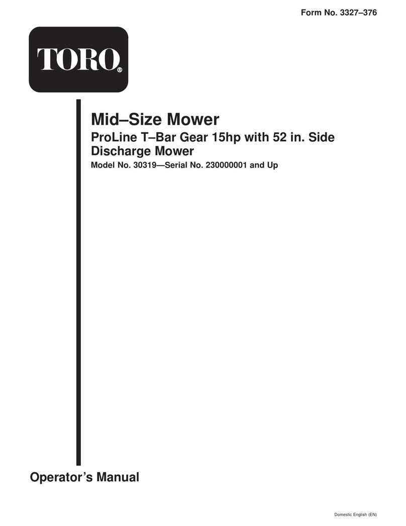
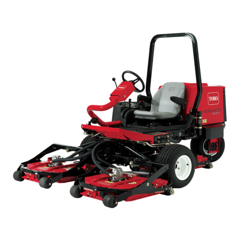
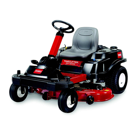
Toro 30645 User manual

FormNo.3395-143RevA
Base62inand72inMower
Groundsmaster®3400TractionUnit
ModelNo.30645—SerialNo.315000001andUp
ModelNo.30646—SerialNo.315000001andUp
Registeratwww.Toro.com.
OriginalInstructions(EN)*3395-143*A

WARNING
CALIFORNIA
Proposition65Warning
Thisproductcontainsachemicalorchemicals
knowntotheStateofCaliforniatocausecancer,
birthdefects,orreproductiveharm.
ThisproductcomplieswithallrelevantEuropeandirectives.
Fordetails,pleaseseetheDeclarationofIncorporation(DOI)
atthebackofthispublication.
Introduction
Thisrotary-blade,lawn-cuttingdecktoaride-onmachine
andisintendedtobeusedbyprofessional,hiredoperatorsin
commercialapplications.Itisprimarilydesignedforcutting
grassonwell-maintainedlawnsinparks,sportselds,andon
commercialgrounds.Itisnotdesignedforcuttingbrush,
mowinggrassandothergrowthalongsidehighways,orfor
agriculturaluses.
Readthisinformationcarefullytolearnhowtooperateand
maintainyourproductproperlyandtoavoidinjuryand
productdamage.Youareresponsibleforoperatingthe
productproperlyandsafely.
YoumaycontactTorodirectlyatwww.Toro.comforproduct
andaccessoryinformation,helpndingadealer,ortoregister
yourproduct.
Wheneveryouneedservice,genuineToroparts,oradditional
information,contactanAuthorizedServiceDealerorToro
CustomerServiceandhavethemodelandserialnumbers
ofyourproductready.Themodelandserialnumbersare
stampedintoaplatethatismountedonthemowerhousing.
Writethenumbersinthespaceprovided.
ModelNo.
SerialNo.
Thismanualidentiespotentialhazardsandhassafety
messagesidentiedbythesafetyalertsymbol(Figure1),
whichsignalsahazardthatmaycauseseriousinjuryordeath
ifyoudonotfollowtherecommendedprecautions.
Figure1
1.Safetyalertsymbol
Thismanualuses2wordstohighlightinformation.
Importantcallsattentiontospecialmechanicalinformation
andNoteemphasizesgeneralinformationworthyofspecial
attention.
©2015—TheToro®Company
8111LyndaleAvenueSouth
Bloomington,MN554202
Contactusatwww.Toro.com.
PrintedintheUSA.
AllRightsReserved

Contents
Safety...........................................................................3
SafeOperatingPractices...........................................3
ToroMowerSafety..................................................4
SafetyandInstructionalDecals.................................6
Setup............................................................................7
1InstallingaCompletionKit....................................7
2InstallingtheCastorWheelAssemblies....................7
3InstallingtheLiftArms..........................................8
4InstallingtheCuttingUnitontheLift
Arms.................................................................9
5ConnectingtheHydraulicDrive.............................10
6GreasingtheMachine...........................................11
ProductOverview.........................................................12
Specications........................................................12
Attachments/Accessories........................................12
Operation....................................................................12
AdjustingtheHeightofCut.....................................12
AdjustingtheCuttingUnitPitch...............................13
AdjustingtheSkids.................................................14
AdjustingtheRollers...............................................14
CorrectingCuttingUnitMismatch............................14
OperatingTips......................................................15
Maintenance.................................................................16
RecommendedMaintenanceSchedule(s)......................16
Lubrication............................................................16
...........................................................................17
SeparatingtheCuttingUnitfromtheTraction
Unit..................................................................17
MountingtheCuttingUnittotheTraction
Unit..................................................................18
ServicingtheBushingsintheCastorArms.................19
ServicingtheCastorWheelsandBearings..................19
CheckingforaBentBlade........................................20
RemovingandInstallingtheBlade............................20
InspectingandSharpeningtheBlade(s)......................21
CheckingandCorrectingMismatchof
Blades...............................................................21
ReplacingtheDriveBelt..........................................22
Safety
ThismachinehasbeendesignedinaccordancewithENISO
5395:2013andANSIB71.4-2012.
Improperuseormaintenancebytheoperatororownercan
resultininjury.Toreducethepotentialforinjury,comply
withthesesafetyinstructionsandalwayspayattentionto
thesafetyalertsymbol,whichmeansCaution,Warning,or
Danger—personalsafetyinstruction.Failuretocomplywith
theinstructionmayresultinpersonalinjuryordeath.
SafeOperatingPractices
Training
•Readtheoperator'smanualandothertrainingmaterial
carefully.Befamiliarwiththecontrols,safetysigns,and
theproperuseoftheequipment.Iftheoperatoror
mechaniccannotreadthelanguageofthismanual,itis
theowner'sresponsibilitytoexplainthismaterialtothem.
•Becomefamiliarwiththesafeoperationoftheequipment,
operatorcontrols,andsafetysigns.
•Alloperatorsandmechanicsshouldbetrained.The
ownerisresponsiblefortrainingtheusers
•Neverletchildrenoruntrainedpeopleoperateorservice
theequipment.Localregulationsmayrestricttheageof
theoperator.
•Theowner/usercanpreventandisresponsiblefor
accidentsorinjuriesoccurringtohimselforherself,other
people,orproperty.
Preparation
•Evaluatetheterraintodeterminewhataccessoriesand
attachmentsareneededtoproperlyandsafelyperform
thejob.Onlyuseaccessoriesandattachmentsapproved
bythemanufacturer.
•Wearappropriateclothingincludinghardhat,safety
glassesandearprotection.Longhair,looseclothingor
jewelrymaygettangledinmovingparts.
•Inspecttheareawheretheequipmentistobeusedand
removeallobjectssuchasrocks,toysandwirewhichcan
bethrownbythemachine.
•Useextracarewhenhandlinggasolineandotherfuels.
Theyareammableandvaporsareexplosive.
–Useonlyanapprovedcontainer.
–Neverremovefuelcaporaddfuelwithengine
running.Allowenginetocoolbeforerefueling.Do
notsmoke.
–Neverrefuelordrainthemachineindoors.
–Iffuelisspilled,donotattempttostarttheengine
butmovethemachineawayfromtheareaofspillage
andavoidcreatinganysourceofignitionuntilfuel
vaporshavedissipated.
–Replaceallfueltankandcontainercapssecurely.
3

•Replacefaultysilencers/mufers.
•Checkthatoperator'spresencecontrols,safetyswitches
andshieldsareattachedandfunctioningproperly.Donot
operateunlesstheyarefunctioningproperly.
•Beforeusing,alwaysvisuallyinspecttoseethatthe
blades,bladebolts,andcuttingassemblyarenotworn
ordamaged.
•Onmulti-bladedmachines,takecareasrotating1blade
cancauseotherbladestorotate.
Operation
•Neverrunanengineinanenclosedarea.
•Onlyoperateingoodlight,keepingawayfromholesand
hiddenhazards.
•Besurealldrivesareinneutralandparkingbrakeis
engagedbeforestartingengine.Onlystartenginefrom
theoperator'sposition.
•Slowdownanduseextracareonhillsides.Besureto
travelintherecommendeddirectiononhillsides.Turf
conditionscanaffectthestabilityofthemachine.Use
cautionwhileoperatingneardrop-offs.
•Slowdownandusecautionwhenmakingturnsandwhen
changingdirectionsonslopes.
•Whenusinganyattachments,neverdirectdischargeof
materialtowardbystandersnorallowanyonenearthe
machinewhileinoperation.
•Neverraisedeckwiththebladesrunning.
•Neveroperatewithguardsnotsecurelyinplace.Be
sureallinterlocksareattached,adjustedproperly,and
functioningproperty.
•Donotchangetheenginegovernorsettingoroverspeed
theengine.
•Stoponlevelground,lowerthecuttingunits,disengage
drives,engageparkingbrake(ifprovided),shutoffengine
andremovethekeyfromtheignitionbeforeleavingthe
operator'spositionforanyreason.
•Stoptheequipment,engageparkingbrake(ifprovided),
shutoffengine,removethekeyfromtheignitionand
inspectthebladesafterstrikingobjectsorifanabnormal
vibrationoccurs.Makenecessaryrepairsbeforeresuming
operations.
•Keephandsandfeetawayfromthecuttingunits.
•Lookbehindanddownbeforebackinguptobesureof
aclearpath.
•Whenmachineistobeparked,stored,orleftunattended,
lowerthecuttingunitsunlessapositivemechanicallock
isprovided.
•Nevercarrypassengersandkeeppetsandbystanders
away.
•Slowdownandusecautionwhenmakingturnsand
crossingroadsandsidewalks.Stopbladesifnotmowing.
•Donotoperatethemowerundertheinuenceofalcohol
ordrugs.
•Lightningcancausesevereinjuryordeath.Iflightning
isseenorthunderisheardinthearea,donotoperate
themachine;seekshelter.
•Usecarewhenloadingorunloadingthemachineintoa
trailerortruck.
•Usecarewhenapproachingblindcorners,shrubs,trees,
orotherobjectsthatmayobscurevision.
•Theoperatorshallturnonashingwarninglights,if
provided,whenevertravelingonapublicroad,except
wheresuchuseisprohibitedbylaw .
MaintenanceandStorage
•Disengagedrives,lowerthecuttingunits,movetraction
pedaltoNeutral,setparkingbrake,stopengineand
removekey.Waitforallmovementtostopbefore
adjusting,cleaningorrepairing.
•Cleangrassanddebrisfromcuttingunits,drives,mufer
andenginetohelppreventres.Letenginecoolbefore
storinganddonotstorenearames.Cleanupoilor
fuelspillage.
•Letenginecoolbeforestoringanddonotstorenear
ame.
•Donotstorefuelnearamesordrainindoors.
•Parkmachineonlevelground.Neverallowuntrained
personneltoservicemachine.
•Usejackstandstosupportcomponentswhenrequired.
•Carefullyreleasepressurefromcomponentswithstored
energy.
•Disconnectbatterybeforemakinganyrepairs.Disconnect
thenegativeterminalrstandthepositivelast.Connect
positiverstandnegativelast.
•Usecarewhencheckingblades.Wrapthebladesor
weargloves,andusecautionwhenservicingthem.Only
replaceblades.Neverstraightenorweldthem.
•Keephandsandfeetawayfrommovingparts.Ifpossible,
donotmakeadjustmentswiththeenginerunning.
•Chargebatteriesinanopenwellventilatedarea,away
fromsparkandames.Unplugchargerbeforeconnecting
ordisconnectingfrombattery.Wearprotectiveclothing
anduseinsulatedtools.
•Keepallpartsingoodworkingconditionandallhardware
tightened.Replaceallwornordamageddecals.
ToroMowerSafety
ThefollowinglistcontainssafetyinformationspecictoToro
productsorothersafetyinformationthatyoumustknowthat
isnotincludedintheCENstandard.
Thisproductiscapableofamputatinghandsandfeetand
throwingobjects.Alwaysfollowallsafetyinstructionsto
avoidseriousinjuryordeath.
Useofthisproductforpurposesotherthanitsintendeduse
couldprovedangeroustouserandbystanders.
4
•Knowhowtostoptheenginequickly.
•Donotoperatethemachinewhilewearingtennisshoes
orsneakers.
•Wearingsafetyshoesandlongpantsisadvisableand
requiredbysomelocalordinancesandinsurance
regulations.
•Handlefuelcarefully.Wipeupanyspills.
•Checkthesafetyinterlockswitchesdailyforproper
operation.Ifaswitchshouldfail,replacetheswitch
beforeoperatingthemachine.
•Usingthemachinedemandsattention.Topreventloss
ofcontrol:
–Donotdriveclosetosandtraps,ditches,creeks,
embankments,orotherhazards.
–Avoidsuddenstopsandstarts.
–Whennearorcrossingroads,alwaysyieldthe
right-of-way.
–Lowerthecuttingunitwhengoingdownslopes.
•Thegrassdeectormustalwaysbeinstalledandinthe
lowestpositiononthesidedischargecuttingunit.Never
operatethemowerwithoutthedeectororentiregrass
collector.
•Ifthecuttingunitdischargeareaeverplugs,shutthe
engineoff,engagetheparkingbrakeandremovethekey
fromtheignitionbeforeremovingtheobstruction.
•Cutgrassslopescarefully.Donotstart,stop,orturn
suddenly.
•Donottouchtheengineormuferwhiletheengineis
runningorsoonafterithasstoppedbecausetheseareas
couldbehotenoughtocauseburns.
MaintenanceandStorage
•Checktheblademountingboltsfrequentlytobesurethat
theyaretightenedtospecication.
•Makesurethatallhydrauliclineconnectorsaretightand
allhydraulichosesandlinesareingoodconditionbefore
applyingpressuretothesystem.
•Keepyourbodyandhandsawayfrompinholeleaksor
nozzlesthatejecthydraulicuidunderhighpressure.
Usepaperorcardboard,notyourhands,tosearchfor
leaks.Hydraulicuidescapingunderpressurecanhave
sufcientforcetopenetratetheskinandcauseserious
injury.
•Beforedisconnectingorperforminganyworkonthe
hydraulicsystem,allpressureinthesystemmustbe
relievedbystoppingtheengineandloweringthecutting
unitstotheground.
•Iftheenginemustberunningtoperformamaintenance
adjustment,keephands,feet,clothing,andanypartsof
thebodyawayfromthecuttingunits,attachments,and
anymovingparts.Keepeveryoneaway.
•Donotoverspeedtheenginebychanginggovernor
settings.Toensuresafetyandaccuracy,havean
AuthorizedToroDistributorcheckthemaximumengine
speedwithatachometer.
•Theenginemustbeshutoffbeforecheckingtheoilor
addingoiltothecrankcase.
•Performonlythosemaintenanceinstructionsdescribed
inthismanual.Ifmajorrepairsareeverneededor
ifassistanceisdesired,contactanAuthorizedToro
Distributor.
•Toensureoptimumperformanceandcontinuedsafety
certicationofthemachine,useonlygenuineToro
replacementpartsandaccessories.Replacementparts
andaccessoriesmadebyothermanufacturerscouldbe
dangerous,andsuchusecouldvoidtheproductwarranty.
5

SafetyandInstructionalDecals
Safetydecalsandinstructionsareeasilyvisibletotheoperatorandarelocatednearanyareaofpotential
danger.Replaceanydecalthatisdamagedorlost.
120-6604
1.Thrownobjecthazard—keepbystandersawayfromthe
machine.
2.Cutting/dismembermenthazardofhand,mower
blade—stayawayfrommovingparts,keepallguardsand
shieldsinplace.
3.Cutting/dismembermenthazardoffoot,mowerblade—stay
awayfrommovingparts,keepallguardsandshieldsin
place.
93-7818
1.Warning—readtheOperator'sManualforinstructionson
torquingthebladebolt/nutto115-149N-m(85-110ft-lb).
117–4979
1.Entanglementhazard,belt—stayawayfrommovingparts,
keepallguardsandshieldsinplace.
108-1988
1.Beltrouting
100-5622
1.Height-of-cutadjustment
108-1986
1.Height-of-cut
6

Setup
LooseParts
Usethechartbelowtoverifythatallpartshavebeenshipped.
ProcedureDescriptionQty.Use
1Completionkit(soldseparately)1Installacompletionkit.
2Castorwheelassembly2Installthecastorwheelassemblies.
Lift-arm,right1
Lift-arm,left1
Liftcylinderpin2
Cylindercarriagebolt2
3
Cylinderangenut2
Installtheliftarms.
Thrustwasher4
Clevispin4
Hairpincotter2
Height-of-cutcollar2
Clevispin2
4
Hairpincotter2
Installthecuttingunits.
5Nopartsrequired–Connectthehydraulicdrive.
6Nopartsrequired–Greasethemachine.
MediaandAdditionalParts
DescriptionQty.Use
PartsCatalog1
Operator'sManual1
Readthecontentsofthesematerialsandstorethemin
asafelocation.
DANGER
Iftheengineisstartedandyouhavenotcorrectly
connectedthehydraulichoses,seriousinjurycan
result.
Youmustmakesurethatthehydraulichosesare
correctlyconnectedorthatblankingplugshave
beenttedbeforestartingtheengineandengaging
thecuttingunit.
Note:Determinetheleftandrightsidesofthemachine
fromthenormaloperatingposition.
1
InstallingaCompletionKit
Partsneededforthisprocedure:
1Completionkit(soldseparately)
Procedure
Installoneofthefollowing62inchor72inchcompletionkits
tothebasedeckusingtheinstructionprovidedinthekit:
•Model30648,62inchRearDischarge
•Model30306,62inchGuardian
•Model30649,72inchRearDischarge
•Model30304,72inchGuardian
7

2
InstallingtheCastorWheel
Assemblies
Partsneededforthisprocedure:
2Castorwheelassembly
Procedure
Thethrustwashers,spacers,andtensioningcapshavebeen
installedonthecastorwheelspindlesforshipping.
1.Removethetensioningcapsfromthespindleshafts
andslideoffthespacersandthrustwashers(Figure2).
Figure2
1.Tensioningcap4.Axlemountingholes
2.Spacers5.Castorwheel
3.Thrustwashers
2.Slidethespacersontothecastorspindletogetthe
desiredheightofcut;refertoFigure7andFigure8to
determinethecombinationsofspacersforthesetting.
3.Slideathrustwasherontothespindle,pushthecastor
throughthecastor-arm.
4.Installanotherthrustwasherandtheremainingspacers
ontothespindleandinstallthetensioningcaptosecure
theassembly(Figure2).
3
InstallingtheLiftArms
Partsneededforthisprocedure:
1Lift-arm,right
1Lift-arm,left
2Liftcylinderpin
2Cylindercarriagebolt
2Cylinderangenut
Procedure
1.Placethefrontendofthetractionunitupon2axle
standsusingtheappropriateequipment.Ensurethe
machineissafetoworkaround.
2.Removethefrontwheels.
3.Releasethecabletiesthatareholdingupthetraction
unitliftcylindersandlowerthemtotheoor.
4.Openandraisetheoperator'splatformonthetraction
unit.
5.Fromthefrontofthetractionunitandunderthe
raisedoperatorplatform,removethenutsandcarriage
boltsthatsecurethelift-arm,pivotpinstothetraction
unitandremovetheleftandright,lift-arm,pivotpins
(Figure3).
8

g029329
1
2
3
4
5
1
23
6
7
8
910
11
Figure3
1.Cylinder-carriagebolt7.M24washer
2.Lift-cylinderpin8.M24bolt
3.Cylinder-angenut9.Wearplate
4.Leftliftarm10.Nut
5.Rightliftarm11.Armpin
6.Carriagebolt
6.Mounttheliftarmstothetractionunitwiththe
bendspositionedoutward,andsecurethemusingthe
previouslyremovedlift-armpivotpins,carriagebolts,
andnuts(Figure3).
7.Raiseandsecuretheliftarms.
8.Turnonthetraction-unitignitionandmovethecutting
unittotheFLOATposition.
9.Securethelift-cylinderstotheliftarmsusingthe
suppliedliftcylinderpins,carriagebolts,andnuts.
10.Turnoffthetractionunit,andlowerandsecurethe
operatorplatform.
11.Installthe2frontwheelsandplacethemachineback
ontotheoor.
4
InstallingtheCuttingUniton
theLiftArms
Partsneededforthisprocedure:
4Thrustwasher
4Clevispin
2Hairpincotter
2Height-of-cutcollar
2Clevispin
2Hairpincotter
Procedure
1.Movethecuttingunitintopositioninfrontofthe
tractionunit.
2.Turnonthetractionunitignitionandmovethecutting
unittotheFLOATposition.
3.Pushalift-armdownuntiltheholesinthelift-armline
upwiththeholesinthecastor-armbracketandthe
height-of-cutrodisabletobeinsertedintothelift-arm
pads(Figure4).
4.Securethelift-armtothecastor-armwith2thrust
washers,aclevispinandahair-pincotter.
Note:Positionthethrustwashersbetweenthelift-arm
andthecastor-armbracket(Figure4).Insertendof
cotterpinintotheslotinthecastor-armtabtoretain
cotterpin.
5.Repeatstep3and4ontheoppositelift-arm.
6.Startthetractionunitandraisethecutting-unit.
7.Pushdownontherearofthecuttingunitandinsert
theheight-of-cutrodsthroughthelift-armpads.
8.Installtheheight-of-cutcollarsontotheheight-of-cut
rodsandsecurethemwiththeclevispinsandhairpin
cotters(Figure4).
9.Lowerthedeckandswitchthetraction-unitignition
switchtotheOFFposition.
9

g017950
1
2
3
4
5
6
7
8
9
10
Figure4
1.Lift-arm6.Clevispin
2.Castor-armbracket7.Hairpincotter
3.Height-of-cutrod8.Height-of-cutcollar
4.Lift-armpads9.Clevispin
5.Thrustwashers10.Hairpincotter
5
ConnectingtheHydraulic
Drive
NoPartsRequired
Procedure
Important:Foryoursafetythecutter-valve,electrical
connectorhasbeendisconnectedtodisablethe
operationofthecutterdrive.Connecttheelectrical
connectorafterallhoselineconnectionshavebeen
madecorrectly.
WARNING
Hydraulicuidescapingunderpressurecan
penetrateskinandcauseinjury.
•Makesurethatallhydraulicuidhosesand
linesareingoodconditionandallhydraulic
connectionsandttingsaretightbefore
applyingpressuretothehydraulicsystem.
•Keepyourbodyandhandsawayfrompin
holeleaksornozzlesthatejecthighpressure
hydraulicuid.
•Usecardboardorpapertondhydraulicleaks.
•Safelyrelieveallpressureinthehydraulicsystem
beforeperforminganyworkit.
•Seekimmediatemedicalattentionifuidis
injectedintoyourskin.
Note:Somehydraulicuidlossmayoccur.
1.Turnoffthecuttingunits,lowerthem,stoptheengine,
engagetheparkingbrake,andremovetheignitionkey.
2.Cleantheareasaroundthehydraulicportsandthe
hydraulic-hoseends(Figure5).
g017951
12
3
4
56
Figure5
1.Blankingcap(5/8inch)4.Drainport(tocutting-unit
valveteeonCDport)
2.Blankingcap(3/8inch)5.Returnport(tocutting-unit
valveM2port)
3.Cableties6.Pressureport(from
cutting-unitvalveM1port)
3.Identifythe3hydraulichoselinesandports.Refer
toFigure5fortheappropriateportforeachhose.
Performthefollowingprocessforeachconnection:
A.Removethehose-lineplug.
B.Removetheportcap.
C.Connectthehosetotheport.
10

D.Tighteneachhoseconnection.
4.Routeallhosescorrectly,cleantheconnections,and
tightenallhoselines.Retainthehoseplugsandport
capsforfutureuse.
5.Usethecabletiesprovidedtosecurethehoselines.
6.Raisetheoperator'splatformonthetractionunit,and
connectthecutter-valve,electricalconnector(Figure6).
g017952
1
Figure6
1.Cutter-valveelectricalport
7.Checktheuidlevels,securetheoperator'splatform
onthetractionunit,andverifythatthecuttingunitis
workingcorrectly.
6
GreasingtheMachine
NoPartsRequired
Procedure
Toensureproperlubrication,youmustgreasethemachine
beforeoperation;refertoLubrication(page16).Ifyoufail
toproperlylubricatethemachine,prematurefailureofparts
willresult.
11

ProductOverview
Specications
Note:Specicationsanddesignaresubjecttochange
withoutnotice.
WidthofCut1.575m(62inches)or1.829m(72inches)
HeightofCutAdjustablefrom25to127mm(1to5inches)
in13mm(1/2inch)increments
NetWeightModel30645–210kg(463lbs.)
Model30646–225kg(496lbs.)
Attachments/Accessories
AselectionofToroapprovedattachmentsandaccessoriesis
availableforusewiththemachinetoenhanceandexpand
itscapabilities.ContactyourAuthorizedServiceDealeror
Distributor.
Tobestprotectyourinvestmentandmaintainoptimal
performanceofyourToroequipment,countonTorogenuine
parts.Whenitcomestoreliability,Torodeliversreplacement
partsdesignedtotheexactengineeringspecicationofour
equipment.Forpeaceofmind,insistonTorogenuineparts.
Operation
Note:Determinetheleftandrightsidesofthemachine
fromthenormaloperatingposition.
AdjustingtheHeightofCut
Adjusttheheightofcutfrom25to127mm(1to5inches)
in13mm(1/2inch)increments.Toadjusttheheightofcut,
positionthecastorwheelaxlesintheupperorlowerholesof
thecastorforks,addorremoveanequalnumberofspacers
fromthecastorforks,andsecuretheheight-of-cutcollarto
thedesiredholesintheheight-of-cutrod.
1.Starttheengineandraisethecuttingunitofftheoor.
Stoptheengineandremovethekey.
2.Positionthecastorwheelaxlesinthesameholesin
bothcastorforks.RefertoFigure7andFigure8to
determinethecorrectholesforthesetting.
Note:Whenoperatingin64mm(2–1/2inch)height
ofcutorhigher,installtheaxleboltinthelower
castorforkholetopreventgrassbuildupbetweenthe
wheelandthefork.Whenoperatinginheightofcuts
lowerthan64mm(2–1/2inches)andgrassbuildup
isdetected,reversethemachinedirectiontopullany
clippingsawayfromthewheel/forkarea.
3.Removethetensioningcapfromthespindleshaft
(Figure7)andslidethespindleoutofthecastorarm.
4.Putthe2shims(1/8inch)ontothespindleshaftas
theywereoriginallyinstalled.
Note:Theseshimsarerequiredtoachievealevel
acrosstheentirewidthofthecuttingunits.
5.Slidetheappropriatenumberof1/2inchspacersonto
thespindleshafttogetthedesiredheightofcut;then
slidethewasherontotheshaft.
RefertoFigure7andFigure8todeterminethe
combinationsofspacersforthesetting.
12

Figure7
1.Tensioningcap4.Axle-mountingholes
2.Spacers5.Castorwheel
3.Shims
Figure8
6.Pushthecastorspindlethroughthecastorarm.
7.Installtheshims(astheywereoriginallyinstalled)and
theremainingspacersontothespindleshaft.
8.Installthetensioningcaptosecuretheassembly.
9.Removethehair-pinandclevispinsecuringthe
height-of-cutcollartotheheight-of-cutrodontherear
ofthecuttingunit(Figure9).
Figure9
1.Height-of-cutrod3.Clevispinandhairpin
cotter
2.Height-of-cutcollar
10.Aligntheheight-of-cutcollartothedesired
height-of-cutholesontheheight-of-cutrod(Figure
10).
Figure10
11.Securetheadjustmentwiththeclevispinandhair-pin
cotter.
Note:Positiontheheadoftheclevispintowardthe
frontofthedeck,ifpossible.
Note:Whenusing25mm(1inch),38mm(1-1/2
inch),oroccasionally51mm(2inch)heightofcut,
movetheskidsandrollertothehighestholes.
AdjustingtheCuttingUnit
Pitch
Cuttingunitpitchisthedifferenceinheightofcutfromthe
frontofthebladeplanetothebackofthebladeplane.Toro
recommendsabladepitchof13mm(1/2inch).Thatisthe
13

backofthebladeplaneis13mm(1/2inch)higherthanthe
front.
1.Positionthemachineonalevelsurfaceontheshop
oor.
2.Setthecuttingunittothedesiredheightofcut.
3.Rotate1bladesothatitpointsstraightforward.
4.Usingashortruler,measurefromtheoortothefront
tipoftheblade.Rotatethebladetiptotherearand
measurefromtheoortothetipoftheblade.
5.Subtractthefrontdimensionfromthereardimension
tocalculatethebladepitch.
6.Loosenthejamnutsonthebottomoftheheight-of-cut
rods(Figure11).
Figure11
1.Height-of-cutrod2.Jamnut
7.Rotatetheheight-of-cutrodstoraiseorlowertherear
ofthecuttingunitandattainthecorrectcuttingunit
pitch.
8.Tightenthejamnuts.
AdjustingtheSkids
Mounttheskidsinthelowerpositionwhenoperatingin
heightofcutsgreaterthan64mm(2-1/2inches)andinthe
higherpositionwhenoperatinginheightofcutslowerthan
64mm(2-1/2inches).
Adjusttheskidsbyremovingtheangeboltandnuts,
positioningthemasdesired,andinstallingthefasteners
(Figure12).
Figure12
1.Skid
AdjustingtheRollers
Note:Whenthecuttingunitisbeingusedinthe25or38
mm(1or1-1/2inch)height-of-cutsetting,thecuttingunit
rollersmustberepositionedinthetopbracketholes.
1.Removethescrewandnutsecuringtherollershaftto
thedeckbracket(Figure13).
Figure13
1.Roller2.Rollershaft
2.Slidetheshaftoutofthelowerbracketholes,alignthe
rollerwiththetopholes,andinstalltheshaft.
3.Installthescrewandnuttosecuretheassemblies.
CorrectingCuttingUnit
Mismatch
Duetodifferencesingrassconditionsandthecounterbalance
settingofthetractionunit,cutgrassandcheckappearances
beforestartingformalcutting.
1.Setthecuttingunittothedesiredheightofcut;referto
AdjustingtheHeightofCut(page12).
2.Checkandadjustfrontandreartractortirepressureto
0.7bar(10psi).
3.Checkandadjustallcastortirepressuresto3.4bar
(50psi).
14

4.Checkforbentblades;refertoCheckingforaBent
Blade(page20).
5.Cutgrassinatestareatodetermineifallcuttingunits
arecuttingatthesameheight.
6.Whencuttingunitadjustmentsarestillneeded,nda
atsurfaceusinga2m(6foot)orlongerstraightedge.
7.Toeasemeasuringbladeplane,raisetheheightofcut
tothehighestposition;refertoAdjustingtheHeight
ofCut(page12).
8.Lowercuttingunitontotheatsurface.Removethe
coversfromthetopofthecuttingunits.
9.Rotatethebladeoneachspindleuntiltheendsface
forwardandbackward.
10.Measurefromtheoortothefronttipofthecutting
edge.
11.Adjustthe3mm(1/8inch)shimsonthecastorfork(s)
tomatchtheheightofcuttodecal(Figure14);referto
AdjustingtheCuttingUnitPitch(page13).
Figure14
1.Tensioningcap4.Axle-mountingholes
2.Spacers5.Castorwheel
3.Shims
OperatingTips
MowWhenGrassIsDry
Moweitherinthelatemorningtoavoidthedew,whichcauses
grassclumping,orinlateafternoontoavoidthedamage
thatcanbecausedbydirectsunlightonthesensitive,freshly
mowedgrass.
SelecttheProperHeight-of-CutSetting
toSuitConditions
Removeapproximately25mm(1inch)ornomorethan1/3
ofthegrassbladewhencutting.Inexceptionallylushand
densegrass,youmayhavetoraisetheheight-of-cuttothe
nextsetting.
MowatProperIntervals
Undermostnormalconditionsyouwillneedtomow
approximatelyevery4or5days.Butremember,grassgrows
atdifferentratesatdifferenttimes.Thismeansthatinorder
tomaintainthesameheightofcut,whichisagoodpractice,
youwillneedtocutmorefrequentlyinearlyspring;asthe
grassgrowthrateslowsinmidsummer,cutonlyevery8or
10days.Ifyouareunabletomowforanextendedperioddue
toweatherconditionsorotherreasons,mowrstwiththe
heightofcutatahighlevel;thenmowagain2or3dayslater
withalowerheightsetting.
AlwaysMowwithSharpBlades
Asharpbladecutscleanlyandwithouttearingorshredding
thegrassbladeslikeadullblade.Tearingandshredding
causesthegrasstoturnbrownattheedgeswhichimpairs
growthandincreasessusceptibilitytodiseases.
AfterOperating
Toensureoptimumperformance,cleantheundersideofthe
mowerhousingaftereachuse.Ifresidueisallowedtobuild
upinthemowerhousing,cuttingperformancewilldecrease.
CuttingUnitPitch
Werecommendabladepitchof13mm(1/2inch).A
pitchlargerthan13mm(1/2inch)willresultinlesspower
required,largerclippings,andapoorerqualityofcut.Apitch
lessthan13mm(1/2inch)willresultinmorepowerrequired,
smallerclippingsandabetterqualityofcut.
15

Maintenance
Important:Thefastenersonthecoversofthismachine
aredesignedtoremainonthecoverafterremoval.
RecommendedMaintenanceSchedule(s)
MaintenanceService
IntervalMaintenanceProcedure
Aftertherst10hours•Torquethebladebolts.
Beforeeachuseordaily•Checktheblades.
Every50hours
•Lubricatethegreasettings.
•Checkthegearbox-oillevel.
•Torquethebladebolts.
•Checktheblade-drive-beltadjustment.
•Cleanunderthecutting-unitbelt-covers.
Every400hours•Changethegearboxoil.
CAUTION
Ifyouleavethekeyintheignitionswitch,someonecouldaccidentallystarttheengineandseriously
injureyouorotherbystanders.
Removethekeyfromtheignitionswitchbeforeyoudoanymaintenance.
Lubrication
ServiceInterval:Every50hours
Every50hours
Every400hours
Note:Immediatelyaftereverywashing,regardlessofthe
intervallisted
Lubricatethettingonthismachineregularlywithno.2
general-purpose,lithium-basedgrease.Ifthemachineis
operatedundernormalconditions,lubricateallbearingsand
bushingsafterevery50hoursofoperationorimmediately
aftereverywashing.
Lubricatethefollowingareas:
•2caster-fork-shaftbushings(Figure15)
Figure15
•3spindle-shaftbearings(locatedunderthepulley)(Figure
16).
g017953
Figure16
•Idler-arm-shaftbearings(Figure16).
16

•2lift-armpivots,front(Figure17).
g017954
Figure17
•2lift-armpivots,rear(Figure18).
g017955
Figure18
TiltingtheCuttingUnit
1.Positionthemachineonalevelsurface,raisethe
cuttingunit,turnofftheengine,engagetheparking
break,andapplythelift-armlatches.
Note:Ifthecuttingunitisa183cm(72inch)model
withareardischargekittted,therearleftfootguard
shouldberemovedpriortocarryingoutthisoperation.
2.Removethehairpincotterandclevispinsecuring
theheight-of-cutcollartotheheight-of-cutrodon
therearofthecuttingunit(Figure19).Removethe
height-of-cutcollars.
g017956
1
23
4
5
6
8
7
9
10
Figure19
1.Lift-armlatches6.Lift-armpads
2.Hairpincotter7.Clevispin
3.Clevispin8.Hairpincotter
4.Height-of-cutcollar9.Rightliftarm
5.Height-of-cutrod10.Rightcasterarm
3.Pivotthedeckuntiltheclevispinwilltthroughthe
holeintherightcastorarmandsecureittotheright
liftarm.Securetheclevispinwithaharipincotter
(Figure19).
LoweringtheCuttingUnitfromthe
TiltedPosition
1.Removethehairpincotter.
2.Liftthedeckuntiltheclevispincanbeeasilyremoved
fromtheholeintherightcastor-arm(Figure19).
3.Lowerandtiltthedeckbackensuringtheheight-of-cut
rodsdonotgetcaughtonanypartofthetractionunit.
4.Pushdownontherear,rightsideofthecuttingunitand
inserttheheight-of-cutrodsthroughthelift-armpads.
5.Repeatfortheleftside,makingsurethattherightside,
height-of-cutroddoesnotfallout(Figure19).
6.Installtheheight-of-cutcollarsontotheheight-of-cut
rodsandsecurethemwiththeclevispinsandhairpin
cotters(Figure19).
Note:Makesurethattheheadoftheclevispinis
towardthefrontofthedeck.
SeparatingtheCuttingUnit
fromtheTractionUnit
1.Positionthemachineonlevelsurface,raisethecutting
unit,movetheliftlevertotheFLOATposition,shutthe
engineoff,andengagetheparkingbrake.
17

2.Removethehairpincotterandclevispinsecuringthe
height-of-cutrodtotherearofthecuttingunit(Figure
20).Removetheheight-of-cutcollars.
g017957
1
2
3
Figure20
1.Height-of-cutrod3.Hairpincotterandclevis
pin
2.Height-of-cutcollar
3.Turnontheignitionswitchandlowerthecuttingunit
totheoor.
Note:LeavetheliftswitchintheFLOATposition.
Note:Makesuretheengineisnotrunning.
4.Removethehairpincottersandclevispinssecuringthe
liftarmstothecastor-armbrackets(Figure21).
g017958
1
23
4
Figure21
1.Lift-arm3.Hairpincotter
2.Clevispin4.Castor-armbracket
5.Removethehydraulicmotorcovers,removethebolts,
thenremovethehydraulicmotorfromthecuttingunit.
(Figure22).
g017959
1
2
3
Figure22
6.Raisetheliftarms,latchthemintheraisedposition,
androllthecuttingunitawayfromthetractionunit.
Turnofftheignitionswitch.
CAUTION
Donotengagethecuttingunitdrivewhile
thehydraulicmotorisnotconnectedtothe
cuttingunit.
MountingtheCuttingUnitto
theTractionUnit
1.Positionthemachineonalevelsurfaceandshutthe
engineoff.Leavetheignitionswitchon.
2.Movethecuttingunitintopositioninfrontofthe
tractionunit.
3.Installthehydraulicmotorontothecuttingunit,secure
itusingthe2bolts,theninstallthe2hydraulicmotor
covers(Figure22).
4.MovetheliftswitchtotheFLOATposition.
5.Pushaliftarmdownuntiltheholesintheliftarmline
upwiththeholesinthecastor-armbracketandthe
height-of-cutrodcanbeinsertedintothelift-armpads
(Figure23).
18

g017960
1
2
3
4
5
6
7
8
9
10
Figure23
1.Liftarm6.Pin
2.Castor-armbracket7.Hairpincotter
3.Height-of-cutrod8.Height-of-cutcollar
4.Lift-armpads9.Clevispin
5.Thrustwashers10.Hairpincotter
6.Securetheliftarmtothecastorarmwith2thrust
washers,aclevispin,andahair-pincotter.
7.Positionthethrustwashersbetweentheliftarmand
thecastor-armbracket(Figure23).
8.Inserttheendofthehairpincotterintotheslotinthe
castor-armbrackettoretainthepin.
9.Repeattheprocedureontheotherliftarm.
10.Startthetractionunitandraisethecuttingunit.
11.Workingontherightside,pushdownontherear
ofthecuttingunitandinserttheheight-of-cutrods
throughthelift-armpads.
12.Repeatstep11ontheleftside,takingcarenottoallow
therightsideheight-of-cutrodtofallout.
13.Installtheheight-of-cutcollarsontotheheight-of-cut
rodsandsecurewiththeclevispinsandhair-pincotters
(Figure23).
Note:Theheadoftheclevispinmustbepositioned
towardthefrontofthedeck.
ServicingtheBushingsinthe
CastorArms
Thecastorarmshavebushingspressedintothetopand
bottomofthetubeandaftermanyhoursofoperation,the
bushingswillwear.Tocheckthebushings,movethecastor
forkbackandforthandfromsidetoside.Ifthecastor
spindleislooseinsidethebushings,thebushingsareworn;
replacethemasfollows:
1.Raisethecuttingunitsothatthewheelsareoffof
theoor.Latchthecuttingunitsothatitcannot
accidentallyfall.
2.Removethetensioningcap,spacer(s),andthrust
washerfromthetopofthecastorspindle.
3.Pullthecastorspindleoutofthemountingtube.
Allowthethrustwasherandspacer(s)toremainon
thebottomofthespindle.
4.Insertapinpunchintothetoporbottomofthe
mountingtubeanddrivethebushingoutofthetube
(Figure24).
5.Drivetheotherbushingoutofthetube.Cleanthe
insideofthetubestoremovedirt.
Figure24
1.Castor-armtube2.Bushings
6.Applygreasetotheinsideandoutsideofthenew
bushings.Usingahammerandatplate,drivethe
bushingsintothemountingtube.
7.Inspectthecastorspindleforwearandreplaceitif
damaged.
8.Pushthecastorspindlethroughthebushingsand
mountingtube.Slidethethrustwasherandspacer(s)
ontothespindle.Installthetensioningcaponthe
castorspindletoretainallpartsinplace.
ServicingtheCastorWheels
andBearings
1.Removethelocknutfromtheboltholdingthecastor
wheelassemblybetweenthecastorfork(Figure25).
Graspthecastorwheelandslidetheboltoutofthe
forkorpivotarm.
19

Figure25
1.Castorwheel3.Bearing(2)
2.Castorfork4.Bearingspacer
2.Removethebearingfromthewheelhubandallow
thebearingspacertofallout(Figure25).Removethe
bearingfromtheoppositesideofthewheelhub.
3.Checkthebearings,spacer,andinsideofthewheelhub
forwear.Replaceanydamagedparts.
4.Toassemblethecastorwheel,pushthebearingintothe
wheelhub.Wheninstallingthebearings,pressonthe
outerraceofthebearing.
5.Slidethebearingspacerintothewheelhub.Pushthe
otherbearingintotheopenendofthewheelhubto
captivatethebearingspacerinsidethewheelhub.
6.Installthecastorwheelassemblybetweenthecastor
forkandsecureitinplacewiththeboltandlocknut.
CheckingforaBentBlade
1.Positionthemachineonalevelsurface.Raisethe
cuttingunit,engagetheparkingbrake,putthetraction
pedalinneutral,putthecuttingunitdriveswitchinthe
OFFposition,stoptheengine,andremovetheignition
key.
Note:Latchthecuttingunittopreventitfrom
accidentallyfalling.
2.Rotatethebladeuntiltheendsfaceforwardand
backward.
Note:Measurefromtheinsideofthecuttingunitto
thecuttingedgeatthefrontoftheblade(Figure26),
andrememberthisdimension.
G010549
Figure26
3.Rotatetheoppositeendofthebladeforward.Measure
betweenthecuttingunitandcuttingedgeoftheblade
atthesamepositionasinstep2.
Note:Thedifferencebetweenthedimensions
obtainedinsteps2and3mustnotexceed3mm(1/8
inch).Ifthedimensionexceeds3mm(1/8inch),
replacethebladebecauseitisbent;refertoRemoving
andInstallingtheBlade(page20).
RemovingandInstallingthe
Blade
ServiceInterval:Aftertherst10hours
Every50hours
Replacethebladeifithitsasolidobject,isoutofbalance,
worn,orbent.AlwaysusegenuineTororeplacementblades
toensuresafetyandoptimumperformance.Neveruse
bladesmadebyothermanufacturersbecausetheycouldbe
dangerous.
1.Raisethecuttingunittothehighestposition,engage
theparkingbrake,stoptheengine,andremovethe
ignitionkey.
Note:Latchthecuttingunittopreventitfrom
accidentallyfalling.
2.Grasptheendofthebladeusingaragorthickly
paddedglove.Removethebladebolt,anti-scalpcup,
andbladefromthespindleshaft(Figure27).
G010555
1
2
Figure27
1.Bladebolt2.Anti-scalpcup
3.Installthebladeandanti-scalpcupusingthebladebolt
(Figure27).
Important:Thecurvedpartoftheblademustbe
pointingtowardtheinsideofthecuttingunitto
ensurepropercutting.
4.Tightenthebladeboltto115-149N-m(85-110ft-lb).
20
Other manuals for 30645
1
This manual suits for next models
2
Table of contents
Other Toro Lawn Mower manuals

Toro
Toro Super Recycler 21680 User manual

Toro
Toro 22168TE User manual

Toro
Toro Reelmaster 5610-D User manual

Toro
Toro 20812 User manual

Toro
Toro 30162 User manual

Toro
Toro 4036 User manual

Toro
Toro GrandStand 74534 User manual

Toro
Toro TITAN User manual

Toro
Toro Recycler 20074A User manual

Toro
Toro ProLine 30196 User manual