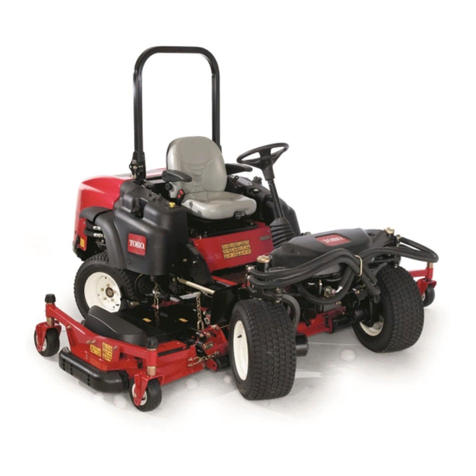
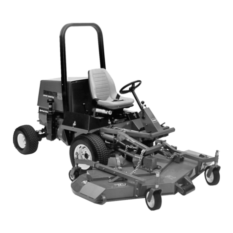
Toro Z Master Series Manual

FormNo.3375-555RevC
ZMaster®RidingMower
ForAllZMaster®RidingMowersSetupInstructions
Setup
LooseParts
Usethechartbelowtoverifythatallpartshavebeenshipped.
ProcedureDescriptionQty.Use
1Rearwheels(Woodencrateonly)2Removethemachinefromacrate.
2Nopartsrequired–Addfueltothemachine.
3Nopartsrequired–Checktheengine-oillevel.
4Nopartsrequired–Checkthetirepressure.
5Nopartsrequired–Checkthewheellugnuttorque.
6Nopartsrequired–Checkthegrassdeector.
J-bolt2
Wingnut2
7Hold-downclamp1
Installabattery(Dieselmachinesonly).
Clamp1
Wingnut(1/4inch)2
8Batteryhold-down2
Installabattery(Gasolinemachines
only).
9Nopartsrequired–Chargethebattery.
Seat1
Seatplate(xedseatsonly)1
Flangenuts(3/8inch)—xedseatsonly8
Spacers(3/8inch)—xedseatsonly4
Flangenuts(3/8inch)—tiltingseatsonly4
Longspacers(tilting,deluxeseatsonly)2
10
Shortspacers(tilting,deluxeseatsonly)4
Installtheseat(Internationalmachines
usinggasolineonly).
11Nopartsrequired–Checktheseatbelt(International
machinesusinggasolineonly).
Right-controllever1
Left-controllever1
Bolt(3/8x1inch)—2areassembled4
12Nut(3/8inch)—2areassembled4
Installthemotion-controllevers
(Internationalmachinesusinggasoline
only).
Carriagebolt(3/8x1-1/2inches)1
13Flangelocknut(3/8inch)1
Installthelift-assistpedal(International
machinesusinggasolineonly).
Air-cleanercap1
14Hoseclamp1
Installtheair-cleanercap(International
machinesusinggasolineonly).
©2015—TheToro®Company
8111LyndaleAvenueSouth
Bloomington,MN55420
Registeratwww.T oro.com.OriginalInstructions(EN)
PrintedintheUSA.
AllRightsReserved*3375-555*C

ProcedureDescriptionQty.Use
Bolt(1/2x3-1/4inch)1
15Locknut(1/2inch)1
InstalltheROPShardware(LPG
machinesonly).
16Roll-OverProtectionSystem(ROPS)Kit1InstalltheROPS(International
machinesusinggasolineonly).
Rollbar,rightsection1
Rollbar,leftsection1
Rollbar,centersection1
Bolt(3/8x1inch)8
Curvedwasher8
Flangenut(3/8inch)8
Bolt(1/2x3–1/4inch)2
17
Flangenut(1/2inch)2
InstalltheROPS(Dieselmachines
only).
18
Number2general-purposelithium-base
ormolybdenum-basegrease.(Purchase
separately.)
1tubeCheckthemachineforgrease.
19Nopartsrequired–Removetheshippingstraps.
20Nopartsrequired–Checkthemachinebeforedeliveryto
thecustomer(Allmachines).
Operator'sManual1
EngineOwner'sManual1
Registrationcard1
Operator-trainingmaterial1
21
Key2
Deliveringthemachinetothecustomer
(Allmachines).
1
RemovingtheMachinefroma
Crate
Partsneededforthisprocedure:
2Rearwheels(Woodencrateonly)
RemovingaMachinefromaMetalCrate
Ifremovingthemachinefromametalcrate,refertothe
Dealer/DistributorPortalforfurtherinformation.
RemovingtheMachinefromaWooden
Crate
1.Removethescrewsholdingtherightangleretaining
platetothecrate.
Figure1
GasolineMachineShown
Figure2
DieselMachineShown
2

2.Raisethebackofthemachineupandsupportitwith
jack-stands.
Figure3
GasolineMachineShown
Figure4
DieselMachineShown
3.Removethewheelnutsfrombothsidesofthevehicle
andremovetherightangleretainingplate.Discardthe
screwsandretainingplate.
Figure5
DieselMachineShown
4.Mountthewheelswiththevalvestemtotheoutside
andsecurethemwiththewheelnutspreviously
removed.
5.Torquethewheelnutsto95ft-lb(128N-m).
6.Removethejackstands.
Figure6
GasolineMachineShown
Figure7
DieselMachineShown
2
AddingFueltotheMachine
NoPartsRequired
AddingFueltoMachines
Addfueltothemachinebeforestartingit.Refertoyour
Operator’sManualforthecorrectfuelandprocedure.
AddingFueltoLiquidPropaneGas
(LPG)PoweredMachines
CAUTION
Undernocircumstancesshouldyoullpropane
tanksbeyond80%capacity.
Ifyouuseanoverlledtank,itmayresult
inthereleaseofhighlyconcentratedand
extremely-ammableliquidpropane.Refertothe
Safetysectionofthe
Operator's Man ual
.
1.RemovetheLPG-fueltankfromthefrontofthe.
2.Havethetanklledbytrainedandqualiedpersonnel.
3

3.Cutthetiessecuringthetankbracketsandmovethem
outoftheway.
4.Alignthecenterholeoverthemountingpinthatpoints
straightupontheasshowninFigure8.
G013619
Figure8
1.Tankcollar3.Centerhole
2.Mountingpin
Important:IfyoudonotinstalltheLPGtank
correctly,thevalvesandgaugesmaynotfunction
properly.
5.Latchthebracketsandensurethatthetankissecurely
fastenedtothemachine.
6.Carefullyconnectthefuelhose.Makesurethehoseis
notkinked.
7.Slowlyopenthefuelvalvetoequalizethepressurein
thetank.Ifyouopenthefuelvalvetooquickly,the
pressurereliefvalveisequippedwithabackpressure
checkvalvethatwillshutoffthefuelsupply.Ifthis
happens,closethefuelvalvecompletelyandwaitve
seconds.Slowlyopenthefuelvalve.
g030557
1
2
3
Figure9
1.LPGfuelhoseconnection
tting
3.Fuelgauge
2.Tankvalve
8.CheckforleaksasdescribedintheSafetysectionof
theOperator'sManual.
3
CheckingtheEngine-OilLevel
NoPartsRequired
Procedure
Beforeyoustarttheengineandusethemachine,check
theoillevelintheenginecrankcase;refertoServicingthe
Engine-OilLevelintheOperator'sManual.
4
CheckingtheTirePressure
NoPartsRequired
Procedure
Pressure:13psi(90kPa)
Note:Checkthetirepressurebeforestartingthemachine.
RefertoyourOperator’sManualforthecorrecttiretype,
correctairpressureneeded,andprocedure.
5
CheckingtheWheelLugNut
Torque
NoPartsRequired
Procedure
Beforeyoustarttheengineandusethemachine,checkthe
wheellugnuttorque;refertoCheckingtheWheelLugNuts
intheOperator'sManual
4

6
CheckingtheGrassDeector
NoPartsRequired
Procedure
Ifthereareplastictiesholdingthegrassdeectorup,remove
themandlowerthedeectorintoplace.
WARNING
Anuncovereddischargeopeningcouldallowthe
machinetothrowobjectsintheoperator'sor
bystander'sdirectionandresultinseriousinjuryor
death.Also,contactwiththebladecouldoccur.
Neveroperatethelawnmowerunlessyouinstalla
coverplate,amulchplate,grassdeectororbagger.
1.Makesurethatoneendofthespringisinstalledbehind
thedeckedgebeforeinstallingtheboltasshownin
Figure10.
2.Placetheotherendofthespringaroundgrassdeector
(Figure10).
Important:Thegrassdeectormustbefreeto
rotatewithdownwardtension.Liftthedeectorup
tothefullopenpositionandensurethatitrotates
freely,withoutbindingintothefulldownposition.
12
3
2
4
G021 181
4
3
3
Figure10
1.GrassDeector3.Endofspring
2.Spring4.Deckedge
7
InstallingaBattery(Diesel
MachinesOnly)
Partsneededforthisprocedure:
2J-bolt
2Wingnut
1Hold-downclamp
Procedure
Important:Thisprocedureonlyappliestomachines
thatdonotcomewithabatteryinstalled.
Purchasea12Vbatteryandinstallitintothemachine.The
enginerequiresaminimumof540CCA.
Usethehardwareincludedtoinstallthenewbattery.Referto
InstallingtheBatteryintheOperator'sManual.
8
InstallingaBattery(Gasoline
MachinesOnly)
Partsneededforthisprocedure:
1Clamp
2Wingnut(1/4inch)
2Batteryhold-down
Procedure
Important:Thisprocedureappliesonlytomachines
thatdonotcomewithabatteryinstalled.
1.Purchasea12Vbattery.
Modelswitha29hpengineandbelowrequireabattery
withaminimumof260CCA.
Modelswitha30hpengineandhigherrequireabattery
withaminimumof340CCA.
2.Locatethebattery-mountinghardwareandinstallit
intothemachine.RefertoInstallingtheBatteryinthe
Operator'sManual.
5

9
ChargingtheBattery
NoPartsRequired
Procedure
WARNING
Chargingthebatteryproducesgassesthatcan
explodeandcauseseriousinjury.
•Keepcigarettes,sparksandamesawayfrom
thebattery.
•Makesuretheignitionswitchisoff.
•Ventilatewhenchargingorusingthebatteryin
anenclosedspace.
Important:Donotrunthemachinewiththebattery
disconnected;electricaldamagemayoccurtothe
engine.
Chargethebattery.RefertotheOperator'sManualfor
instructions.
Figure11
10
InstallingtheSeat
(InternationalMachines
UsingGasolineOnly)
Partsneededforthisprocedure:
1Seat
1Seatplate(xedseatsonly)
8Flangenuts(3/8inch)—xedseatsonly
4Spacers(3/8inch)—xedseatsonly
4Flangenuts(3/8inch)—tiltingseatsonly
2Longspacers(tilting,deluxeseatsonly)
4Shortspacers(tilting,deluxeseatsonly)
InstallingtheSeatonModelswitha
FixedSeat
1.Removethehydraulic-unitshroudfromthemachine.
Figure12
1.Hydraulic-unitshroud2.Bolts
2.Removethe4nutsholdingtheseatplatetothe
machine.Discardthesenuts,theyareusedforshipping
only.
6

Figure13
3.Securetheseatplatetotheseatwith4spacersand4
angenuts(3/8inch).
Figure14
4.Plugtheharnessconnectorintotheseatswitchlocated
undertheseattowardsthefront.
5.Installtheseattothemachineframewith4angenuts
(3/8inch).
Figure15
1.Harnessconnector2.Flangenuts
InstallingtheSeatonModelswitha
TiltingSeat
1.Tilttheseatframeup.
2.Fordeluxeseatsonly,installthespacersasshownin
Figure16.
g030558
Figure16
Formachineswithadeluxeseatonly
1.Deluxeseat3.Seatframe
2.Longspacer4.Shortspacers
3.Installtheseattotheseatframewith4angenuts(3/8
inch)—Figure17.
7

4.Plugtheharnessconnectorintotheseatswitchlocated
undertheseattowardsthefront.
Figure17
1.Seatswitch3.Harnessconnector
2.Flangenuts
11
CheckingtheSeatBelt
(InternationalMachinesUsing
GasolineOnly)
NoPartsRequired
Procedure
Important:Ensurethebolttorqueissetbetween49
to61ft-lb(67to83N-m).
Checktheseatbeltangleandtheseatbeltbolttorquebefore
operating.
1.Checktheangleoftheseatbeltcomparedtothe
bottomoftheseat.Theangleneedstobe47degrees.
See(Figure18)
2.Ifneeded,settheseatbelttothecorrectangle.
3.Checkandsetthebolttorquebetween49to61ft-lb
(67to83N-m).
3
2
1
g014862
Figure18
1.Sideofseat3.47degrees
2.Seatbeltbolt,Settorque
between49to61ft-lb(67
to83N-m)
12
InstallingtheMotion-Control
Levers(InternationalMachines
UsingGasolineOnly)
Partsneededforthisprocedure:
1Right-controllever
1Left-controllever
4Bolt(3/8x1inch)—2areassembled
4Nut(3/8inch)—2areassembled
Procedure
1.Rotatethemotion-controlleverstotheupright
position.
2.Looselyinstallthecontrolleversontheinsideofthe
posts,using4boltsand4nuts.
Note:Installthecontrolleversinthetopandmiddle
holesforthehighpositionorthemiddleandbottom
holesforthelowposition,asdesired.
8

Figure19
1.Bolt(3/8x1inch)3.Controllever
2.Handle4.Nut(3/8inch)
3.Raisetheleversandalignthemtogetherintheneutral
positionandtightenthebolts.
Figure20
Note:Ifthemachineisnotproperlytracking,referto
AdjustingtheTrackinginyourOperator'sManual.
13
InstallingtheLift-AssistPedal
(InternationalMachinesUsing
GasolineOnly)
Partsneededforthisprocedure:
1Carriagebolt(3/8x1-1/2inches)
1Flangelocknut(3/8inch)
Procedure
1.Ifneeded,loosentheexistingboltandnutforthe
lift-assistpedal.
2.Rotatethelift-assistpedaltothecorrectposition
andinstallthecarriagebolt(3/8x1-1/2inches)and
locknut(3/8inch)(Figure21).Tightenbothbolts.
1 2
3g016346
Figure21
1.Lift-assistpedal3.Carriagebolt(3/8x1-1/2
inches)
2.Flangelocknut(3/8inch)
9

14
InstallingtheAir-CleanerCap
(InternationalMachinesUsing
GasolineOnly)
Partsneededforthisprocedure:
1Air-cleanercap
1Hoseclamp
Procedure
Note:Notallunitscomewithaheavydutyaircleaner.This
procedureonlyappliestomodelsthathaveaheavydutyair
cleaner.
1.Removetheplasticplugortapecoveringtheaircleaner.
Figure22
2.Installthehoseclampontotheair-cleanercap.
Figure23
3.Installtheair-cleanercapontotheaircleanerand
secureitwiththehoseclamp.
Figure24
10

15
InstallingtheROPSHardware
(LPGMachinesOnly)
Partsneededforthisprocedure:
1Bolt(1/2x3-1/4inch)
1Locknut(1/2inch)
Procedure
Installthebolt(1/2x3-1/4inch)andlocknut(1/2inch)
intotheopenholeintheRoll-OverProtectionSystem
(ROPS)—Figure25.Thiswillpreventtherollbarfrom
hittingthecylinderwhenloweredtothedownposition.
G013506
1
2 3
Figure25
1.Locknut(1/2inch)3.Bolt(1/2x3-1/4inch)
2.ROPS
16
InstallingtheROPS
(InternationalMachines
UsingGasolineOnly)
Partsneededforthisprocedure:
1Roll-OverProtectionSystem(ROPS)Kit
Procedure
InstalltheRoll-OverProtectionSystem(ROPS)Kit.Follow
theinstructionsincludedwiththeROPSKit.
17
InstallingtheROPS(Diesel
MachinesOnly)
Partsneededforthisprocedure:
1Rollbar,rightsection
1Rollbar,leftsection
1Rollbar,centersection
8Bolt(3/8x1inch)
8Curvedwasher
8Flangenut(3/8inch)
2Bolt(1/2x3–1/4inch)
2Flangenut(1/2inch)
Procedure
1.Looselyinstalltherightandleftrollbarsectiontothe
frame,with8bolts(3/8x1inch),8curvedwashers,
and8angenuts(3/8inch).
Note:Installthecurvedwasherconetowardthebolt
head.
11

Figure26
2.Installthelanyardclipsontothelongbolts(1/2x
3-1/4inch).
Note:Makesurethebenttabpointstowardthehead
ofthebolt.
Figure27
3.Lightlyoiltheendsofthecenterrollbarsection.
4.Looselyinstallthecenterrollbarsectionusing2bolts
(1/2x3-1/4inch)and2angenuts(1/2inch).
Note:Installtheboltsfromtheoutsideoftherollbar.
Note:Installthelanyardtaborientedasshownin
Figure28andpointingforward.
Figure28
5.Raisetherollbarintotheuprightpositionandsecure
itwiththepinsandhairpincotterpinsfastenedtothe
lanyards.
g030555
Figure29
6.Torqueallofthelowerfasteners,attachedtothe
machineframe,to30ft-lb(40.7N-m).
7.Tightenthecenterroll-barbolts(1/2x3-1/4inch)so
itrotatesfreelywithsomeresistance.
Note:Nomorethanonethreadshouldbeexposed
outsidethenut.
12

Figure30
18
CheckingtheMachinefor
Grease
Partsneededforthisprocedure:
1tubeNumber2general-purposelithium-baseor
molybdenum-basegrease.(Purchaseseparately.)
Procedure
Beforeyouusethemachine,checkthemachineforgrease;
refertoLubricationintheOperator'sManual.
19
RemovingtheShippingStraps
NoPartsRequired
Procedure
Note:ThisprocedureisonlyformachineswithaMyRide™
suspensionsystem.
WARNING
Thespringsarecompressedbytheshippingstraps.
Whenthestrapsarecut,theseatwillraiseup
quicklybyapproximately8.9cm(3-1/2inches).
Note:Ensurethestrapsareremovedbeforeoperatingthe
machine.
g030083
Figure31
13

20
CheckingtheMachineBeforeDeliverytotheCustomer(All
Machines)
NoPartsRequired
Procedure
Beforedeliveringthemachinetothecustomer,ensurethatyouperformorhaveperformedtheprocedureslistedinthe
followingtableandinitialeachwhennished.RefertotheOperator'sManualforinstructionsonperformingtheseprocedures.
InitialCheckProcedure
Checkthetirepressure.
Checkthelevelofthemachine.
Checkthatallspindlesaregreased.
Checktheengine-oillevel.
Checkthehydraulic-uidlevel.
CheckROPSissecure.
Onliquidcooledmachines,checkthelevelofthecoolantintheradiatorandoverowbottle.
Checktheadjustmentoftheparkingbrake.
Ensurethatthemachinetrackscorrectly;refertotheOperator'sManualfortheadjustmentprocedure.
Checkthesafetyinterlocksystem;refertotheOperator'sManual.
EnsurethatthePTOworks.
Checkallfastenersthatyouinstalledtoensurethattheyaretight.
Whenyounishsettingupthemachine,signanddateinthespaceprovidedbelow:
Signature:Date:
14

21
DeliveringtheMachinetotheCustomer(AllMachines)
Partsneededforthisprocedure:
1Operator'sManual
1EngineOwner'sManual
1Registrationcard
1Operator-trainingmaterial
2Key
Procedure
Atdelivery,llinthemodelandserialnumber,completetheitemslistedinthefollowingtable,andinitialeachwhennished.
ModelNo.SerialNo.
15

DealerInitialCustomerInitialCheckProcedure
Showthecustomerwherethefollowingfeaturesarelocatedandhowtheyfunction:
•Fueltank
•Oilllcap/Oildipstick
•Sparkplug(s)
•Engine-oillter
•Engine-oildrain
•Fuelgauge,valveandhose
•Airlter
•Radiatorcoolant(ifapplicable)
•Hydraulic-uidreservoir
•Hydrauliclter
•Battery
•Ignitionswitch
•Throttlelever
•Choke(ifapplicable)
•Powertakeoffswitch(PTO)
•Motion-controllevers
•Parkingbrake
•Height-of-cut
•Lift-assistlever(ifapplicable)
•ZStand®(ifapplicable)
•Adjustableseat
•Hydraulic-bypassvalves
•RolloverProtectionSystem(ROPS)
•Deck-owbafe
RefertotheOperator'sManualtopointoutsafetyprocedures,operation,and
maintenanceprocedures.
ReviewthewarrantystatementasshownintheOperator'sManual.
Describethepostsaleserviceproceduresforyourstore.
Assistthecustomerinllingoutandmailingtheregistrationcardorregisteronlineat
www.T oro.com
MakesurethatthecustomerreceivestheOperator'sManual,EngineOwner'sManual,
SetUpInstructions,andoperatortrainingmaterial.
MakesurethecustomerknowsthePartsCatalogisavailableatwww.T oro.com.
Assistthecustomerinloadingthemachine.
Note:Whenyou,thedealerrepresentative,havenisheddeliveringthemachinetothecustomer,signanddateinthespace
providebelowandkeepacopyofthispagefordealerrecords.Also,thedealermustremindthecustomertouseafull-width
trailerramptoloadthemachine.
Signature:Date:
Signature:Date:
16
Other manuals for Z Master Series
1
Table of contents
Other Toro Lawn Mower manuals

Toro
Toro Z500 Series Z Master Manual

Toro
Toro Recycler II ProLine 21 User manual

Toro
Toro 04054 Greensmaster 800 User manual

Toro
Toro Greensmaster 3420 TriFlex User manual

Toro
Toro 30074 User manual

Toro
Toro TITAN ZX 4800 User manual

Toro
Toro Z Master Professional 5000 Series User manual

Toro
Toro 74944 User manual

Toro
Toro VACU-POWER User manual

Toro
Toro 78281 User manual