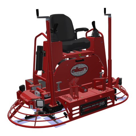
Toro 68048 User manual

FormNo.3374-232RevD
PT-36,PT-36PP ,PT-46,and
PT-46PPPowerTrowel
ModelNo.68048—SerialNo.313000001andUp
ModelNo.68049—SerialNo.313000001andUp
ModelNo.68050—SerialNo.313000001andUp
ModelNo.68051—SerialNo.313000001andUp
g019403
Registeratwww.Toro.com.
OriginalInstructions(EN)*3374-232*D

WARNING
CALIFORNIA
Proposition65Warning
Thisproductcontainsachemicalorchemicals
knowntotheStateofCaliforniatocausecancer,
birthdefects,orreproductiveharm.
Theengineexhaustfromthisproduct
containschemicalsknowntotheStateof
Californiatocausecancer,birthdefects,
orotherreproductiveharm.
ThissparkignitionsystemcomplieswithCanadianICES-002.
Becauseinsomeareastherearelocal,state,orfederal
regulationsrequiringthatasparkarresterbeusedonthe
engineofthismachine,asparkarresterisavailableas
anoption.Ifyourequireasparkarrester,contactyour
AuthorizedToroServiceDealer.
GenuineTorosparkarrestersareapprovedbytheUSDA
ForestryService.
Important:ItisaviolationofCaliforniaPublic
ResourceCodeSection4442touseoroperatetheengine
onanyforest-covered,brush-covered,orgrass-covered
landwithoutasparkarrestermufermaintainedin
workingorder,ortheengineconstricted,equipped,and
maintainedforthepreventionofre.Otherstatesor
federalareasmayhavesimilarlaws.
Theenclosed
Engine Owner's Man ual
issuppliedfor
informationregardingtheUSEnvironmentalProtection
Agency(EPA)andtheCaliforniaEmissionControl
Regulationofemissionsystems,maintenance,and
warranty.Replacementsmaybeorderedthroughthe
enginemanufacturer.
Introduction
Thismachineisusedtocreateasmoothnishtoconcrete
slabs.
Readthisinformationcarefullytolearnhowtooperateand
maintainyourproductproperlyandtoavoidinjuryand
productdamage.Youareresponsibleforoperatingthe
productproperlyandsafely.
YoumaycontactTorodirectlyatwww .Toro.comforproduct
andaccessoryinformation,helpndingadealer,ortoregister
yourproduct.
Wheneveryouneedservice,genuineToroparts,oradditional
information,contactanAuthorizedServiceDealerorToro
CustomerServiceandhavethemodelandserialnumbersof
yourproductready.Figure1illustratesthelocationofthe
modelandserialnumbersontheproduct.Writethenumbers
inthespaceprovided.
1
G019402
Figure1
1.Locationofthemodelandserialnumbers
ModelNo.
SerialNo.
Thismanualidentiespotentialhazardsandhassafety
messagesidentiedbythesafetyalertsymbol(Figure2),
whichsignalsahazardthatmaycauseseriousinjuryordeath
ifyoudonotfollowtherecommendedprecautions.
Figure2
1.Safetyalertsymbol
Thismanualuses2wordstohighlightinformation.
Importantcallsattentiontospecialmechanicalinformation
andNoteemphasizesgeneralinformationworthyofspecial
attention.
©2013—TheToro®Company
8111LyndaleAvenueSouth
Bloomington,MN554202
Contactusatwww.Toro.com.
PrintedintheUSA
AllRightsReserved

Contents
Introduction..................................................................2
Safety...........................................................................4
SafeOperatingPractices...........................................4
SafetyandInstructionalDecals.................................5
ProductOverview..........................................................6
Controls................................................................6
Specications.........................................................8
Attachments/Accessories.........................................8
Operation.....................................................................8
CheckingtheEngineOilLevel..................................8
CheckingtheGearcaseOilLevel...............................9
CleaningDebrisfromtheMachine.............................9
FoldingandUnfoldingtheHandle.............................9
AddingFuel...........................................................10
StartingandStoppingtheEngine..............................11
OperatingtheMachine............................................12
Maintenance.................................................................13
RecommendedMaintenanceSchedule(s)......................13
PremaintenanceProcedures........................................13
DisconnectingtheSparkPlugWire...........................13
Lubrication...............................................................14
LubricatingtheBladeArms.....................................14
EngineMaintenance..................................................14
ServicingtheAirCleaner.........................................14
ServicingtheEngineOil..........................................15
ServicingtheGearcaseOil.......................................16
ServicingtheSparkPlug..........................................17
BeltMaintenance......................................................17
AdjustingtheBeltTension.......................................17
ControlsSystemMaintenance.....................................19
AdjustingtheTiltKnob..........................................19
AdjustingtheProPitchLinkageRod..........................19
TestingtheDyna-ClutchLever.................................19
AdjustingtheBlades...............................................20
AdjustingtheBladeArms........................................21
Storage........................................................................22
Troubleshooting...........................................................23
3

Safety
Improperuseormaintenancebytheoperatoror
ownercanresultininjury.Toreducethepotential
forinjury,complywiththesesafetyinstructionsand
alwayspayattentiontothesafetyalertsymbol,which
means
Caution
,
W ar ning
,or
Danger
—personalsafety
instruction.Failuretocomplywiththeinstructionmay
resultinpersonalinjuryordeath.
SafeOperatingPractices
Training
•ReadtheOperator’sManualandothertrainingmaterial.If
theoperator(s)ormechanic(s)cannotreadorunderstand
theinformation,itistheowner’sresponsibilitytoexplain
thismaterialtothem.
•Becomefamiliarwiththesafeoperationoftheequipment,
operatorcontrols,andsafetysigns.
•Alloperatorsandmechanicsshouldbetrained.The
ownerisresponsiblefortrainingtheusers.
•Neverletchildrenoruntrainedpeopleoperateorservice
theequipment.Localregulationsmayrestricttheageof
theoperator.
•Theowner/usercanpreventandisresponsiblefor
accidentsorinjuriesoccurringpeople,ordamageto
property.
Preparation
•Wearappropriateclothingincludingsafetyglassesand
hearingprotection.Longhair,looseclothing,orjewelry
maygettangledinmovingparts.
•Inspecttheareawheretheequipmentistobeusedand
removeallobjectswhichcanbecontactedbythemachine.
•Useextracarewhenhandlinggasolineandotherfuels.
Theyareammableandvaporsareexplosive.
–Useonlyanapprovedcontainer.
–Neverremovethegascaporaddfuelwiththeengine
running.
–Allowtheenginetocoolbeforerefueling.
–Donotsmoke.
–Neverfuelordrainthemachineindoors.
•Checkthattheoperatorpresencecontrols,safetyswitches,
andshieldsareattachedandfunctioningproperly.Donot
operateunlesstheyarefunctioningproperly.
Operation
•Onlyoperateingoodlight,keepingawayfromholesand
hiddenhazards.
•Besurealldrivesareinneutralbeforestartingengine.
•Neveroperatewithouttheshields,covers,orotherguards
securelyinplace.
•Donotchangetheenginegovernorsettingoroverspeed
theengine.
•Stoptheequipmentandinspectthebladesafterstriking
anobjectorifanabnormalvibrationoccurs.Make
necessaryrepairsbeforeresumingoperation.
•Keephandsandfeetawayfromthebladearea.
•Donotoperatethemachineundertheinuenceof
alcoholordrugs.
•Lightningcancausesevereinjuryordeath.Iflightning
isseenorthunderisheardinthearea,donotoperate
themachine;seekshelter.
•Useextremecarewhenloadingorunloadingthemachine
intoatrailerortruck.
MaintenanceandStorage
•Waitforallmovementtostopbeforeadjusting,cleaning,
orrepairing.Stopthemachine,stoptheengine,and
disconnectthespark-plugwire.
•Cleandebrisfromtheblades,drives,mufer,andengine
tohelppreventres.Cleanupoilorfuelspillage.
•Lettheenginecoolbeforestoringanddonotstorenear
ame.
•Shutoffthefuelwhilestoringortransportingontrailers.
Donotstorefuelnearamesordrainindoors.
•Parkthemachineonlevel,hardground.Neverallow
untrainedpersonneltoserviceit.
•Keepallpartsingoodworkingconditionandallhardware
tightened.Replaceallwornordamageddecals.
4

SafetyandInstructionalDecals
Safetydecalsandinstructionsareeasilyvisibletotheoperatorandarelocatednearanyareaofpotential
danger.Replaceanydecalthatisdamagedorlost.
93-9084
1.Liftpoint2.Tie-downpoint
117–2718
117–4979
1.Entanglementhazard,belt—keepawayfrommovingparts;
keepallguardsandshieldsinplace
125–4933
1.Warning—readthe
Operator’sManual.
4.Chokinghazard—donot
runtheengineinan
unventilatedarea.
2.Warning—wearhearing
protection.
5.Explosionhazard—stop
theengineandextinguish
allamesbeforerefueling.
3.Warning—keep
bystandersawayfrom
themachine.
125–4934
1.ReadtheOperator’s
Manual.
3.Engageclutch
2.Disengageclutch
125–4935
Models68049and68051only
1.Lowertheblades2.Raisetheblades
5

ProductOverview
1
2
3
4
g019519
5
2
4
1
g020316
Figure3
1.Handle-adjustmentknob4.Dyna-Clutchlever
2.Throttlehandle5.Tilt-adjustmentknob
(Models68048and68050
only)
3.ProPitchhandle(Models
68049and68051only)
1
2
3
4
5
7
g021560
6
Figure4
1.Liftingpoint5.Sedimentcup
2.Fuel-tankcap6.Recoil-starterhandle
3.Chokelever7.EngineOn/Offswitch
4.Fuelvalve
Controls
Recoil-starterHandle
Pulltherecoil-starterhandletostarttheengine(Figure4).
FuelValve
Closethefuelvalvewhentransportingorstoringthemachine
(Figure4).
ChokeLever
Usethechokelever(Figure4)tostartacoldengine.Before
pullingtherecoil-starterhandle,movethechokelevertothe
closedposition.Oncetheengineisrunning,movethechoke
levertotheopenposition.
Note:Awarmenginerequireslittleornochoking.
EngineOn/OffSwitch
TheOn/Offswitch(Figure4)allowstheoperatorofthe
machinetostartandstoptheengine.Thisswitchislocated
onthefrontoftheengine.RotatetheOn/Offswitchtothe
Onpositiontostartandruntheengine.RotatetheOn/Off
switchtotheOffpositiontostoptheengine.
6

ThrottleHandle
Pullthethrottlehandle(Figure3)toincreasetheenginespeed,
andpushthehandletodecreasetheenginespeed.Turnthe
handleclockwisetolockthethrottleataspecicspeed.Turn
thehandlecounterclockwisetounlockthethrottle.
Handle-adjustmentKnob
Turntheknobcounterclockwisetoloosenandmovethe
handletothedesiredposition.Turntheknobclockwiseto
tightenandlockthehandleinplace(Figure3).
Dyna-ClutchLever
MovetheDyna-Clutchlever(Figure5)totheOnposition
(up)toallowthebladestorotate.MovethelevertotheOff
position(down)tostoptheblades.Intheeventthatthe
operatorreleasesthehandlewhilethebladesareturning,the
centrifugalforcefromtheswingofthehandlewillthrowthe
clutchlevertotheStopposition.
g019978
RUN
STOP
DYNA CLUTCH
1
Figure5
1.Dyna-Clutchlever
ProPitchTMHandle
Models68049and68051only
Pullthehandletoincreasetheangleofthebladestothe
concrete.Pressthetripbuttontoreleasethelock,andpush
thehandletodecreasetheangleoftheblades.
2
1
G019367
Figure6
1.Tripbutton2.Handle
Tilt-adjustmentKnob
Models68048and68050only
Turntheknobclockwisetoincreasetheangleoftheblades
(Figure6).Turntheknobcounterclockwisetoattenor
decreasetheangleoftheblades.
1
g021559
Figure7
1.Tilt-adjustmentknob
7

Specications
Note:Specicationsanddesignaresubjecttochange
withoutnotice.
Models68048and6804968050and68051
Width92cm(36.5inches)117cm(46inches)
Length(operating)177cm(70inches)190.5cm(75
inches)
Height(operating)99cm(39inches)99cm(39inches)
Weight102kg(225lbs)112kg(245lbs)
Attachments/Accessories
Aselectionofapprovedattachmentsandaccessoriesare
availableforusewiththemachinetoenhanceandexpand
itscapabilities.ContactyourAuthorizedServiceDealeror
Distributororgotowww.Toro.comforalistofallapproved
attachmentsandaccessories.
Operation
Note:Determinetheleftandrightsidesofthemachine
fromthenormaloperatingposition.
CheckingtheEngineOilLevel
ServiceInterval:Beforeeachuseordaily
Themachinecomesfromthefactorywithoilintheengine
crankcase,however,itmaybenecessarytoaddoil.Addonly
enoughoiltoraisetheleveltotheFullmarkonthedipstick;
refertoServicingtheEngineOil(page15).
OilType:4-cycleengineoilthatmeetsorexceedsthe
requirementsforAPIservicecategorySJ,SL,SM,orhigher
ModelsCrankcaseCapacity
68048and680490.58L(0.61USqt)
68050and680511.1L(1.2USqt)
Important:Iftheoillevelinthecrankcaseistoolow
ortoohighandyouruntheengine,youmaydamage
theengine.
Note:UseSAE10W-30forgeneraluse.Youcanuse
theotherviscositiesshowninthechartwhentheaverage
temperatureinyourareaiswithintheindicatedrange(Figure
8).
g013375
0 20 40 60 80 100 F
-20 -10 0 10 20 30 40 C o
o
30
5W - 30 / 10W - 30
Figure8
1.Stopthemachineonalevelsurface.
2.SettheDyna-ClutchlevertotheStopposition,stop
theengine,waitforallmovingpartstostop,andturn
offtheengineswitch.
3.Cleanaroundthedipstick(Figure9)sothatdirtcannot
fallintothellportanddamagetheengine.
8

12
3
4
G019746
Figure9
1.Fillport3.Oil-levelupperlimit
2.Dipstick4.Oil-levellowerlimit
4.Unscrewthedipstickandwipetheendclean(Figure9).
5.Slidethedipstickfullyintothellport(Figure9)
withoutthreadingitintotheport.
6.Removethedipstickandlookattheend.Iftheengine
oillevelislow ,slowlypouronlyenoughoilintothell
porttoraisetheleveltotheFullmarkonthedipstick
(Figure9).
7.Installandsecurethedipstick.
CheckingtheGearcaseOil
Level
ServiceInterval:Beforeeachuseordaily
1.Stopthemachineonalevelsurface.
2.SettheDyna-ClutchlevertotheStopposition,stop
theengine,andwaitforallmovingpartstostop.
3.Lookatthesightglassinthegearcaseplug(Figure10).
Theoillevelshouldbe3/4full.
g021590
Figure10
Iftheoillevelisnotcorrect,refertoServicingtheGearcase
Oil(page16).
CleaningDebrisfromthe
Machine
ServiceInterval:Beforeeachuseordaily
1.SettheDyna-ClutchlevertotheStopposition,stop
theengine,waitforallmovingpartstostop,andturn
offtheengineswitch.
2.Brushdirtanddebrisawayfromtheaircleanerand
engineopenings.
FoldingandUnfoldingthe
Handle
1.Turnthehandle-adjustmentknobcounterclockwise
toloosenthehandle.
2.Placethehandletothedesiredpositionandturn
thehandle-adjustmentknobclockwisetotightenthe
handle(Figure11).
9

1 32 G019366
Figure11
1.Handlefullyextended3.Handlefolded
2.Handle-adjustmentknob
AddingFuel
•Forbestresults,useonlyclean,fresh,unleadedgasoline
withanoctaneratingof87orhigher((R+M)/2rating
method).
•Oxygenatedfuelwithupto10%ethanolor15%MTBE
byvolumeisacceptable.
•Donotuseethanolblendsofgasoline(suchasE15
orE85)withmorethan10%ethanolbyvolume.
Performanceproblemsand/orenginedamagemayresult
whichmaynotbecoveredunderwarranty.
•Donotusegasolinecontainingmethanol.
•Donotstorefueleitherinthefueltankorfuelcontainers
overthewinterunlessafuelstabilizerisused.
•Donotaddoiltogasoline.
DANGER
Incertainconditions,gasolineisextremely
ammableandhighlyexplosive.Areorexplosion
fromgasolinecanburnyouandothersandcan
damageproperty.
•Fillthefueltankoutdoors,inanopenarea,
whentheengineiscold.Wipeupanygasoline
thatspills.
•Neverllthefueltankinsideanenclosedtrailer.
•Donotllthefueltankcompletelyfull.Add
gasolinetothefueltankuntilthelevelis6to13
mm(1/4to1/2inch)belowthebottomofthe
llerneck.Thisemptyspaceinthetankallows
gasolinetoexpand.
•Neversmokewhenhandlinggasoline,andstay
awayfromanopenameorwheregasoline
fumesmaybeignitedbyaspark.
•Storegasolineinanapprovedcontainerand
keepitoutofthereachofchildren.Donotbuy
morethana30-daysupplyofgasoline.
•Donotoperatewithoutentireexhaustsystemin
placeandinproperworkingcondition.
DANGER
Incertainconditionsduringfueling,static
electricitycanbereleasedcausingasparkwhich
canignitethegasolinevapors.Areorexplosion
fromgasolinecanburnyouandothersandcan
damageproperty.
•Alwaysplacegasolinecontainersontheground
awayfromyourvehiclebeforelling.
•Donotllgasolinecontainersinsideavehicleor
onatruckortrailerbedbecauseinteriorcarpets
orplastictruckbedlinersmayinsulatethe
containerandslowthelossofanystaticcharge.
•Whenpractical,removegas-poweredequipment
fromthetruckortrailerandrefueltheequipment
withitswheelsontheground.
•Ifthisisnotpossible,thenrefuelsuch
equipmentonatruckortrailerfromaportable
container,ratherthanfromagasolinedispenser
nozzle.
•Ifagasolinedispensernozzlemustbeused,
keepthenozzleincontactwiththerimofthe
fueltankorcontaineropeningatalltimesuntil
fuelingiscomplete.
10

UsingFuelStabilizer/Conditioner
Useafuelstabilizer/conditionerinthemachinetokeepthe
fuelfreshduringstorageof90daysorless.Ifyouarestoring
themachineforlonger,drainthefueltank;refertoStorage
(page22).
Important:Donotusefueladditivescontaining
methanolorethanol.
Addthecorrectamountoffuelstabilizer/conditionertothe
fuel,andfollowthedirectionsofthemanufacturer.
Note:Fuelstabilizer/conditionerismosteffectivewhen
mixedwithfreshfuel.Tominimizethechanceofvarnish
depositsinthefuelsystem,usefuelstabilizeratalltimes.
FillingtheFuelTank
ModelsFuelTankCapacity
68048and680493.1L(0.82USgallons)
68050and680515.3L(1.40USgallons)
1.SettheDyna-ClutchlevertotheStopposition,stop
theengine,waitforallmovingpartstostop,andturn
offtheengineswitch.
2.Allowtheenginetocool.
3.Cleanaroundthefuel-tankcapandremoveit(Figure
12).
Note:Thecapistetheredtothefueltank.
G020679
1
Figure12
1.Maximumfuellevel
4.Addunleadedgasolinetothefueltankuntilthelevelis
atthebottomofthemaximumfuellevel(Figure12).
Important:Theextraspaceinthetankallowsthe
fueltoexpand.Donotllthefueltankcompletely
full.
5.Installthefuel-tankcapsecurely.
6.Wipeupanyfuelthatmayhavespilled.
StartingandStoppingthe
Engine
StartingtheEngine
1.SetthethrottletofullrpmandsettheDyna-Clutch
levertotheStopposition.
2.MovetheengineswitchtotheOnpositionandturn
onthefuelvalve.
3.Movethechokelevertotheleftifyouarestartinga
coldengine.
Note:Awarmorhotenginemaynotrequirechoking.
4.Pulltherecoil-starthandleslowlyuntilyoufeelsome
resistance,thenpulltheitsharplytostarttheengine.
5.Aftertheenginestarts,graduallymovethechoketothe
right.Iftheenginestallsorhesitates,movethechoke
leftagainuntiltheenginewarmsup.
11

6.Movethethrottlelevertodesiredsetting.
StoppingtheEngine
1.Turntheengineswitchandfuelvalveoff.
2.Waitforallmovingpartstostopbeforeproceeding.
OperatingtheMachine
Important:Usethemachineonconcretethathasnot
setcompletely,butensurethattheconcretehasset
enoughtosupporttheweightofthemachine.
1.Starttheengine.
2.Aftertheenginehaswarmedup,adjustthethrottleto
approximatelyhalfspeed.
3.Adjustthebladestothedesiredangle.
•Foroating,setthebladesat(paralleltothe
ground),butwithsometensiononthecable.
•Fornishing,setthepitchofthebladesto
approximately6to9mm(1/4to3/8inches),or
approximately5to10degrees.
4.Holdthehandlermlywith1hand,andmovethe
Dyna-ClutchlevertotheOnpositiontostartthe
movementoftheblades.
5.Guidethetrowelovertheconcreteinacircular
back-and-forthmotion.
Note:Ifthebladesstarttodigintotheconcrete
decreasetheamountofthepitch.
6.SettheDyna-ClutchlevertotheOffposition,waitfor
anymovingpartstostopmoving,andstoptheengine;
refertoStoppingtheEngine(page12).
12

Maintenance
RecommendedMaintenanceSchedule(s)
MaintenanceService
IntervalMaintenanceProcedure
Aftertherst25hours•Changetheengineoil.
Beforeeachuseordaily
•Checktheengineoillevel.
•Checkthegearcaseoillevel.
•Cleandebrisfromtheaircleanerandengine.
•Lubricatethebladearms.
•Inspecttheaircleanerelements.
•Checkthebelttension.
•Checkforloosefasteners.
Every50hours•Cleantheairlterelements.Cleanthemmorefrequentlyindustyoperating
conditions.
Every100hours•Changetheengineoil.
•Inspectandadjustthesparkplug;replaceitifnecessary.
Every150hours•Changethegearcaseoil.
Every200hours•Replacethesparkplug.
Every300hours•Replacethepaperaircleanerelement.Replaceitmorefrequentlyindustyoperating
conditions.
Yearlyorbeforestorage•T ouchupchippedpaint
Premaintenance
Procedures
DisconnectingtheSparkPlug
Wire
Beforeperforminganymaintenanceontheengine,belts,or
blades,disconnectthesparkplugwirefromthesparkplug
(Figure13).
g019430
1
Figure13
1.Spark-plugwire
13

Lubrication
LubricatingtheBladeArms
ServiceInterval:Beforeeachuseordaily
GreaseType:General-purposegrease.
1.Cleanaroundeachgreasettingwitharagandliftthe
plasticcapoffeachgreasetting.
2.Pumpseveralshotsofgreaseintoeachttinguntilit
startstooozeoutofthebearing(Figure14andFigure
15).
Important:Pumpgreaseinslowlyandcarefully
topreventdamagetothebearingseals.
g019383
Figure14
g019396
Figure15
3.Wipeupanyexcessgrease.
EngineMaintenance
ServicingtheAirCleaner
ServiceInterval:Beforeeachuseordaily—Inspecttheair
cleanerelements.
Every50hours—Cleantheairlterelements.Clean
themmorefrequentlyindustyoperatingconditions.
Every300hours/Yearly(whichevercomes
rst)—Replacethepaperaircleanerelement.Replace
itmorefrequentlyindustyoperatingconditions.
Important:Donotoperatetheenginewithouttheair
lterassembly;extremeenginedamagewilloccur.
1.SettheDyna-ClutchlevertotheStopposition,stop
theengine,andwaitforallmovingpartstostop.
2.Disconnectthewirefromthesparkplug.
3.Removethenutthatsecurestheaircleanercover
(Figure16BoxA).
G019679
g019680
AB
CD
Figure16
14

4.Removethecover(Figure16BoxB).
Note:Becarefultopreventdirtanddebrisfrom
fallingintothebase.
5.Removethefoamandpaperelementsfromthebase
(Figure16BoxC).
6.Removethefoamelementfromthepaperelement
(Figure16BoxD).
7.Inspectthefoamandpaperelements,andreplacethem
iftheyaredamagedorexcessivelydirty.
Note:Nevertrytobrushdirtoffthepaperelement;
brushingforcesthedirtintothebers.
8.Cleanthefoamelementinwarm,soapywaterorina
nonammablesolvent.
Note:Donotusegasolinetocleanthefoamelement
becauseitcouldcreateariskofreorexplosion.
9.Rinseanddrythefoamelementthoroughly.
10.Dipthefoamelementincleanengineoil,thensqueeze
outtheexcessoil.
Note:Excessoilinthefoamelementrestrictstheair
owthroughtheelementandmayreachthepaper
lterandclogit.
11.Wipedirtfromthebaseandthecoverwithamoistrag.
Note:Becarefultopreventdirtanddebrisfrom
enteringtheairductleadingtothecarburetor.
12.Installtheaircleanerelementsandensurethattheyare
properlypositioned.
13.Securelyinstallthecoverwiththenut.
ServicingtheEngineOil
OilType:4-cycleengineoilthatmeetsorexceedsthe
requirementsforAPIservicecategorySJ,SL,SM,orhigher
ModelsCrankcaseCapacity
68048and680490.58L(0.61USqt)
68050and680511.1L(1.2USqt)
Important:Iftheoillevelinthecrankcaseistoolow
ortoohighandyouruntheengine,youmaydamage
theengine.
Viscosity:UseSAE10W-30forgeneraluse.Youcanuse
theotherviscositiesshowninthechartwhentheaverage
temperatureinyourareaiswithintheindicatedrange(Figure
8).
g013375
0 20 40 60 80 100 F
-20 -10 0 10 20 30 40 C o
o
30
5W - 30 / 10W - 30
Figure17
ChangingtheEngineOil
ServiceInterval:Aftertherst25hours
Every100hours
WARNING
Oilmaybehotaftertheenginehasbeenrun,and
contactwithhotoilcancauseseverepersonalinjury.
Avoidcontactingthehotengineoilwhenyoudrain
it.
1.Movethemachinetoalevelsurface.
2.SettheDyna-ClutchlevertotheStopposition,stop
theengine,andwaitforallmovingpartstostop.
3.Disconnectthewirefromthesparkplug.
4.Placeapanunderthedrainplugtocatchtheoil.
5.Removethedrainplug(Figure18).
1
g019417
Figure18
1.Drainplug
6.Replacetheplugwhentheoilhasdrainedcompletely.
Note:Disposeoftheusedoilatacertiedrecycling
center.
7.Removethedipstick(Figure9)andslowlypouroilinto
thellholeuntiltheoilpoursoutofthellhole.
8.Installandsecurethedipstick.
9.Wipeupanyspilledoil.
15

ServicingtheGearcaseOil
ServiceInterval:Every150hours
OilType:80W-90
gear oil
thatmeetsorexceedsAPI
servicecategory
GL-5
.
Capacity:1.18L(1.25USqt)
1.SettheDyna-ClutchlevertotheStopposition,stop
theengine,andwaitforallmovingpartstostop.
2.Disconnectthewirefromthesparkplug.
3.Placeapanunderthedrainplugtocatchtheoil.
4.Removethegearcaseplug(Figure18).
1
g021574
Figure19
1.Gearcaseplug
5.Tipthemachineanddraintheoilcompletelyoutof
thegearcase.
Note:Disposeoftheusedoilatacertiedrecycling
center.
6.Returnthemachinetoanupright,levelposition.
7.Placea3.8cm(1-1/2inch)blockunderthestationary
bladeguard(outerring)sothatthesideofthegearbox
withtheplugisapproximately6mm(1/4inch)higher
thantheothersideofthegearbox.
8.Slowlypouroilintotheplugholeuntiltheoilreaches
thethreadsofthehole.
Note:Ifnecessary,useaexiblefunnel.
9.Applythread-sealingcompoundtothethreadsofthe
plug.
10.Installandtightenthepluguntilitissecure,andreturn
themachinetoanupright,levelposition.
Note:Theoillevelinthesightglassoftheplugshould
be3/4full(Figure20).
g021590
Figure20
16

ServicingtheSparkPlug
ServiceInterval:Every100hours—Inspectandadjustthe
sparkplug;replaceitifnecessary.
Every200hours—Replacethesparkplug.
UseanNGKBPR6ESsparkplugorequivalent.
1.SettheDyna-ClutchlevertotheStopposition,stop
theengine,andwaitforallmovingpartstostop.
2.Disconnectthewirefromthesparkplug.
3.Cleanaroundthesparkplug.
4.Removethesparkplugfromthecylinderhead.
Important:Replaceacracked,fouled,ordirty
sparkplug.Donotcleantheelectrodes,because
gritenteringthecylindercandamagetheengine.
5.Setthegapontheplugto0.76mm(0.030inch);refer
toFigure21.
G019300
1 2 4
3
Figure21
1.Sideelectrode3.Insulator
2.Centerelectrode4.0.76mm(0.030inch)gap
6.Carefullyinstallthesparkplugbyhand(toavoidcross
threading)untilitishandtight.
7.Tightenthesparkpluganadditional1/2turnifitis
new;otherwise,tightenitanadditional1/8to1/4turn.
Important:Aloosesparkplugcanbecomevery
hotandcandamagetheengine;overtighteninga
sparkplugmaydamagethethreadsinthecylinder
head.
8.Connectthewiretothesparkplug.
BeltMaintenance
AdjustingtheBeltTension
ServiceInterval:Beforeeachuseordaily
g019382
1
2
3
4
5
Figure22
1.Belttensionpulley4.Enginepulley
2.Belt5.Gearboxpulley
3.Beltguide
RemovingtheBelt
1.Stopthemachineonalevelsurface,placethe
Dyna-ClutchleverintheStopposition,stoptheengine,
anddisconnectthesparkplugwire.
2.Removethe2hex-washerheadboltsthatsecurethe
beltguardtothebelt-guardbrackets.
3.Removethebeltguard.
4.Slipthebeltoffthebelt-tensionpulley(Figure22).
5.Slipthebeltoffthegearboxpulley.
6.Slipthebeltofftheenginepulleyandremovethebelt.
17

AligningthePulleys
1.Placeastraightedgeruleracrosstheenginepulleyand
thegearboxpulley(Figure22).
2.Ifthepulleysareoutofalignmentperformthe
following:
A.Loosenthe2setscrewsthatsecuretheengine
pulleytotheengineshaft.
B.Gentlytaptheenginepulleytowardorawayfrom
theengineuntilthegearboxandenginepulleys
aligntothestraightedgeruler.
C.Tightenthe2setscrewsthatsecuretheengine
pulleytotheengineshaft.
AdjustingtheBelt
1.PlacetheDyna-ClutchleverintheRunposition.
2.Measuretheairgapbetweenthebeltandthebeltguide
(Figure23).
g020708
2
3
1
Figure23
1.Ruler3.Belt
2.Beltguide
Theairgapshouldbeapproximately6mm(1/4inch).Ifan
adjustmentneedstobedone,performthefollowing:
1.Loosentheboltthatsecuresthebeltguidetothe
engineplate.
2.Whilekeepingthetopofthebeltguideparalleltothe
belt,movethebeltguidetowardorawayfromthebelt
untiltheairgapiscorrect.
3.Tightentheboltthatsecuresthebeltguidetothe
engineplate.
AdjustingtheTensionPulley
Adjustthetension-pulleyspringasneededtotightenthebelt.
1.MovetheDyna-ClutchlevertotheStopposition.
2.Adjustthecontrolcableasneededtotightentheslack
inthebelt(Figure24).
g019369
12
34
Figure24
1.Tensionspring3.Cable-housingbracket
2.Controlcable4.Locknuts
3.Loosentherearlocknutofthecontrolcable.
4.Loosenortightentheforwardlocknuttoaddpullto
thetensionspringtotightenthebelt.
5.Tightentherearlocknutofthecontrolcable.
18

ControlsSystem
Maintenance
AdjustingtheTiltKnob
1.SettheDyna-ClutchlevertotheStopposition,stop
theengine,andwaitforallmovingpartstostop.
2.Disconnectthewirefromthesparkplug.
3.Attachanoverheadlifttotheliftingpointonthe
machineandliftitoffoftheground.
4.Turnthetiltknobuntilthereisenoughcableslackto
accessthetiltlocknut(Figure25).
g019446
1
2
3
4
5
6
7
8
9
1.63
Figure25
1.Tiltknob6.Nut
2.Bearing7.Tiltblock
3.Tiltrod8.Tiltcable
4.Tiltlocknut9.Setscrew
5.Washer
5.Tightenthelocknutagainstthebearingthenloosenit
slightly.Setitwiththesetscrew(Figure25).
6.Adjustthenutsinsidethetiltblocktotakeupanycable
slack.
Note:Replacethecablesiffulltiltisnolongerobtainable.
AdjustingtheProPitchLinkage
Rod
1.SettheDyna-ClutchlevertotheStopposition,stop
theengine,andwaitforallmovingpartstostop.
2.Disconnectthewirefromthesparkplug.
3.Attachanoverheadlifttotheliftingpointonthe
machineandliftifoffoftheground.
4.Loosenthenutontheupperendofthelinkagerodto
allowslackintheliftcable(Figure26).
2
3
5
6
4
g019445
1
Figure26
1.Nut4.Linkagerod
2.Swivel5.Nut
3.Nut6.Yokeend
5.PositiontheProPitchhandleinthefulltiltposition.
6.Adjustthenutonthebacksideoftheswivelatthe
upperendofthelinkageroduntilyouachievethe
propergapofapproximately0.4mm(1/64inch)
betweenthetiltleverandthegearcase.
7.Tightenthenutontheoutsideoftheswiveltolockthe
linkagerodintoposition.
TestingtheDyna-ClutchLever
TestingtheDyna-ClutchOperation
Ensurethattheareaisclearofanydebrisorbystanders
beforebeginningthetestingprocedures.
1.Startthetrowel,engagetheDyna-Clutchlever,andrun
themachineforafewmoments.
2.MovetheDyna-ClutchlevertotheStopposition.
3.Watchthebladesforanysignofcontinuedrotation.
Ifthebladesdonotstop,thereistoomuchtension
onthecableandspring.Stoptheengineanddecrease
theamountoftensiontoallowtheDyna-Clutchlever
todisengagecompletely.
19

Ensurethatthereisstillenoughtensiononthecableand
springtopreventpartsfromcomingunhookedduring
operation.Ifthetendencyforthebladestorotatewhenthe
Dyna-Clutchleverisdisengagedcannotbeadjustedoutofthe
systemwithouttakingalltensionoffofthecableandspring,
carefullyinspectthedrivebeltandDyna-Clutchleversystem
forwearordamage.Ensurethatallpartsareoperatingfreely.
IftheDyna-Clutchleverdoesnotstoptheblades,seean
AuthorizedServiceDealer.
TestingtheDyna-ClutchLever
Adjustment
EnsurethatthetestingoftheDyna-Clutchleverisdoneis
aclearandopenarea.
1.MovetheDyna-ClutchlevertotheStopposition.
2.Startthetrowel.
3.Turnoffthefuelvalve.
4.HoldontothehandleandengagetheDyna-Clutch
lever.
5.Letgoofthehandle.
TheDyna-ClutchlevershouldswitchtotheStop
positionwithin1rotation.Ifitdoesnot,keepclearof
theareaandwaitforthemachinetorunoutoffuel.
Bringthemachinetoanauthorizedservicelocation.
AdjustingtheBlades
Adjustthebladestoremoveexcessiveshakingofthemachine.
1.Disconnectthesparkplugwireandmovethe
Dyna-ClutchlevertotheStopposition.
2.Place3or4blocksofequalheightunderthestationary
bladeguard(outerring)toraisethebladesoffofthe
oor.
Note:Ensurethattheblocksareclearoftheblades
sothatthebladescanberotatedwithouttouchingthe
blocks.
1
2G019516
Figure27
1.Stationarybladeguard2.Block
3.Measurefromtheoortotheleadingedgeofthe
blade.Notethemeasurement.
4.Placeamarkonthebladeandonthespotontheoor
fromwherethemeasurementwastaken(Figure28).
1
2
3
g019517
Figure28
1.Spotontheoorwherethe
measurementwastaken
3.Blade
2.Ruler
5.Rotatethebladesuntilthenextbladeisinthesame
positionasthepreviouslymeasuredblade.
6.Measurethesecondbladefromthespotpreviously
markedontheoortothesecondbladesleadingedge
(Figure29).
20
This manual suits for next models
7
Table of contents
Popular Trowel manuals by other brands

SCANMASKIN
SCANMASKIN Scan Helicopter manual
MULTIQUIP
MULTIQUIP Whiteman series Operation manual
Husqvarna
Husqvarna CRT 48-35L Operator's manual
MULTIQUIP
MULTIQUIP Whiteman JWN Series Operation and parts manual

Superabrasive
Superabrasive LAVINA LP36GE user manual
allen
allen Hydra-Drive Extreme Series Operation and parts manual
