Crommelins CPT24S Administrator Guide

1
CROMMELINS™ POWER TROWELS
Thank you for your selection of a CROMMELINS™ Power Trowel.
This Operation Manual explains its use, installation, checking and maintenance.
We highly recommend that you retain this manual for ready reference regarding
proper handling of the CROMMELINS™ Power Trowel.
Spare Parts & Service
Phone: 1300 554 524
Freecall Fax: 1800 636 281
spareparts@crommelins.com.au
www.crommelins.com.au
WA Metro 9350 5588
WA Regional 1800 655 588
East Coast 1300 650 659
OPERATION & INSTRUCTION MANUAL

2
Thank you very much for purchasing a CROMMELINS™ POWER TROWEL.
This manual covers operation and maintenance of the CROMMELINS™ POWER TROWEL.
This CROMMELINS™ POWER TROWEL can be used in the mining, construction, hire
industries and general use.
Please take a moment to familiarise yourself with the proper operation and maintenance
procedures in order to maximise the safe and efficient use of this product.
Keep this owner’s manual at hand, so that you can refer to it at anytime.
Due to constant efforts to improve our products, certain procedures and specifications
are subject to change without notice.
When ordering spare parts please have handy your products model number and serial
number. Record these numbers in the boxes below for future reference.
Please fill in the following blanks after checking the production number and serial
number on your product. (The location of these numbers, vary depending on product).
CONTENTS
Introduction & Contents ...................................................................................... 2
Safety Precautions & Belt Setting ....................................................................... 3
Pre Start-up Checking .......................................................................................... 4
Operation ........................................................................................................... 5
Shutdown & Maintenance .................................................................................. 6
Storage ................................................................................................................. 7
Specifications Charts .......................................................................................... 8-9
Trouble Shooting ................................................................................................. 10
Power Trowel Diagram ........................................................................................ 11
Power Trowel Parts List ........................................................................................ 12
Power Trowel Reducer Diagram .......................................................................... 13
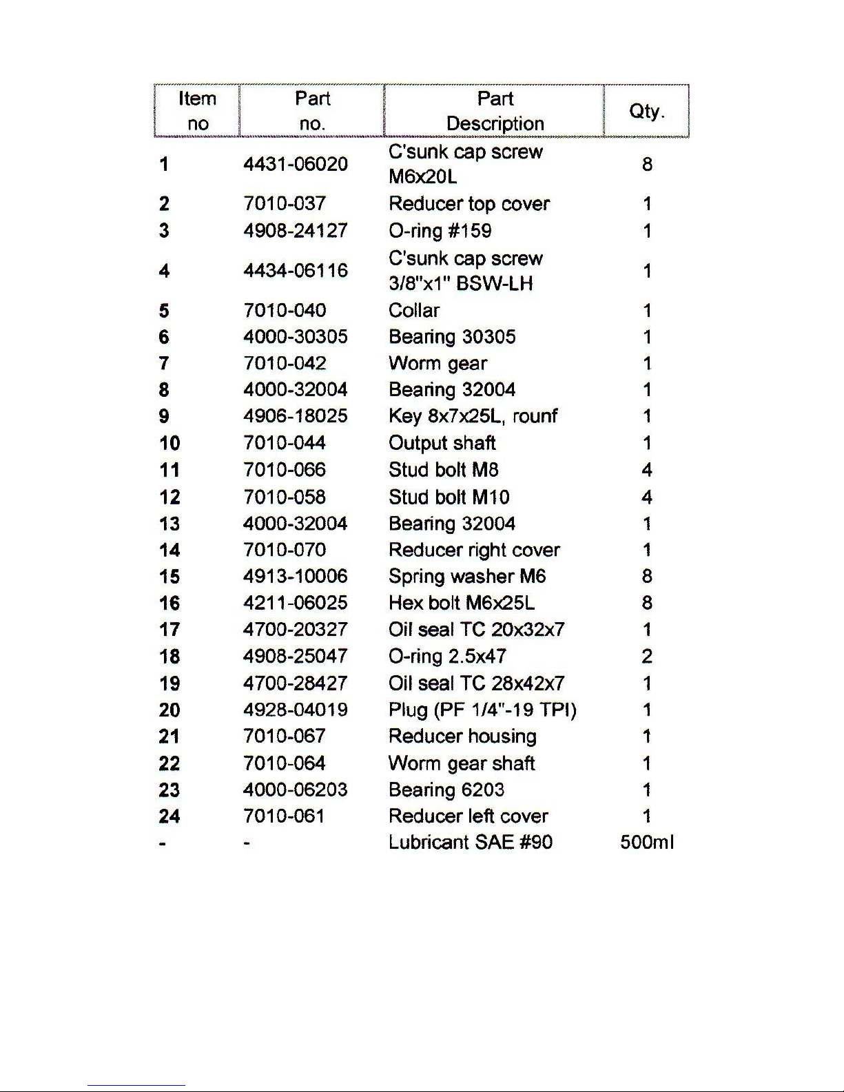
Power Trowel Reducer Parts List .......................................................................... 14
Power Trowel Spider Diagram ............................................................................ 15
Power Trowel Spider Parts List ............................................................................ 16
SERIAL NO.
MODEL NO.

3
This manual contains important information on how to use the following power trowels
models CPT24S, CPT34R, CPT34RD, CPT40R, CPT40RD and CPT46S properly and safely.
Please read through this manual before you attempt to operate this product.
SAFETY PRECAUTIONS
Before operating this piece of equipment, the operator should read this manual.
Whenever possible, he/she should be shown how to operate the unit by an experienced
operator. It is dangerous for an inexperienced person to operate any machine. Trial and
error is not the safe way to become familiar with a piece of equipment.
To prevent injury wear the following protective clothing: Gloves, hard hat, work boots, ear
plugs, safety goggles and any other protective devices required by job conditions.
•Stay AWAY from blades during operation.
•Be cautious with the ventilation of work place. Avoid operating machine in closed
area, since engine exhaust contains poisonous gases.
•Be careful with hot components. Mufflers and other parts of the engine are hot during
operation and right after shutdown.
•Fasten fuel cap tightly and close fuel strainer cock during transportation.
BELT SETTING
STEP 1 –Loosen engine base bolt (underneath engine) to allow engine-base movement.
STEP 2 –Insert V-belt into clutch pulley and reducer pulley one at a time.
STEP 3 –Adjust the engine position by moving engine-base to ensure v-belts are tight
enough.
IMPORTANT: Normal slack should be approximately 10-15mm (1/2”) when the belts are
forcibly depressed in the middle position between rotor pulley and clutch pulley.
Tighten all engine bolts and cover V-belt and pulley with belt cover, tighten cover bolts.

4
PRE START-UP CHECKING
•Consult engine manual for detailed starting information.
•Check all bolts and screws for tightness. Loose bolts and screws may cause damage to
the unit.
•Make sure that all dirt, mud, etc., are thoroughly removed from areas such as cooling air
inlet of engine, carburettor, and air cleaner.
•Check V-belt tightness. The normal slack should be approximately 10-15mm (1/2”) when
the belts are forcibly depressed in the middle position between two pulleys. To set belt
tightness; refer to Belt Setting at page 3.
•Check fuel level and refill as required.
•Check engine oil level. If engine oil level is low, refill it with the correct engine oil as
stated in the engine manual.
CAUTION! –Make sure nobody is in the vicinity of the trowel when starting the engine; it
might move suddenly with force.
STARTING (PETROL UNITS)
STEP 1 –Open engine fuel cock.
STEP 2 –Set throttle lever to starting position.
STEP 3 –For cold engine starting, close carburettor choke lever.
STEP 4 –Set engine switch to “ON”.
STEP 5 –Pull recoil starter.
IMPORTANT: Do not pull recoil starter rope to the end as it may cause damage. When the
rope is pulled out, release the rope slowly. Do not let the rope snap back.
STEP 6 –After engine starts, open the choke halfway and warm up the engine for 2-3
minutes with low speed position. The warm up procedure should particularly be
followed during cold weather.
STARTING (DIESEL UNITS)
STEP 1 –Set speed control to low speed.
STEP 2 –Pull recoil starter rope until resistance is felt.
STEP 3 –Bracing foot against engine, pull recoil starter rope with both hands.
IMPORTANT: Do not pull recoil starter rope to the end as it may cause damage. When the
rope is pulled out, release the rope slowly. Do not let the rope snap back.

5
OPERATION
CAUTION! –Poisonous fumes. Start and operate only in a well-ventilated area. Be careful
with hot components, mufflers and other engine parts are hot during operation. Do not
touch them.
STEP 1 –Adjust throttle lever to the desired speed.
STEP 2 –Follow the pattern illustrated below during operation.
-Smooth partially set floor surface; operate the machine with blades
fattened. For a luster finish, operate with the blades slightly tiled. Over tilted
blades on unset floor with create a wavy surface.
-Floor that has completely set is difficult to smooth. If this is the case, tilt
blades as high as possible. Sprinkle water on the floor beforehand.

6
SHUTDOWN –PETROL UNIT
STEP 1 –Move throttle lever to low speed position quickly and run engine for 2-3 minutes
at low speed.
STEP 2 –Turn of the stop switch, the engine stops completely.
STEP 3 –Close engine fuel cock.
STEP 4 –Cover the machine after the muffler has cooled off and keep the trowel in a dry
place.
EMERGENCY SHUTDOWN: Move throttle lever to OFF and press engine stop button.
SHUTDOWN –DIESEL UNIT
STEP 1 –Move throttle lever to low speed position quickly and run engine for 2-3 minutes
at low speed.
STEP 2 –Move the throttle lever to the stop position.
STEP 3 –Cover the machine after the muffler has cooled off and keep the trowel in a dry
place.

7
MAINTENANCE
CAUTION!
FLAMMABLE LIQUID. When performing maintenance, stop engine and do not smoke in
adjacent area.
HIGH TEMPERATURE. Allow machine and engine to cool down before performing
maintenance. Contact with hot components can cause serious injury.
MOVING PARTS. Make sure engine is shutdown before maintenance. Contact with moving
parts can cause serious injury.
Daily Service
•Wash blades and rotary parts with water before any adhered concrete hardens. Then
dry thoroughly and apply grease or oil on them.
•Constantly check for any lose screws, nuts and bolts; retighten any loose parts.
•Grease spider blade assembly (4 x nipples) with Castrol EPL2 or equivalent.
Weekly Service (every 50 hours of operation)
•Refer to engine service manual.
Reduction Gear Maintenance
•Lubricating oil in reduction gear should be changed after the first 50 hours and 250
hours of operation; and at every 1000 hours of operation thereafter.
•Following oil is recommended for reduction gear –USE SAE 140 GEAR OIL.
•Spray lubricant onto cable pulley and adjuster slide.
STORAGE
Storing for a long period
•Thoroughly drain the fuel from the fuel tank, fuel pipe and carburettor.
•Pour a few drops of motor oil into the cylinder by removing the spark plug. Rotate the
engine several times by hand so that the cylinder interior is covered with oil.
•Clean the outer surface of the machine with an oil-moistened cloth. Cover the unit and
store in a humidity-free, dust-free area.

8
POWER TROWEL SPECIFICATION CHART
MODEL
CPT24S
CPT34R
CPT34RD
Weight (kg)
50kg
75kg
75kg
Engine Make
Subaru
Subaru
Subaru
Engine
4.5hp EX13
6.0hp EX17
4.8hp DY23
Engine Features
OHC
OHC
OHV
Fuel Type
Petrol
Petrol
Diesel
Fuel Tank
2.7L
3.6L
3.2L
Noise Level db@7m
64.0
66.0
74.0
Manufacturers Warranty
2 yrs
2 yrs
2 yrs
Engine Warranty
3 yrs
3 yrs
3 yrs
Trowel Size
24” (610mm)
34” (860mm)
34” (860mm)
Overall WxLxH (mm)
660x1460x980
932x1700x1000
1080x1700x1000
Blade Diameter
610mm
860mm
1016mm
Blade Dimensions
225x120
195x325
200x376
Quantity of Blades
4
4
4
Blade Revolution (RPM)
50 - 100
50 - 100
50 - 100

9
POWER TROWEL SPECIFICATION CHART
MODEL
CPT40R
CPT40RD
CPT46S
Weight (kg)
78kg
93kg
102kg
Engine Make
Subaru
Subaru
Subaru
Engine
6.0hp EX17
4.8hp DY23
9.0hp EX27
Engine Features
OHC
OHV
OHC
Fuel Type
Petrol
Diesel
Petrol
Fuel Tank
3.6L
3.2L
6.1L
Noise Level db@7m
66.0
74.0
70.0
Manufacturers Warranty
2 yrs
2 yrs
2 yrs
Engine Warranty
3 yrs
3 yrs
3 yrs
Trowel Size
40” (1016mm)
40” (1016mm)
46” (1170mm)
Overall WxLxH (mm)
1080x1700x1000
1080x1700x1000
1155x1775x1000
Blade Diameter (mm)
1016
1016
1170
Blade Dimensions (mm)
200x376
200x376
195x480
Quantity of Blades
4
4
4
Blade Revolution (RPM)
50 - 100
50 - 100
50 - 100

10
TROUBLE SHOOTING GUIDE
If the power trowel malfunctions immediately shut the machine down. Following are
some simple trouble shooting tips:
PROBLEM
CAUSE
SOLUTION
Engine stops suddenly
or does not run
1. No fuel in the engine
2. Spark plug carbonised
3. Containment is being
snagged up to fuel
strainer
1. Refill Fuel
2. Clean spark plug
3. Clean fuel strainer
Machine is slow or
erratic
1. Loose V-belt
1. Adjust V-Belt (refer to belt
installation and setting)
Engine runs but the
machine does not
1. Clutch slip
1. Disassemble clutch and clean
it, then reassemble
IF THE FAULT PERSISTS, CONTACT YOUR LOCAL DEALER.

11
POWER TROWEL PARTS DIAGRAM

12
POWER TROWEL PARTS LIST

13
POWER TROWEL REDUCER DIAGRAM
14
POWER TROWEL REDUCER PARTS LIST
15
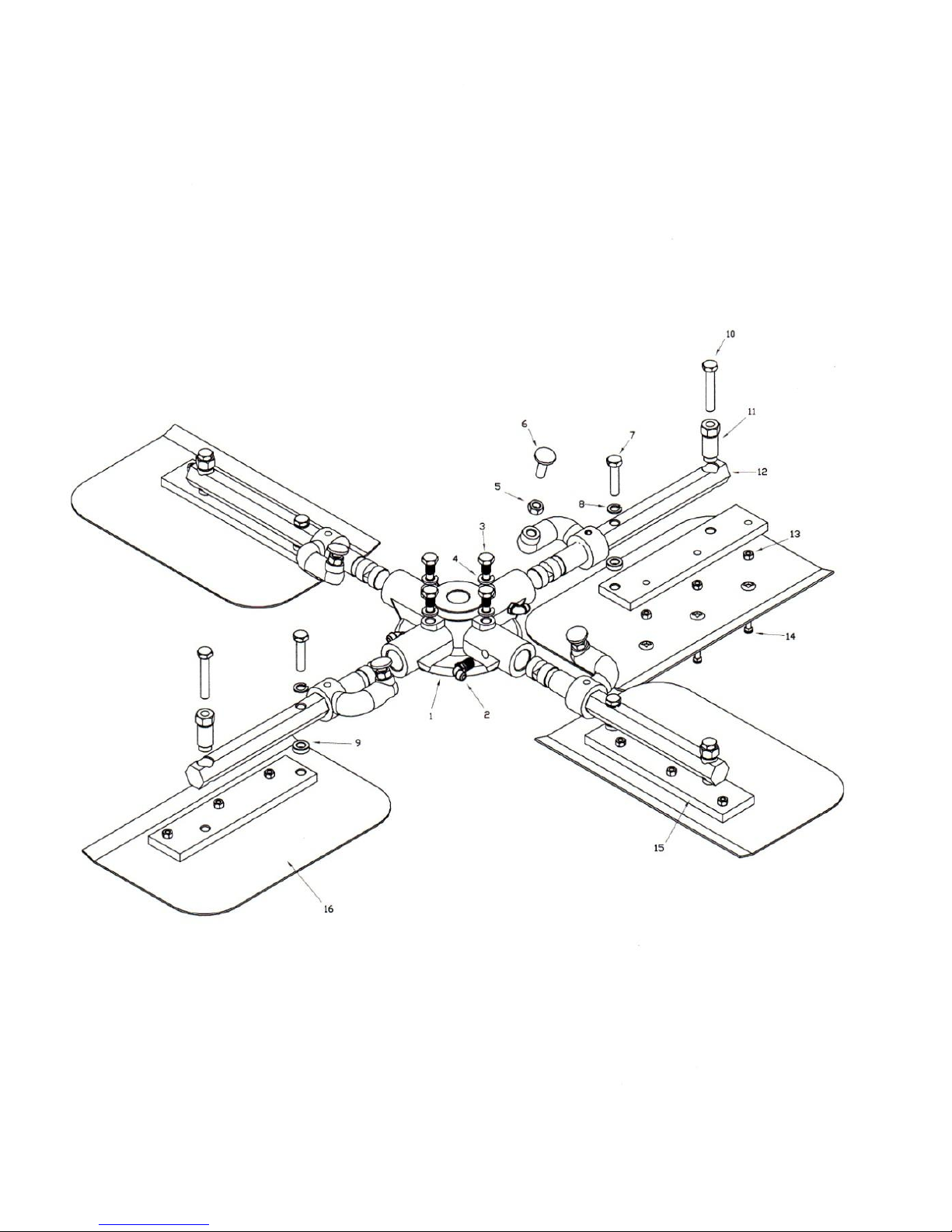
POWER TROWEL SPIDER DIAGRAM
16
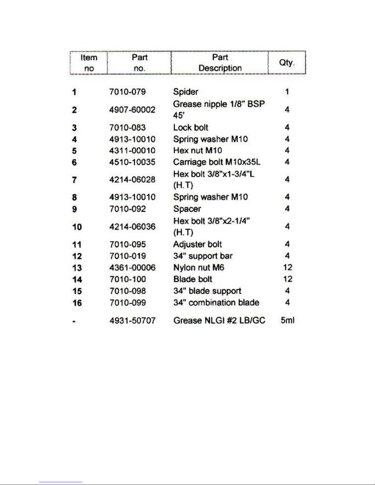
POWER TROWEL SPIDER PARTS LIST
16 CPT70140SET 40” Blade Set (Qty 4) 1
16 CPT70146SET 46” Blade Set (Qty 4) 1
This manual suits for next models
5
Table of contents


