TORONTO TOOL Pro-Cut 50 User manual
TORONTO TOOL MANUFACTURING INC.
Pro-Cut 50
User Manual
Pro-Cut 50 User Manual Version 03:02:115:04
The contents of this manual are subject to change without notice. For any updates or improvements please visit our web
site at: www.torontotool.com

1
Pro-Cut 50 User Manual
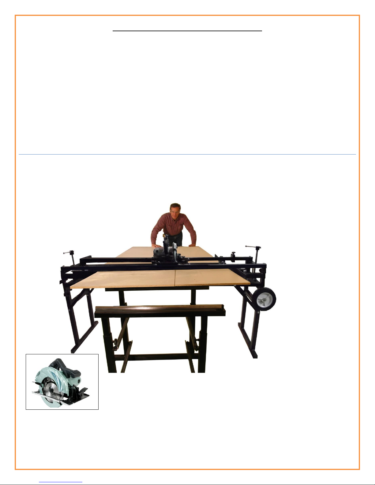
Pro-Cut 50 (Professional Table Saw and Router System)
Thank you for purchasing the Pro-Cut 50 (Professional Table Saw and Router System). Below you will find
Safety Procedures, set-up procedures and operating instructions. For video demonstrations, be sure to visit
the “How To” section of our web site www.torontotool.com
Canadian Made, Professional Grade Products
It’s time for a change! Introducing the Pro-Cut 50 Professional Table Saw and Router System!Conventional table
saws have been around for years and have been virtually unchanged from the original design. There are a number of
challenges when using a conventional table saw that many people have struggled with and tried to improve over the
years. A conventional table saw is good for rip cutting boards and panels, but depends on the operator to feed material
evenly and tight against the side fence to produce straight cuts. You also have to ensure the material is held down on
the table top so it doesn’t “ride the blade” while feeding. This is true more so with thinner material such as ¼” plywood.
A conventional table saw also relies on the side fence clamping exactly parallel to the blade. If the side fence is not
parallel to the blade, the resulting cut will have excessive “tear out” and also greatly increases the possibility “kick back”.
The fact that a side fence moves means it will have some play and a good possibility of error.
Next Generation Table Saw
The new Pro-Cut 50 is the next generation table saw with numerous features and benefits to address the inherent
disadvantages of a table saw. The Pro-Cut 50 rip cuts material like a conventional table saw but, unlike a conventional
table saw, the material is fully guided on both sides thus eliminating feed errors. The side fence is fixed at exactly 90o to
the saw thus eliminating any side fence error as can be experienced on conventional table saws. For cutting angles you
simply tilt the saw to any desired angle. The Pro-Cut 50 is based on Toronto Tool’s industrial design where the saw
moves along precision guide rails for cross cutting and locks to any position for rip cutting. The Pro-Cut 50 has adjustable
height for cutting material up to 3-1/2” thick. The smooth movement of the sled includes 8 sealed roller bearings and 4
industrial grade bearing blocks to ensure precision and accuracy of movement. Rip cutting narrow boards or full 4’ x 8’
panels has never been easier. A conventional table saw is prone to “kick back” due to design but the top mounted saw
of the Pro-Cut 50 encapsulates your material thus virtually eliminating the possibility of “kick back”. The Pro-Cut 50
comes standard with a top of the line, premium grade Hitachi PCC7BMR saw chosen for its quality of construction,
power and accuracy. You can also opt to up-grade to the C7YA saw with built in dust collection.

2
Cross Cutting Advantage
Cross cutting on a conventional table saw can be a challenge at the best of times and involves moving the entire piece of
material through the blade. An uneven feed while cross cutting can cause pinching of the material and most likely result
in “kick back”. A number of people build a cross cut sled for their table saw that rides in the small grove on the table top.
This method generally works for smaller panels and boards but does not work well for larger panels. A good number of
people don’t even attempt cross cutting large panels on their table saw. They resort to a guide and circular saw. Even if
you are fortunate enough to have a sliding cross cut table set up for your table saw, you still have to move the entire
sheet. In a lot of cases, the crosscut add-on costs more than the table saw itself and takes up a tremendous amount of
valuable floor space in your shop. Cutting wood across the grain in one pass will most likely produce chipping or tear
out. This can be minimized by using a quality finish blade with a high tooth count but still doesn’t eliminate “tear out”
and/or “chipping”. The only proven method for eliminating “tear out” or “chipping” is by kerf cutting. A pre-cut or kerf
blade is only found on the most expensive table saws.
A Different Approach
The Pro-Cut 50 uses an entirely different approach to crosscutting. The board or panel is locked in place on the Pro-Cut
50 and the saw slides through the material on precision guide rails. No more reaching over the panel or trying to hold a
panel square and tight against the side fence while also making sure to keep the panel flat on the table surface so it
doesn’t “ride the blade” and, at the same time, trying to feed it smoothly into the saw blade.
INCLUDED with the PRO-CUT 50
Hitachi PCC7BMR 7-1/4" Saw Featuring IDI
Technology
Powerful15 amp motor to tackle the toughest cutting jobs. Patented
IDI (Internal Double Insulation) technology reduces vibration and
extends tool life Bevel capacity adjustable from 0-55° with positive
stops at 45° and 55° Heavy duty die-cast aluminum base with
integrated scale provides stability and accuracy. Large all metal
leavers for adjusting depth and bevel angles. Electric brake stops the
blade quickly after the switch is released. Magnesium housing, gear
cover, blade cover and lower guard for increased strength and smooth
operation.
PRO-CUT 50
Professional Table Saw and Router Guide System
PCC7BM
R

3
The Pro-Cut 50 will eliminate “tear out” and “chipping” when cutting across the grain. Easily perform by kerf cutting a
board or panel for perfectly smooth cuts. Due to the precision guide system of the Pro-Cut 50, you simply raise the blade
of the saw to make a pre- cut (also known as a kerf cut) on the board or panel and then lower the blade to complete the
cut. The result is a perfectly smooth cut against the grain on both the top and bottom of any material including
hardwood, softwood, veneer panels and melamine.
The PRO-CUT 50
is also a full “X” and “Y” Router Table
Take full advantage of your router using the Pro-Cut 50
By simply unlocking and removing the saw from the Pro-Cut 50 sled and placing the router in its place, you have
instantly converted your Pro-Cut 50 from a precision table saw to a full size precision “X” & “Y” router table. The Pro-Cut
50 has the ability to rout in both the “X” and “Y” directions on all projects from something as small as a bread board
right up to 50” wide panels. Your material can be of any length in the “Y” direction. Perfect for making your own custom
moldings, window frames, small and large cabinet doors, custom table tops, picture frames, fluted rails just to name a
few. You can also dado both side panels of a cabinet at the same time on the Pro-Cut 50. This is perfect for exact
placement of shelves in cabinets of any height. Routing cutouts for inlays in any project is also a breeze on the Pro-Cut
50. The Pro-Cut 50 comes with the router insert plate, 2 router guide stops and 2 panel stops for quick and easy set-up
for routing any project. Virtually anything you can imagine can be made using the Pro-Cut 50. The router is top mounted
on the Pro-Cut 50 so you can always see the cut in progress. This is a huge advantage over a conventional router table
where the router is mounted underneath. A conventional router table is one dimensional and will only produce cuts in
one direction and is also limited in width of cut thus limiting the wide range of uses a router is capable of. The Pro-Cut
50 allows an operator to take full advantage of the router and the countless operations a router is able to perform. You
can even glue another board(s) or panel to the top of your project and continue routing. Great for making true raised
panel doors for example. The Pro-Cut 50 is designed for ease of use, precision and productivity for rip cutting,
crosscutting and all your router needs. The Pro-Cut 50 is also designed for easy storage when not in use with fold up legs
and wheels.
Available for the Pro-Cut 50
Hitachi Router kit KM12VC
PRO-CUT 50

4
For Your Own Safety Read Instruction Manual
Before Operating Tool
Save it for future reference
GENERAL SAFETY PRECAUTIONS
(For All Tools)
1. KNOW YOUR POWER TOOL. Read the 6. KEEP CHILDREN AWAY. All visitors
owner’s manual carefully. Learn the tool’s should be kept safe distance from work area.
applications and limitations, as well as the
specific potential hazards particular to it. 7. MAKE WORKSHOP KID PROOF with padlocks,
2. KEEP GUARDS IN PLACE and in working master switches, or by removing starter keys.
order.
3. REMOVE ADJUSTING KEYS AND 8. DON’T FORCE TOOL. It will do the job better
WRENCHES. Form habit of checking to and safer at the rate for which it was designed.
see that keys and adjusting wrenches are
removed from tool before turning it on. 9. USE RIGHT TOOL. Don’t force tool or
4. KEEP WORK AREA CLEAN. Cluttered attachment to do a job for which it was not designed.
areas and benches invite accidents.
5. DON’T USE IN DANGEROUS ENVIRONMENT. 10. WEAR PROPER APPAREL. Do not wear
Don’t use power tools in damp or loose clothing, gloves, neckties, rings,
wet locations, or expose them to rain. bracelets, or other jewellery which may get
Keep work area well lit. Don’t use caught in moving parts. Nonslip footwear
tool in presence of flammable liquids or is recommended. Wear protective hair
gases. covering to contain long hair. Always wear safety glasses.
SPECIFIC SAFETY RULES
DO NOT let comfort or familiarity with product (gained from
repeated use) replace strict adherence to safety
rules. If you use this tool unsafely or incorrectly, you can suffer
serious personal injury.
Always use a push stick to complete cuts. Never place fingers near the cutting blade under
any circumstances.
Setting up your Pro-Cut 50 Professional for the first time
When un-packaging your new Pro-Cut 50 please inspect all parts for damage and report any damage to
Toronto Tool Manufacturing Inc. right away.
The Pro-Cut 50 and Pro-Cut 50DC come fully assembled and adjusted at our facility however it is always good
practice to make a few test cuts to ensure the adjustments did not move during shipping. Adjusting the Pro-
Cut 50 is straight forward and will be discussed in detail later in this user guide.
There are basically two points to keep in mind during adjustment.
1) The sled slides freely along the guide rails with minimal side to side play.
2) The saw cuts at exactly 900 to the side fence when cross cutting.
The following diagrams show the different parts of the Pro-Cut 50 starting with the fold down leg assemblies
and securing the leg struts.

5
Release the leg lock levers, lift one end of the Pro-Cut 50 to fold down the leg assembly on one end of
the machine (Fig. 1b) making sure the leg assembly is resting tightly against the leg stops. A leg strut is
attached to each side of the leg assembly. A bolt and wing nut is located on the Pro-Cut 50 frame on
either side of the frame that the leg struts attach to. Remove the wing nut from the bolt along with the
washer on one side of the leg assembly. Fold the leg strut up to allow the drilled hole in the leg strut to
line up with the bolt on the frame. Insert the bolt into the leg strut, attach the washer and wing nut
and hand tighten. Follow the same procedure for the leg strut on the opposite side of this leg
assembly. Follow the same procedure for the leg assembly on the other end of the Pro-Cut 50.
Sled Guide Rail Sub Frame.
1) The Sled Guide Rail Sub Frames have a 5/8” x 14” Clamp Screw and 5/8” Clamp Screw Nut.
2) There are (2) knobs on either side of the Pro-Cut 50 Sub Frame (Fig 2). These are used to lock the Sled
Guide Rail Sub Frame in place after adjusting the height of the sled carriage.
3) Sled Guide Rail (Fig 3)
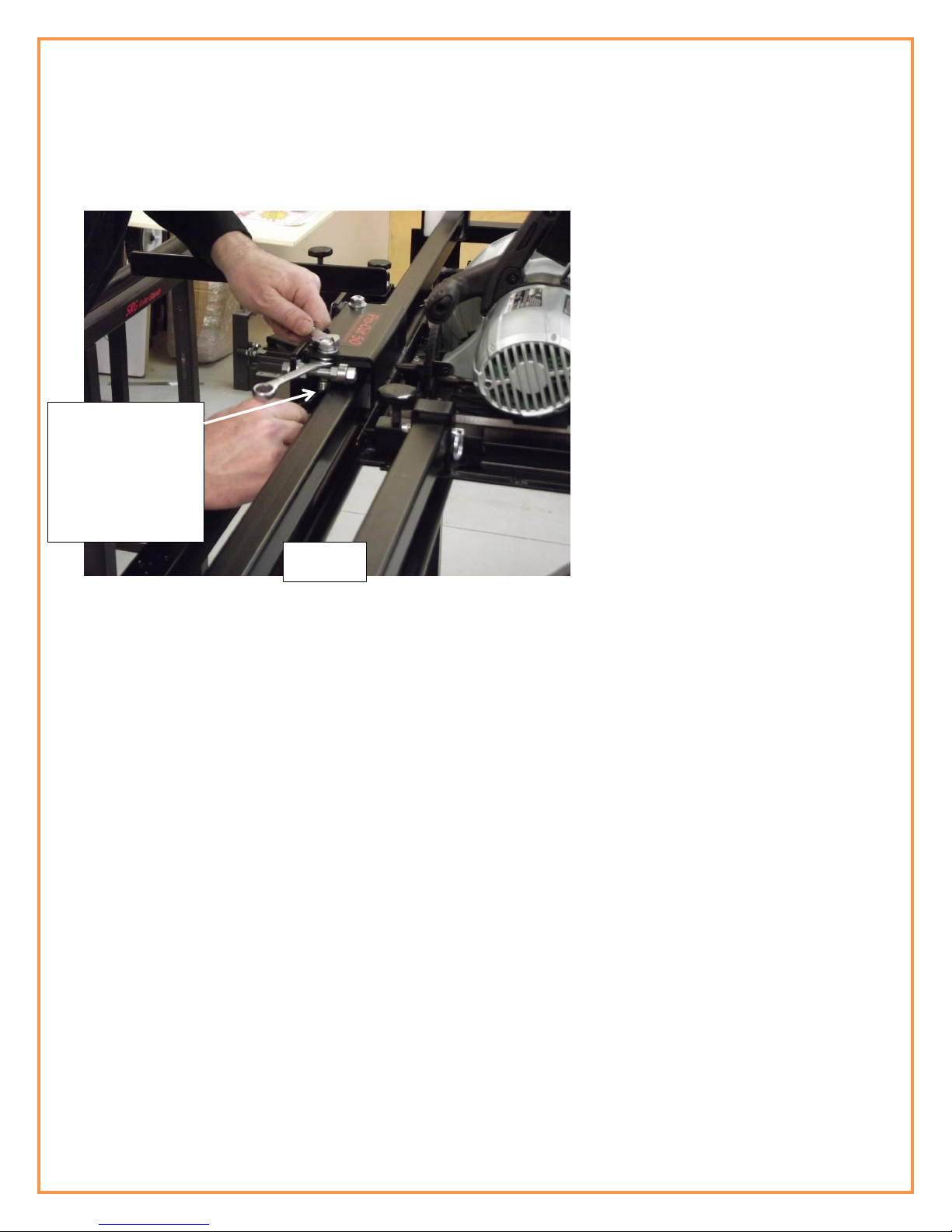
4) Clamp screw Nut (shown in Fig 2 &Fig 3). If it becomes necessary to tighten the clamp screw nut, use
an adjustable wrench and, holding the clamp screw handle, tighten the clamp screw nut onto the
Spacer
Washer
Fig 1
Fig 2
Fig 3
Fold down legs and lock
leg struts
Fig. 1a
Fig. 1b
6
clamp screw. Loosen the (2) frame knobs to raise and lower the guide rail sub frame using the clamp
screw. Carriage height adjustment and the use of spacers will be discussed later in this user guide.
Sled Guide Rails
(Fig 4 & 5) shows the Sled Guide Rail and Sled Guide Rail Bolts. There are 1” slots in the Sled Guide Rail Sub
Frame to allow independent adjustment of each Sled Guide Rail. The slots will be used to allow the exact
positioning of the Sled Guide Rails (explained later).
Side Fence
The side fence assembly has 4 adjustment points. The side fence base has two slots to allow squaring
of the entire side fence assembly to the saw blade (fig 6). The clamp rails have slots to allow alignment
of the side fence wings (Fig 7) explained later in this manual.
Fig 4
Side
Fence
Fig 5
Fig 6
Fig 7
Sled Guide Rail

7
Measuring scale
The Pro-Cut 50 and Pro-Cut 50 DC now come with a built in measuring scale mounted to the non-operator side
of the machine. The sled has a scale marker attached to it that moves along the top of the measuring scale.
When setting the machine up for rip cutting, simply slide the sled along the rails until you reach the desired
measurement as indicated by the sled scale marker. With the sled set at the desired measurement, lock the
sled in place using the 2 sled locks.
NOTE: All hand held tape measures are slightly different and can be out by as much as 1/16 to 1/8” from one
measuring tape to another. It is always good practice to use the same tape measure for all measurements
throughout your entire project. A common problem on most equipment with built in tape scales is that they do
not always measure the same as the hand held tape measure you are using and therefore a lot of seasoned
woodworkers never use built in scales on any equipment.
The Pro-Cut 50 allows an operator to adjust the entire measuring scale on the machine to exactly match your
hand held tape measure with one easy adjustment of the scale. Follow the steps below.
1) To make this adjustment only use the hand held tape measure you will use for your project. We will set
the scale on the Pro-Cut 50 to exactly match your hand held tape measure.
2) Set the saw sled (with the saw in the sled set in the rip cut position) at 15” as indicated on the built in
scale. With your hand held tape measure, measure from the outside tooth of the saw blade to the side
fence. If the measurement is identical, no adjustment is necessary. If the measurement is not the same
then loosen the two thumb screws on either end of the Pro-Cut 50 scale and move the entire scale
until the Pro-Cut 50 scale measurement is identical to the measurement on your hand held measuring
tape. Tighten the two thumb screws on the Pro-Cut 50 measuring scale. Your Pro-cut 50 scale is now
identical to your hand held scale.
Saw Blade Depth Gauge ……..IMPORTANT
To achieve the best results when cutting material with a minimum amount of tear-out and a smooth cut, it is
general practice in woodworking to set the saw blade depth no more than ¼” below the thickness of the
material you are cutting. With this in mind the new version of the Pro-Cut 50 has a built-in depth gauge rail
that will automatically set your saw blade to ¼” below the material you are cutting. (Fig C1 Page 26) shows the
depth gauge rail and (Fig C2 Page 26) shows the saw placed over the depth gauge rail.
Setting the saw blade depth is covered in greater detail in the section called Cross-Cutting starting on page 25.
To set the depth of your saw blade, raise the saw blade all the way up using the blade height adjustment on
the saw. Place the saw over the saw blade depth rail making sure the saw blade guard of the saw is covering
the blade. Lower the saw blade until the saw blade guard just touches and skims the surface of the depth
gauge rail on the Pro-Cut 50. The saw blade is now set to ¼” below the material you will cut. NOTE: always use
the depth gauge rail to set the saw blade depth to prevent cutting too deep into the table top and, in the
worst case scenario, cutting into the frame of the Pro-Cut 50.
The depth of the blade must be set to no more than ¼” below the material you are cutting for both cross
cutting and rip cutting. You will notice both a kerf cut and a grove are cut into the table top insert. The kerf cut
is ¼” deep and used for cross cutting. The grove is ¼” deep at the bottom of the grove and is used for rip
cutting.

8
For cross cutting set the blade depth using the depth gauge rail as explained above.
For rip cutting
1) Raise the saw blade height all the way up.
2) Move the saw to the desired position using the built in measuring scale.
3) Using the saw blade guard lever (Be sure the saw is unplugged) raise the saw blade guard to expose the
blade.
4) Lower the blade until the blade just touches the bottom of the grove in the table top insert.
5) Raise the saw blade slightly so it doesn’t scuff the grove and lock the saw blade height on the saw. You
are now ready to rip cut.
Aux Side Fence
The pro cut 50 comes with an Aux Side Fence used when rip-cutting material. It can also be used in
conjunction with your router. The Aux Side Fence takes the guess work out of feeding material
through the Pro-Cut 50. It acts like a giant feather board and keeps material tight against the side fence
and allows you to simply push the material though. In addition this method provides a smoother more
even cut without burns. The Aux Side Fence will not allow the board or panel to skew while feeding.
The Aux Side Fence has 2 heavy duty toggle clamps that clamp to the clamping rails of the Pro-Cut 50
frame. To set the Aux Side Fence, place your panel or board against the Pro-Cut 50 side fence and slide
the Aux Side fence up the opposite side of your board or panel. The Aux Side Fence should be placed
firmly against the side of your board or panel but not so tight as to restrict the smooth feed of the
material. Once you have the Aux Side Fence set, lock the 2 toggle clamps to the clamp rails of the Pro-
Cut 50 and you are ready to cut.
Pro-Cut 50 adjustment
This section will cover the adjustment of the Pro-Cut 50. Take your time with this procedure as it will
determine the accuracy of cut on the Pro-Cut 50.
There are only two key points to keep in mind when setting up the Pro-Cut 50.
a) That the sled moves back and forth smoothly with very little side to side play (do not worry about
making sure it is 90oto the side fence when setting up the sled. Only concentrate on getting the
sled moving back and forth smoothly and that it has very little side to side play).
b) After the sled is set up and running smoothly then adjust the side fence for square to the saw. This
is the step where you concentrate on making sure the saw blade is cutting exactly 90 degrees to
the side fence when cross-cutting.
The Pro-Cut 50 has a number of adjustment points listed below.
a) Both sled guide rails can be adjusted within the slots of the (2) guide rail sub frames. (Fig 4 &5)
b) The four sled roller bearings that ride on the sides of the guide rails can be adjusted to limit side to
side movement of the sled assembly within the guide rails. (the four sled roller bearings that ride
on top of the guide rails are fixed and do not require adjustment)
9
c) The saw can be adjusted for “skew” on the saw insert plate by loosening the 4 mounting bolts that
hold the saw to the insert plate. If necessary, you can adjust for Skew on the saw to the insert plate
and re-tighten the (4) mounting nuts and bolts. (This is one of the last procedures discussed later)
d) The side fence base is slotted to allow the side fence assembly to be adjusted for square to the saw
blade.
e) The adjustable “Side Fence Wing Locks”allow the side fence wings to be adjusted so they are
exactly in line with each other.
After adjustment, the sled should glide smoothly back and forth within the guide rails with virtually no side to
side “play”, the blade of the saw is running “true” and the saw cuts exactly 90o to the side fence in the cross
cut position.
ADJUSTMENTS
First we will focus on the sled and the sled guide rails. All we want to accomplish here is to make the
sled move back and forth smoothly on the guide rails and that the sled has very little side to side play
or wiggle.
For a complete set-up follow the steps listed below.
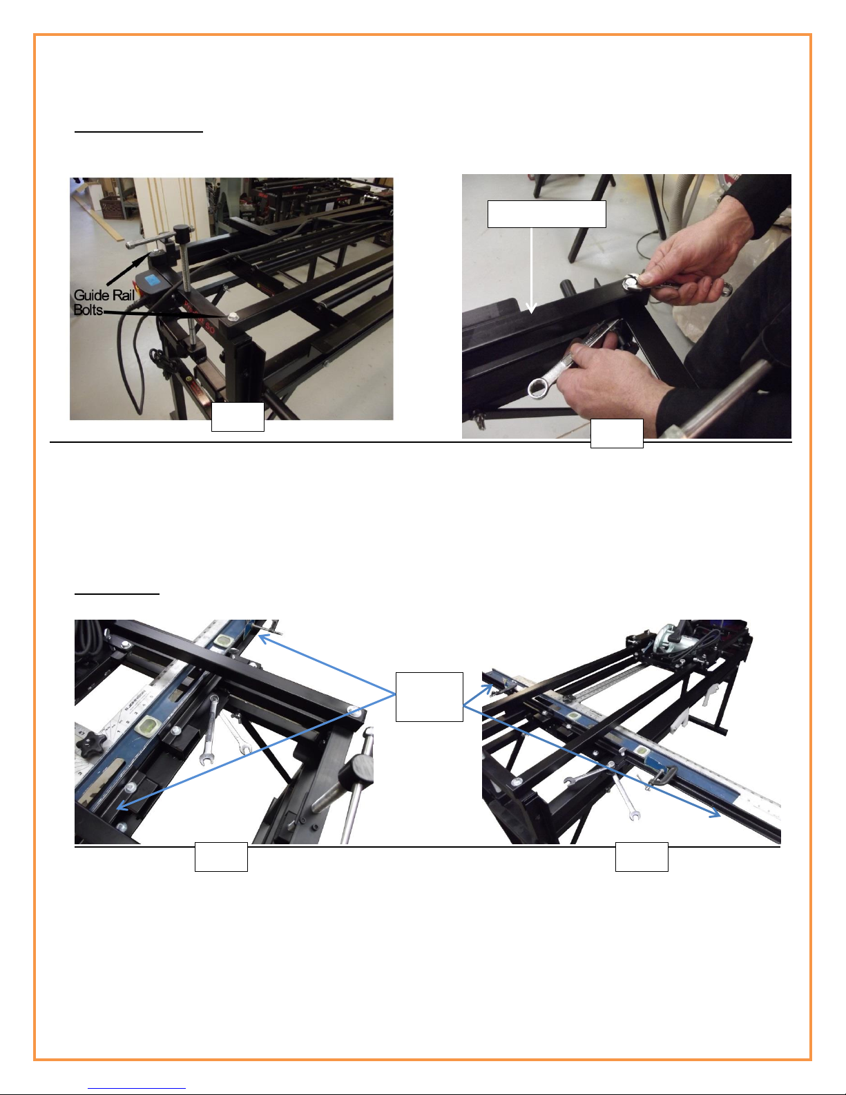
Loosen all 4 bolts holding both sled guide rails in place (Fig. 8a), loosen the 2 SIDE ROLLER bearings on
each side of the sled that ride against the sides of the sled guide rails (Fig 8b & Fig 8c below). There are
a total of 4 bearings to loosen. (Do not loosen the rollers that ride on top of the sled guide rail) (do not
worry about squaring at this point as that is taken care of in the last step). Start by adjusting the
operator side, sled guide rail first. This is the side opposite the measuring scale and the side you feed
material through for rip cutting.
Step1) Set-up only the “operator side” sled guide rail at this point. (Fig 8b) (the rest of the machine uses this
sled guide rail as the reference). This sled guide rail should measure 5/8" from the frame to the side of the sled
guide rail shown in (Fig. 8). When you are sure that the guide rail is 5/8" from the frame on both ends, tighten
the bolts on either end of this sled guide rail. Re-check your 5/8” measurement on both ends of the guide rail.
Fig 8
The measurement
from the guide rail to
the guide rail frame
should be equal on
both ends of the
guide rail.
Fig 8a
5/8”
One of the (4) Sled
Guide Rail Bolts
10
There are a total of 8 roller bearings located on the sled. 4 of the 8 roller bearings roll along the top of the sled
guide rail called the “TOP ROLLERS” (These roller bearing are fixed and do not require adjustment). The other
4 roller bearings roll against the sides of the sled guide rail called the “SIDE ROLLERS”. The 4 side roller
bearings determine how smooth the sled rolls back and forth and the side bearings also determine the
tolerance in the sled. The tighter you make the side roller bearings, the closer the tolerance but the more
resistance in pushing the sled. We generally set the sled up to 5 thousands of an inch tolerance. (Keep in mind
also there are 4 close tolerance bearing blocks inside the sled that work with the 4 side bearings. Be careful not
to “Pinch” the bearing blocks by adjusting the side roller bearings too tight).
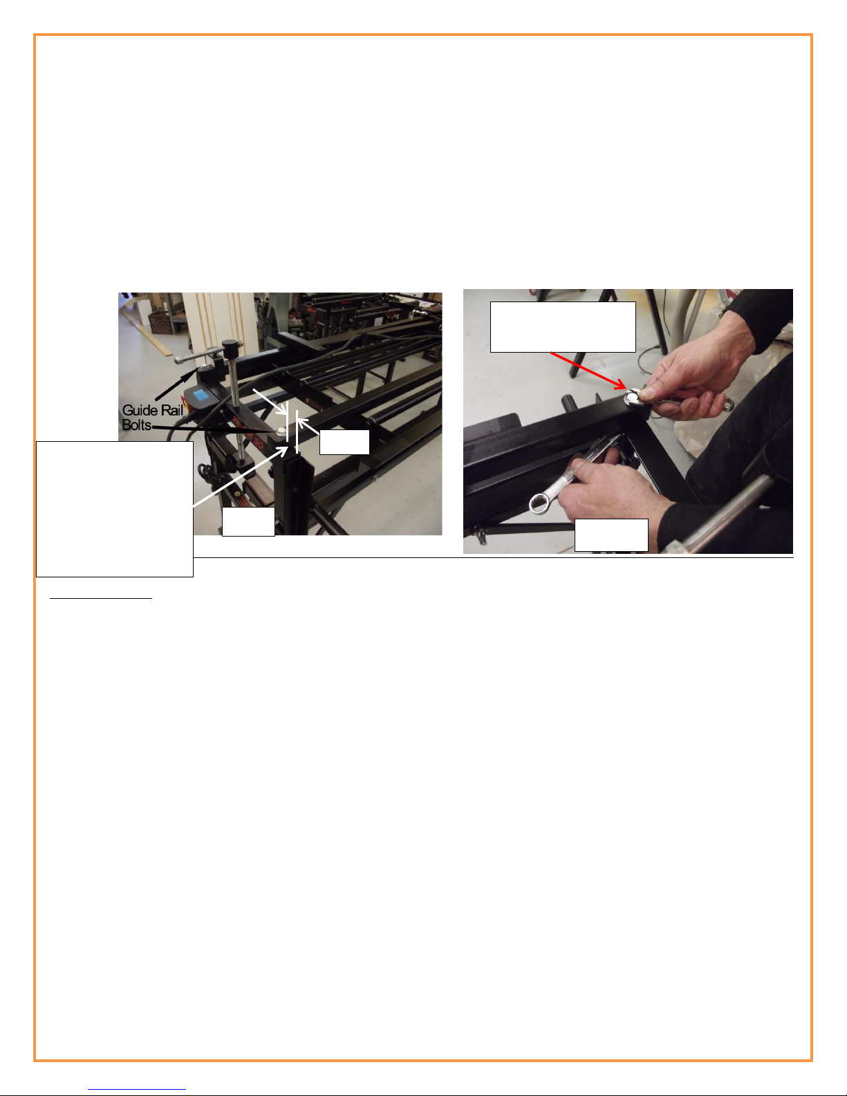
Step 2) Next we will adjust the (2) SIDE ROLLER bearings on the sled (Fig 8b) that roll against the sides of the
“Operator Side” sled guide rail that you just adjusted and bolted down tight. (Note the TOP roller bearings that
ride on top of the sled guide rails are pre-set and do not require adjusting)
Included with your machine were (2) white 1/2" spacers. Anything that is ½” thick will work fine. Place the 2
spacer blocks on the side of the sled between the frame of the sled and the “Operator Side” sled guide rail
(FIG. 8c). With the ½” spacers in place, lock the sled with the two black sled lock knobs, slide a SIDE ROLLER
bearing up against the side of the sled guide rail so it is snug against the sled guide rail (Fig 8c). Using (2) 9/16”
wrenches (one placed on the nut below, inside the sled, and one wrench placed on the top nut), tighten the
Side Roller Bearings
Top Roller Bearing
(Do Not Adjust)
“Operator Side”
Sled Guide Rail
Fig. 8b
½” spacer blocks
Use, two, 9/16”
wrenches
FIG 8c
Side Roller Bearings
Side Roller Bearings
Sled
Bearing
Block
Side Roller bearings

11
nuts on this roller bearing (Fig 8c). After tightening the side roller, the spacer block should be snug with
resistance when removing it but not so tight as it is difficult to remove. With both ½” spacers still in place, and
the sled still locked, follow the same procedure for the other SIDE ROLLER bearing on the other side of the sled
(Fig 8b & Fig 8c). Both spacers should now provide resistance when removing them but not so tight as to be
difficult to remove.
Now you have adjusted the operator side, sled guide rail and the 2 sled side bearings that run against the
operator side, sled guide rail. (Be sure the Bolts on the other sled guide rail are loose). Roll the sled back and
forth to be sure it moves freely. (Do not worry about the “play” in the sled at this point). The (2) roller bearings
on the other side of the sled will take care of the play. Run the sled back and forth from one end of the
machine to the other a few times. The white bearing blocks inside the sled will help adjust the other sled guide
rail.
Step 3) If you are satisfied the sled is moving freely, move on to adjusting the other sled guide rail. The
measurement between the inside of the “operator side” sled guide rail to the inside of the other sled guide rail
should be between 13 - 1/16” to 13 - 3/16” (Fig 8d). There can be some variance between machines but the
important point is to be sure the measurement between the sled guide rails is the same on both ends of the
machine. If you measure 13 - 1/16” on the inside of the guide rails on one end of the machine then the
measurement between the inside sled guide rails should be exactly 13 - 1/16” on the other end of the
machine. (NOTE: the corners of the sled guide rails are rounded so it is best to use a flat edge such as a steel
ruler to measure to). With both measurements exactly the same, tighten the sled guide rail bolts on both ends
of the sled guide rail making sure the guide rail does not move while you tighten the nuts and bolts. Re-Check
your measurement after the bolts are tight. Move the sled all the way back and forth a few times to ensure
the sled is moving freely. (NOTE: There will still be play in the sled as you move it back and forth at this point.
The next step will take care of this).
If the sled is difficult to move at one end but free on the other end then the distance between the guide rails
is not equal. Re-Check your measurement. (NOTE: There may be slight resistance in some points while moving
the sled back and forth. This is due to the powder coating on the guide rails. The inner bearing blocks will polish
the rails as you move it back and forth over time and the resistance will even out). To keep the guide rails clean
and polished, use a spray furniture polish or floor wax.
Measurement
adjusted to be
the same on
both ends.
Fig 8d
12
Step4) Adjusting the remaining 2 Sled Side Roller Bearings
1) At this point you have adjusted the operator side sled guide rail.
2) The sled side roller bearings on the operator side of the sled
3) The other sled guide rail.
We will now adjust the remaining (2) sled SIDE ROLLER bearings on the NON-operator side.
These are the roller bearings that will determine the amount of overall tolerance in the sled and adjust
for “play” or “wiggle” in the sled. The tolerance can be adjusted from one thousand of an inch to 10
thousands of an inch. We find that 5 thousands of an inch is perfect. (NOTE: the tighter you make the
tolerance the more resistance the sled will provide when moving it back and forth).
Place a 5 thousand inch feeler gauge between the (2) sled SIDE ROLLER bearings and the sled guide rail
Fig 8e). (NOTE: if you do not have a feeler gauge, one sheet of 20Lb bond paper compressed is
approximately one thousand of an inch. You can use 5 strips of paper). (NOTE: To make it easier, you
can tape the feeler gauge or paper to the sled guide rail until you have finished your adjustment).
Slide the side roller bearing snug up against the feeler gauge and tighten. Leave the feeler gauge in
place until you have adjusted the other side roller bearing in the same manor. With both side roller
bearings adjusted and tightened remove the feeler gauges and move the sled all the way back and
forth. At this point you should feel some resistance when moving the sled back and forth but it should
not be difficult to move.
To check for side to side play try to wiggle the sled. (NOTE: do not use the sled push rail to check for
side to side play as the push rail provides enough leverage to “Flex the guide rails)
If the sled is difficult to move back and forth after you have adjusted and tightened the two remaining
side roller bearings follow the steps below. You may have to make some slight adjustments to any one
of the 4 side roller bearings. (Note: a small adjustment of a roller bearing makes a big difference).
Place 5 thousand
feeler gauge
between the side
roller bearing and
the sled guide rail
Fig 8e
13
1) With your finger, try to move each of the (4) SIDE ROLLER bearings on the sled. The rollers should
move with some resistance. If you find that one of the bearings is impossible to move with your
finger but the other (3) seem to move okay then it will be necessary to adjust the side roller bearing
that will not move. In most cases this can be accomplished by simply loosening the bolt on the side
roller bearing, allowing it to self-adjust and then re-tighten the bolt.
2) If a side roller is easy to move at one end of the rails but difficult to move at the other end of the
rail then this indicates the rails are not perfectly parallel to each other. Re-check the distance
between rails.
3) Keep in mind that the machine has 4 internal floating bearing blocks. These are the white blocks
inside the casing of the sled. The side roller bearings work with these bearing blocks to virtually
eliminate side to side wiggle. If a side bearing is too tight, it is possible to pinch the internal bearing
block and it will act like putting on the breaks.
4) When the machine sled is properly adjusted the sled should move back and forth with some
resistance. You should be able to move each of the (4) sled Side Roller bearings with your finger.
The internal white bearing blocks are called floating bearing blocks designed to move freely within
the sled housing. You should be able to slide each of the (4) sled internal white bearing blocks back
and forth within the sled housing with your finger.
5) There should be very little side to side play when you wiggle the sled.
Step 5) Adjusting the Side Fence for Square
In this step we will adjust the side fence so it is exactly 90o to the saw blade when cross cutting. (Note when
the saw is set up at exactly 90o for cross cutting, the saw will be automatically squared to the side fence for rip
cutting). (The router will also be set up to rout in both the “X” and “Y” directions) (NOTE: The newer version of
the Pro-Cut 50 has a 2 section side fence while the earlier version has a 3 section side fence. The adjustment
method is exactly the same for both versions)
Start by:
1) Loosen the (2) side fence locking bolts (Fig F1) (These are the bolts that hold the entire side fence assy.)
Loosen the wing stop locks (Fig F2) and move them all the way back away from the wings. (on the Pro-
Cut 50 with the 3 part side fence, (1) center section and (2) wings, loosen the lock bolt on each wing
lock assy. and screw the bolts on each wing stop assy all the way back to allow the wings to move
back). The wing lock assemblies will be adjusted later.
Side Fence Bolts
Level
Clamped to
side fence.
“T” square
Against
Level

14
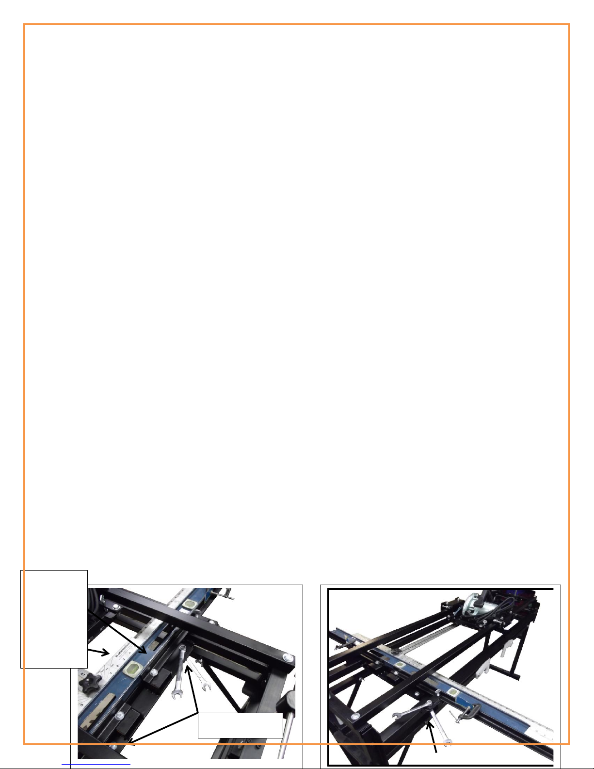
2) Place a long straight edge against the (2) side fence wings and clamp the straight edge to the side fence
wings using “C” clamps. For the straight edge you can use a 4’ level as shown in (Fig 8f) or any straight
edge that will accomplish the same thing. The idea is to clamp a straight edge to the side fence wings
to make it one it one complete fence to allow for easier squaring. (The side fence locks will be adjusted
later).
1) With the side fence wings clamped to a straight edge move the entire side fence assembly until it is close to
square to the saw blade.
2) Slide only one wing lock up to the wing and tighten the wing lock bolt to the clamping rail of the Pro-Cut 50
frame. Also tighten the thumb screw that locks the wing in place. With the side fence wings still clamped to the
straight edge and the one wing lock bolted in place, we will now fine tune for square to the saw blade. The
entire side fence will pivot on the one tightened wing lock to bring the entire side fence into square with the saw
blade.
3) Place the “T” of a large “T” square against the level as shown in (Fig 8f). Move the saw back and forth against
the “T” square. The saw blade should not deviate from the “T” square and you should hear a slight “scrapping”
sound for the full length of travel.
(NOTE: It may be easier to make this adjustment if you remove the sled push handle).
(TIP: the saw blade guard on the saw must be out of the way for this adjustment. Be sure the saw is
unplugged and place an elastic band over the saw blade guard lever and loop it over a locking knob on
the sled. This will hold the saw blade guard out of the way until you complete this adjustment).
If you do not have a large “T” Square, you can use a 4’ x 4’ panel such as melamine or MDF. Be sure the
panel you use is perfectly square on all sides. Measure 2’ to the center of the panel and draw a straight
line the full length of the panel. This panel, with the line on it, will take place of the “T” square. Place
the panel against the level instead of the “T” square as shown in (Fig 8f). Lower the saw blade of the
saw until it just touches the line. Follow the steps below.
3) To adjust, move the side fence (Remember that the side fence will pivot on the wing lock you tightened earlier)
until the side fence is square to the saw blade and you hear that slight scrapping sound for the full length of
travel of the saw.
4) When you are satisfied the saw blade is perfectly square to the side fence. Tighten the (2) side fence bolts that
hold the entire side fence to the frame of the Pro-Cut 50. (Fig F1)
NOTE: Fig 8f shows a 4’ level clamped to
the side fence wings to make one to
continuous surface and a “T” square
placed against the level.
(If you have a 3 section side fence then
clamp the straight edge to all 3 sections)
The “T” square is placed against the
straight edge already clamped to the side
fence sections. The clamped straight edge
will make it easier to square the side
fence to the saw.
Fig 8f
Fig F1
Fig F2
Side Fence
Wing Bolts
Wing Lock

15
5) With the side fence wings still clamped to the straight edge, slide the other wing lock up to the side fence wing
and tighten the wing lock bolt. (Fig F2) (NOTE: There are 2 wing locks in total that must be tightened).
Remove the “C” clamps and the straight edge from the side fence. Move the side fence wings back and
forth a few times. Then lock the side fence wings into the wing locks and tighten the thumb screw of
the wing lock to firmly hold the side fence wings in place. Check to be sure the side fence wings are still
in alignment with each other by placing the straight edge against the side fence wings.
6) You can further fine tune for square to the saw blade by clamping the straight edge to the wings as
before and loosen only both wing locking bolts. For slight adjustments you can square the wings to the
saw blade. Then slide the wing locks back up to the wings and tighten the wing lock bolts that hold the
wing lock assy to the clamp rail of the Pro-Cut 50 frame.
7) Now that the side fence is exactly square to the saw blade, check to be sure the saw blade is running
“true”. Show in Fig. 8g, the saw bade is “not true” and adjustment is required.
To adjust the saw blade for “true”, loosen the (4) bolts that fasten the saw to the insert plate. With the
bolts loose and the “T” Square in place against the side fence, move the saw until the flat of the saw
blade is flat to the “T” Square, bringing the saw blade to “True”. Tighten the saw mounting bolts.
This completes the set-up and alignment procedure. You should make a few test cuts to test your
set-up.
Fig 8g
Saw blade is
not flat to the
“T” square
16
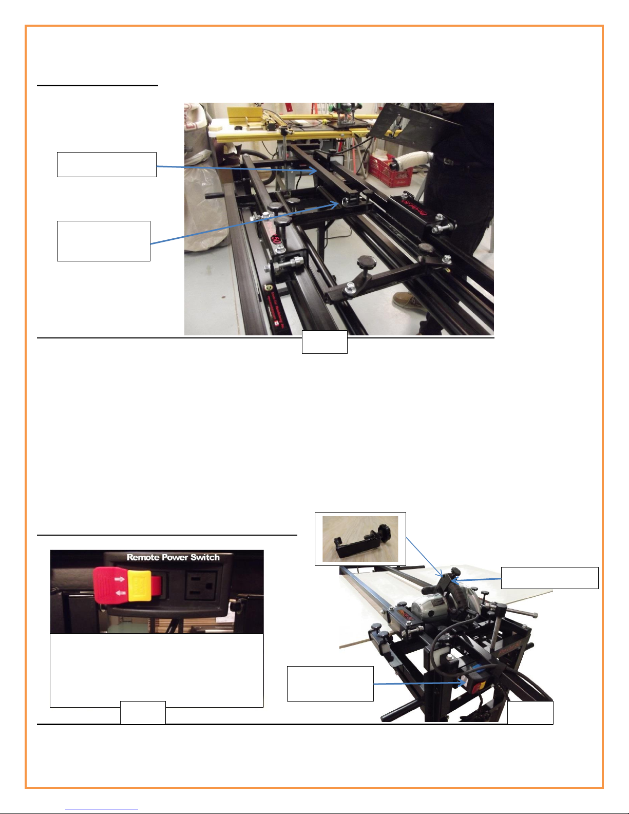
Sled Push Handle
To install the sled push handle, insert the push rail into the push rail bracket located on the sled, line up the
holes and install the quick release pin. For most operations you will probably leave the sled push rail installed
however for small routing projects it may be easier to remove the sled push rail.
Remote Power Switch and Saw Trigger Lock
Sled Push Handle
Push Rail quick
Release Pin
The power switch box is used to plug the
power tool into and comes equipped with
a power lock out.
Saw Trigger Lock
Fig 21
Fig 22
Fig 23
Remote Power
Switch

17
The Pro-Cut 50 is designed to allow the saw to operate without the necessity of holding the power switch of
the saw in the “on”position while cutting material. To accomplish this, a saw trigger lock and remote power
switch are included with the Pro-Cut 50.
Caution must be taken when installing the saw trigger lock.
Be sure the saw is unplugged from the power source when installing the saw trigger lock.
Carefully place the saw trigger lock over the saw trigger. It will be necessary to depress the safety lock on the
saw trigger lock while holding the saw trigger lock up against the saw trigger. Slowly tighten the screw knob on
the saw trigger lock being careful not to damage the saw trigger switch. Do not over tighten the saw trigger
lock as it could result in damage to the saw trigger switch.
Pro-Cut 50 Table Top Insert
Be sure to read the section on Cross-Cutting and Rip-Cutting BEFORE you make any cuts. The new version of
the Pro-Cut 50 and the Pro-Cut 50DC comes with a table top insert rather than 4 rollers as on the previous
version of the Pro-Cut 50. Although the rollers made it easy to run large 4’ x 8’ sheets through the Pro-Cut 50,
the draw back was that it required a table top for smaller panels (more so for routing). The new version Pro-
Cut 50 with the table top insert addresses this situation and, by design, still allows for large panels to run
through the Pro-Cut 50 with ease. The table top insert has been designed from standard 5/8” thick melamine
material available at most building supply stores and is easy to replace should it become necessary. The table
top insert that comes with the Pro-Cut 50 will last for years but since it is possible to accidently cut into the
table top in some cases (more so with the router) it is important the table top insert is made of a material
other than metal. We choose a standard material so the woodworker is able to make a replacement table top
with ease should it become necessary. Making a replacement table top will be explained in detail later in this
user guide.
If you own a previous version Pro-Cut 50 you may decide to remove the rollers and make a table top using the
same procedure as described below. Your table top will have a finished thickness of 1-1/2” so it sits flush to
the clamping rails of the Pro-Cut 50 frame.
Placing the Saw in the Pro-Cut 50 Sled
Be sure to read the sections on Cross-Cutting and Rip-Cutting BEFORE you make any cuts. These
IMPORTANT sections will explain the saw depth gauge and setting the saw blade height.
A premium grade saw is included with the Pro-Cut 50 system. If you decide to upgrade to the Pro-Cut 50DC
that includes dust collection, it includes a different saw with a dust collection port and the necessary hoses
and hose hanging system. Both systems have the included saw pre-mounted to the saw insert plate. Installing
or changing the saw position in the sled is fast and easy. The saw is installed in one direction for cross cutting
and another direction for rip cutting as shown below.

18
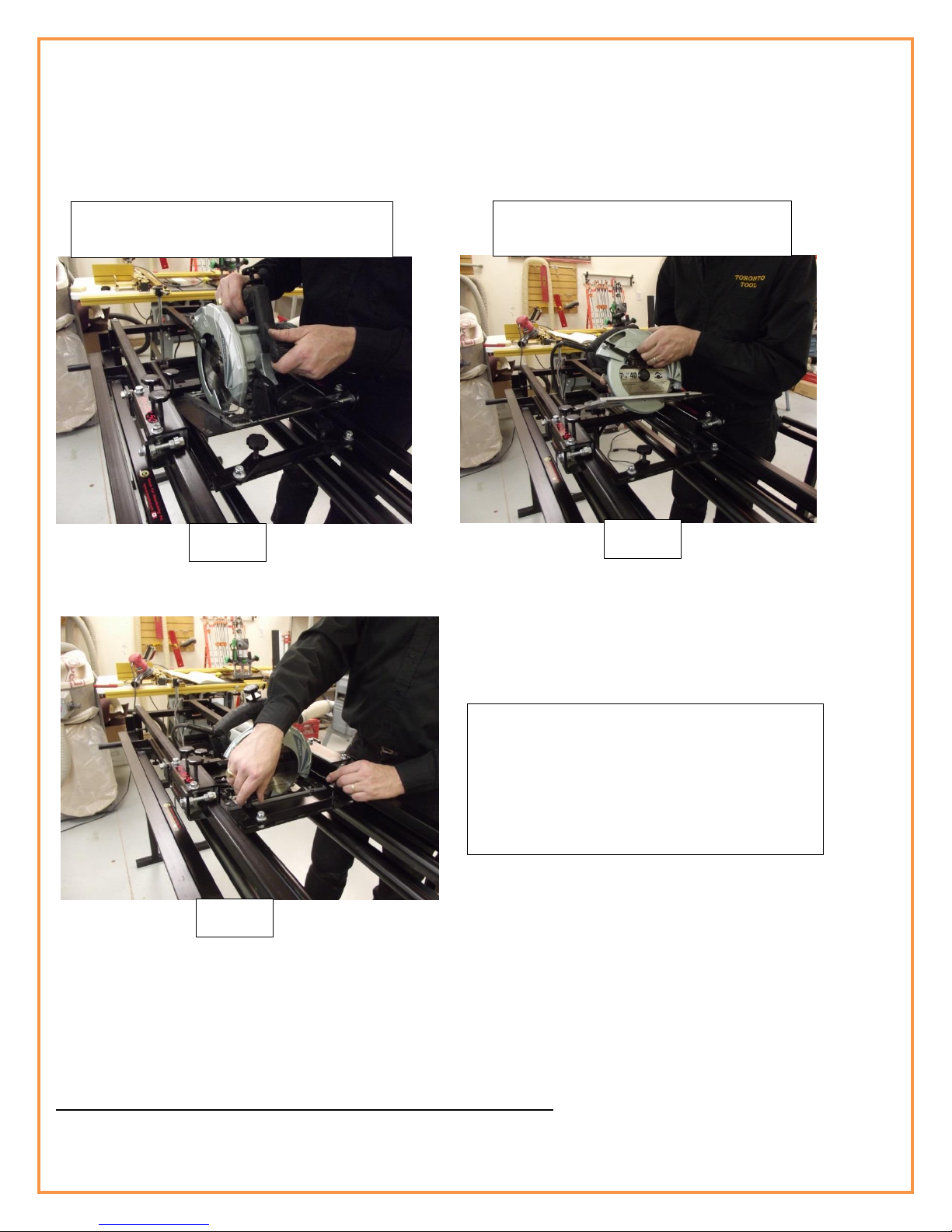
Installing the saw for cross cutting
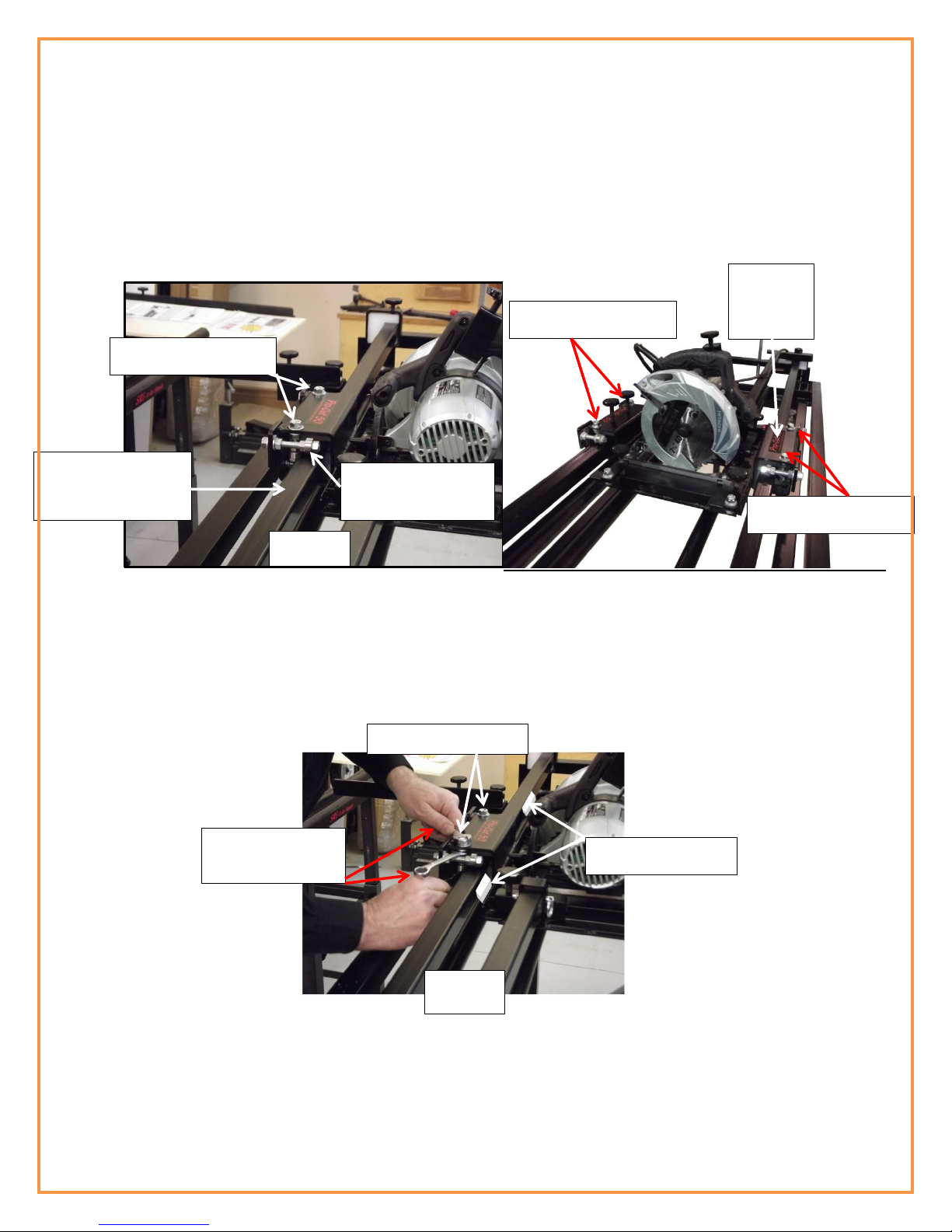
The saw insert is locked into the sled using (4) separate locks. There are 2 back lock screws and two front
swing arm lock screws.
1) To install the saw for cross cutting, position the saw as shown in Fig 24.
2) Slide the insert plate under the two back lock screws as shown in Fig 24, 25 and tighten the back lock
screws against the insert plate.
3) Swing the front insert lock arms over the saw insert plate and screw down the lock knob screws tightly
against the insert plate.
Fig 24
Fig 25
Fig 26
Slide insert plate
under the back
lock screws
Tighten both back
insert lock screws
Swing the front insert lock arms over the
insert plate and screw the lock knobs
tight against the insert plate
19
Installing the Saw Insert for Rip Cutting
The steps for installing the saw insert plate for rip cutting are exactly the same as for cross cutting except the
saw insert plate is turned 900.
Installing Your Plunge Router to the Router insert Plate
Included with the Pro-Cut 50 is a separate router insert plate. The router insert plate is exactly the same size
as the saw insert plate so interchanging the two requires no adjustment.
Fig 27
Fig 28
Fig 29
Loosen all 4 lock screws and remove the
saw insert from the sled
Turn the saw 900 and place the saw
insert back into the sled for rip cutting.
Slide the saw insert plate under the back screw
locks and screw the locks down tight against
the saw insert plate. Swing the screw lock
brackets over the saw insert plate and tighten
the screw locks against the saw insert plate.
Table of contents


