Stallion CWI-B1412 Manual instruction

Setup and Operation Manual
Stallion CWI-B1412
Features
• Gold Anodized Dovetail Ceramic Blade Guides
• Optional Dual Ball Bearing Blade Guides
• Deluxe Easy Glide Ball Bearing Fence
• Bright Light LED Viewing Strip
• Robust Cast Iron Table Trunnion Bracket
• Cast Iron 14” Wheels
• Quick Release Blade Tension
• Blade Tracking View Window
• One Piece Welded Steel Frame for Rigidity
• Dual Voltage Motor with Overload Protection
Specications
• Blade Length: 112”
• Blade Capacity: 1/8”–3/4”
• Blade Speed: 3250 FPM
• Table tilt range: –5° to 45°
• Table Size: 16” x 20”
• Floor to Table Height: 36.5”
• Throat: 13.5”
• Max Height of Cut: 12”
• Fence: Steel w/ anodized aluminum sides, T-style
• Dust port diameter: 4”
• Motor speed: 1725 RPM
• Floor Space: 33” x 30” x 72”
• Shipping weight: 253 lbs
• Motor (pre-wired 120V): 1.75 HP, 120/240V 14/7 A

Thank you for choosing this CWI Woodworking Technologies model B1412 14" Floor Model 1.5 HP Band-
saw. This saw has been carefully tested and inspected before shipment and if properly used and maintained,
will provide you with years of reliable service. For your safety, as well as to ensure optimum performance
please read this manual before assembling, installing and operating the unit.
This manual is not a substitute for formal woodworking instruction. If you are not sure about the safety of
performing a certain operation or procedure, do not proceed until you can conrm, from knowledgeable and
qualied sources, that it is safe to do so. Keep this manual for future reference.
CWI Woodworking Technologies
1608 St. James Street, Winnipeg, MB
Canada R3H 0L2
1-888-389-4752 Ext 101 • 1-204-783-6867
Five Year Limited Warranty:
All tools sold by CWI Woodworking Technologies used for hobby, or educational applications are warranted
for a period of 5 years (60 months) from the date of purchase. CWI Woodworking Technologies agrees to
repair or replace any part or component, which upon examination, proves to be defective in either workman-
ship or material to the original purchaser during this 5-year warranty period, subject to the “conditions and
exceptions” as listed below. This warranty may not be transferred.
To le a claim:
To le a claim under our Standard 5-year Limited Warranty all defective parts, components or machinery
must be returned freight or postage prepaid to CWI’s main warehouse or your closest CWI dealer for inspec-
tion and approval for replacement.
A copy of the original proof of purchase must be sent with the return of the product being claimed for war-
ranty. Include information clearly stating the model and serial number of the tool and an explanation of the
complaint or defect in material or workmanship.
Conditions and Exceptions:
This coverage is extended to the original purchaser only. This warranty does not apply to electrical com-
ponents, CNC machinery, defects due directly or indirectly to misuse, abuse, negligence, accidents, dam-
age in handling or transport, repairs, alterations, lack of maintenance or normal wear and tear. Under no
circumstances will CWI be liable for incidental or consequential damages resulting from defective products.
All other warranties, expressed or implied, whether of merchantability, tness for purpose, or otherwise are
expressly disclaimed by CWI. This warranty does not cover products used for commercial or industrial pur-
poses. This limited warranty does not apply to accessory items such as blades, drill bits, sanding discs or
belts and other related items. Repairs made without the written consent of CWI Woodworking Technologies
will void all warranty.
CNC machinery, electrical components or tools used for commercial or industrial or purposes are warranted
for a period of one year from date of original purchase.
Warranty Information

Table Of Contents
Warranty ...........................................................2
Safety Rules ...........................................................4
Electrical Requirements
Grounding Instructions ................................................5
Circuit Capacity ...........................................................5
Converting the Motor to 240V.......................................5
Extension Cords ...........................................................5
Introduction ............................................................6
Identication of Main Parts and Components .........6
Unpacking
List of Contents ..........................................................7
Additional Tools Required.............................................7
Bandsaw Assembly
Initial Cleaning ............................................................8
Mounting the Table .......................................................8
Installing the Table Insert..............................................9
Installing the Fence
Installing the Fence Brackets .......................................9
Installing the Fence Rails ...........................................10
Measuring Tape
Installing the Measuring Tape.....................................10
Installing the Blade
Installing a Bandsaw Blade ........................................11
Removing a Bandsaw Blade ......................................11
Blade Orientation........................................................12
Tensioning the Blade
Tension Scale .........................................................12
Turning Tension On/O...............................................12
Checking Tension .......................................................12
Adjusting Blade Tracking
Checking Tracking ......................................................13
Adjusting Blade Tracking............................................13
Table Stop Adjustment
Setting the Table Stop Bolt .........................................13
Setting the Table Tilt Pointer.......................................13
Squaring the Table
Squaring the Blade to the Miter Slot...........................14
Squaring the Fence
Squaring the Fence to the Miter Slot..........................14
Adjusting Fence Alignment.........................................14
Adjusting the Fence Height ........................................14
Guide Alignment
Guide Depth from Gullet.............................................15
Guide Distance from Blade.........................................15
Thrust Bearing Adjustment .........................................15
Dust Collector Connection
Collecting to a Dust Collector .....................................16
Ball Bearing Guides (optional accessory)
Guide Depth from Gullet.............................................16
Guide Distance from Blade.........................................16
Thrust Bearing Adjustment .........................................17
Basic Controls
On/O Switch .........................................................17
Starting the Saw .........................................................17
Stopping the Saw .......................................................17
Guard Height Adjustment ...........................................17
Table Tilt Adjustment...................................................18
Basic Operation
Rip Cutting ..........................................................18
Resawing ..........................................................18
Adjusting for Drift........................................................18
Measuring Drift ..........................................................19
Cross Cutting ..........................................................19
Bevel Cutting .........................................................19
Cutting Curves .........................................................19
Radius Chart ..........................................................19
Maintenance
Blades ..........................................................20
Guide Bearings .....................................................20
Wheel Tires ..........................................................20
Lower Wheel Brush ..............................................20
Motor Belt ..........................................................20
Parts List and Diagrams .................................... 21-25

To help ensure safe operation, take a moment to learn the machine’s applications and limitations, as well as po-
tential hazards. CWI Woodworking Technologies disclaims any real or implied warranty and holds itself harmless
for any injury that may result from improper use of its equipment.
Rules for Safe Operation
15. Use suitable support when cutting stock that does not
have a at surface. Always hold stock rmly against table.
16. Do not cut long stock without adequate outfeed sup-
port.
17. Avoid working from awkward or off balance positions.
Do not overreach while cutting, and keep both feet on the
oor.
18. Keep guards in place and in working order. If a guard
must be removed for maintenance or cleaning, be sure it is
properly reattached before using the saw again.
19. Never leave the machine running when not in use.
20. Use of parts and accessories NOT recommended by
CWI may result in equipment malfunction or risk of injury.
21. Never stand on machinery. Serious injury could result
if the tool is tipped over or if the blade is unintentionally
contacted.
22. Always disconnect tool from power before servicing or
changing accessories such as blades, or before perform-
ing any maintenance, cleaning or adjustments, or if the
machine will be left unattended.
23. Make sure that switch is in the OFF position before
plugging in the power cord.
24. Make sure the tool is properly grounded. If equipped
with a 3-prong plug it should be used with a three-pole
receptacle. Never remove the third prong.
25. Do not use this saw for other than its intended use. If
used for other purposes, CWI disclaims any real implied
warranty and holds itself harmless for any injury, which
may result from that use.
1. Do not operate the saw when tired, distracted, or under
the effects of drugs, alcohol or any medication that impairs
reexes or alertness.
2. The working area should be well lit, clean, and free of
debris.
3. Keep children and visitors at a safe distance when the
saw is in operation; do not permit them to operate the saw.
4. Childproof and tamper proof your shop and all machin-
ery with locks, master electrical switches and switch keys,
to prevent unauthorized or unsupervised use.
5. Give your work your undivided attention. Even a mo-
mentary distraction can lead to serious injury.
6. Fine particulate dust is a carcinogen that can be
hazardous to health. Work in a well-ventilated area and
whenever possible use a dust collector and wear eye, ear
and respiratory protection.
7. Do not wear loose clothing, gloves, bracelets, neck-
laces, or other jewelry while the saw is in operation.
8. Be sure that tools, scrap, drinks and other clutter are
removed from the table surface before operating.
9. Keep hands away from the blade and all moving parts.
Use a brush, not your hands, to clear away chips and dust.
10. Adjust and position upper and lower blade guides
before cutting. Upper guard should be 1/8” above material
to be cut.
11. Adjust blade tension and tracking before cutting.
12. Always use a clean, properly sharpened blade. Dirty
or dull blades are unsafe and can lead to accidents.
13. Ensure blade has reached full speed before cutting.
14. Bandsaw blade teeth must point down toward table.
4
BEFORE CONNECTING THIS SAW TO THE POWER SUPPLY, VERIFY THAT THE SUPPLY VOLTAGE MATCHES THAT OF
THE MOTOR. INCORRECT SUPPLY VOLTAGE CAN RESULT IN SERIOUS INJURY TO THE USER AND DAMAGE TO THE MA-
CHINE. IF YOU ARE UNSURE OF THE SUPPLY OR EQUIPMENT VOLTAGE, CONTACT A QUALIFIED ELECTRICIAN BEFORE
ATTEMPTING TO USE THE SAW. DO NOT EXPOSE THIS SAW TO RAIN OR USE IT IN WET OR DAMP LOCATIONS.
Electrical Requirements
If you are unsure about whether or not your receptacle
is grounded, check with a qualied electrician or service
person.
Circuit Capacity
Make sure that the circuit used to power your saw is
properly sized to handle the saw and any other equip-
ment that is powered by the circuit. If the circuit breaker
trips regularly, equipment connected to the circuit is
drawing more amperage than the breaker can handle.
Move some equipment to another circuit or have a
licensed electrician install a higher capacity circuit. If the
circuit is not overloaded and the breaker continues to
trip when the saw is used, there may be a fault with the
saw’s motor. Contact a licensed electrician or CWI.
Converting the Saw to 240V
The motor is pre-wired for use with a 120VAC power
supply. The saw can be converted for use with 240V
single phase, but it is recommended that a qualied
electrician perform this conversion. Follow the wiring
diagram below to change the motor to 240V. It is also
recommended to change the saw’s plug to a NEMA
6-15P type plug to prevent accidental usage on a 120V
circuit.
Minimum Wire Size of Extension Cord
Equipment
Current
Rating
(Amperes)
Length of extension cord (feet)
115V 25 50 100 150
230V 50 100 200 300
Wire size (AWG)
5 or less 18 16 16 14
6-10 18 16 14 12
10-12 16 16 14 12
12-16 14 12 Not recommended
C
B
A
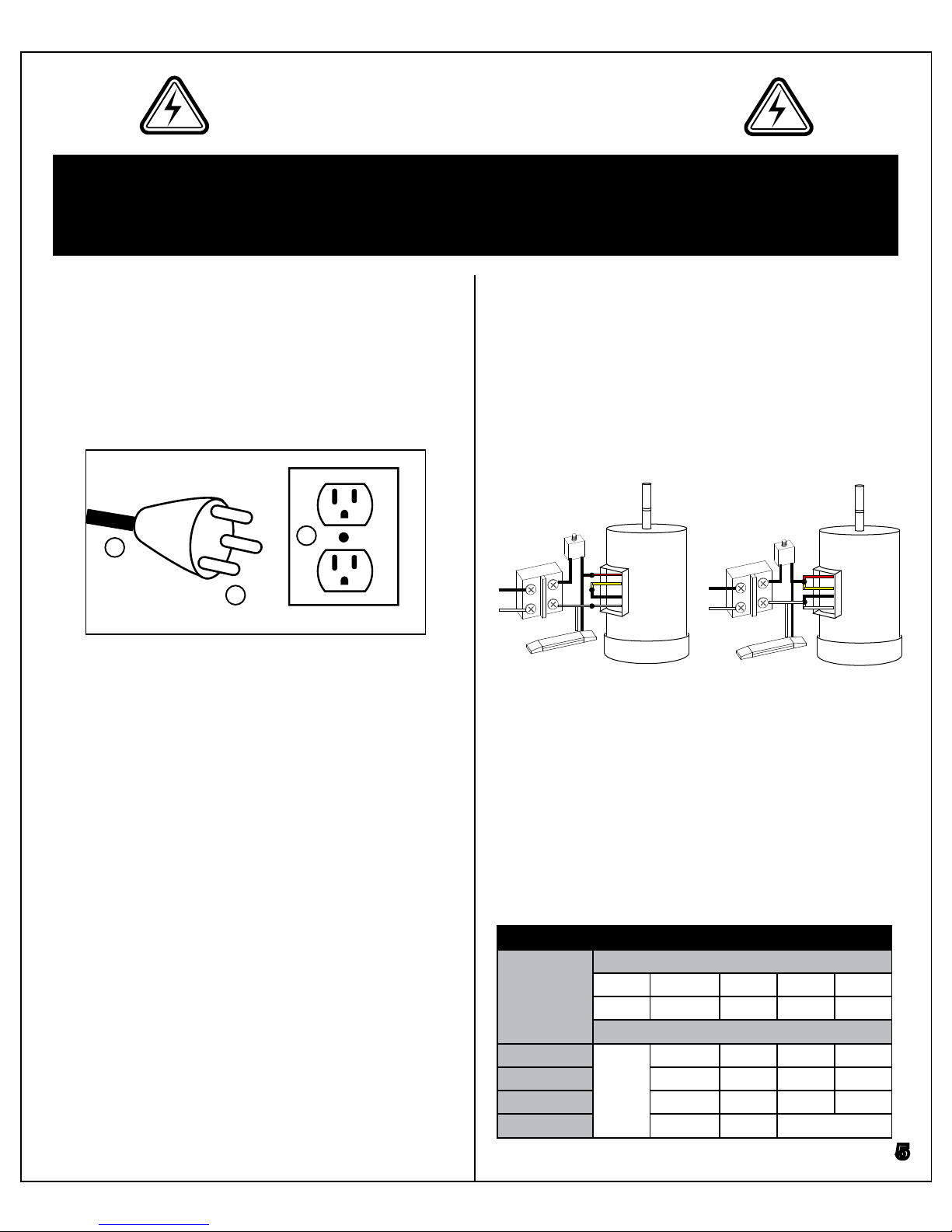
Grounding Instructions
In the event of an electrical malfunction or short circuit,
grounding reduces the risk of electric shock to the op-
erator. The motor of this machine is wired for 120V and
is equipped with a 3-conductor cord (A) and a 3-prong
grounded plug (B) to t a matching grounding type re-
ceptacle (C).
Extension Cords
If you need to use an extension cord to power the saw,
always use a 3-prong extension cord with grounding pin
and a matching 3-prong receptacle. Repair or replace
a damaged extension cord or plug immediately. Make
sure the cord rating is suitable for the amperage listed
on the motor ID plate. An undersized extension cord
will cause a drop in line voltage resulting in loss of saw
power and dangerous overheating of the extension
cord. The table below shows the recommended mini-
mum wire size for extension cord usage. The smaller
the number, the heavier the gauge.
5
240V
Motor
120V
Switch
Motor
To Plug
Overload
LED Strip
Switch
To Plug
Overload
LED Strip
6
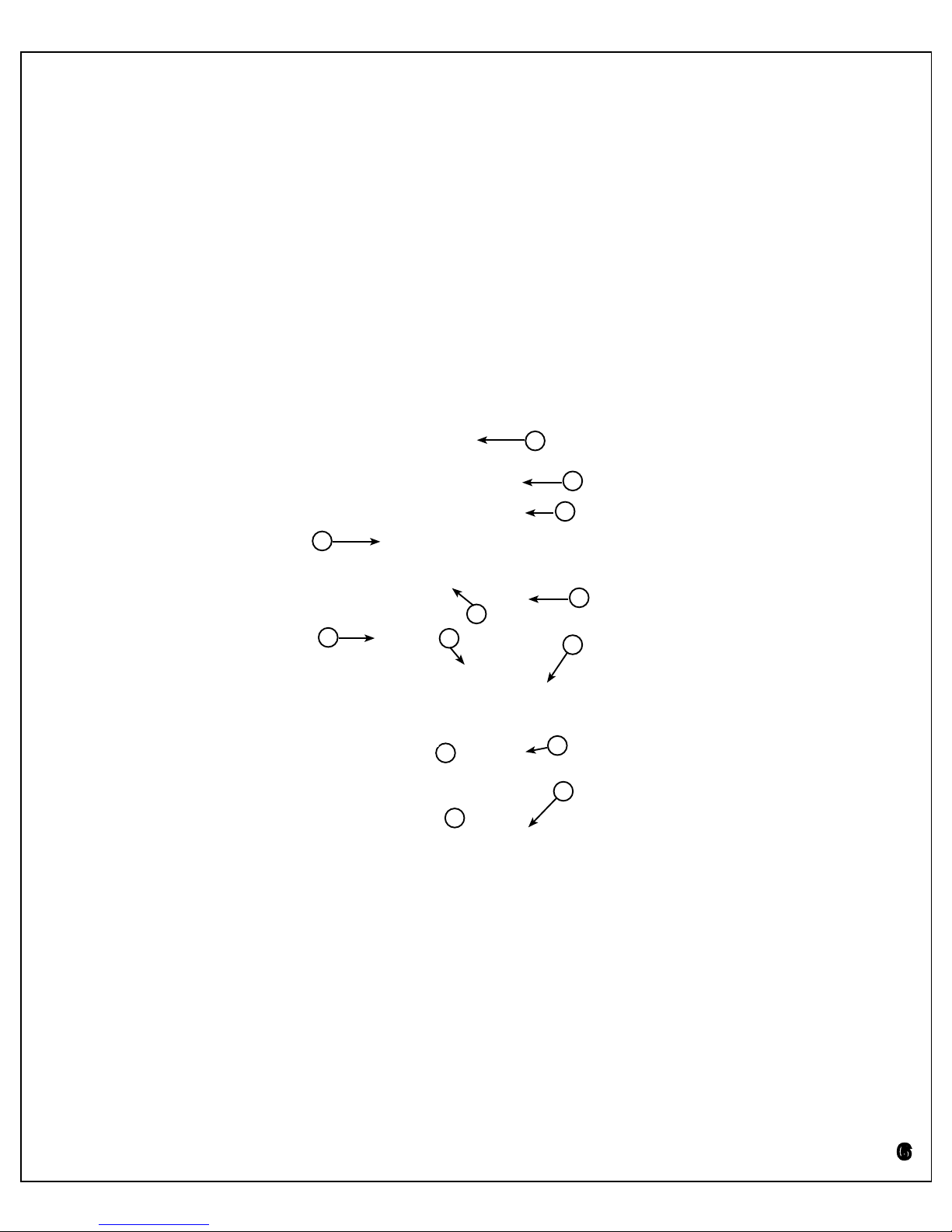
Identication of Main Parts and Components
A- 14” Woodworking Bandsaw
B- Work Table
C- Rip Fence
D- On/O Switch
E- Quick Release Blade Tension Lever
F- 4” Dust Inlet
G- Gold Anodized Dovetail Ceramic Blade Guides
H- Rip Fence Locking Handle
I- Blade Tracking View Window
J- Wheel Door Lock Knobs
K- LED Worklight
L- 1.75 HP Motor
A
B
C
D
E
F
G
I
J
K
H
This saw has been designed for cutting solid wood as well as manufactured wood materials such as plywood, wood
panelling, particleboard, MDF, and other wood based products. This saw is not designed for cutting metals or any
other non-wood product.
This saw is designed for use with bandsaw blades having a width from 1/8” to 3/4”, and a length of 112”. With the
ceramic blade guides raised to their highest position and the table set at 90º, the maximum resaw capacity is 12”. The
work table can be tilted 5° to the left, and 45° to the right.
Pay close attention to the saw’s balance when lifting it; the saw is very heavy and could topple causing injury or ma-
chine damage. Use a forklift to lift the saw and ensure another person helps guide the machine into place. Once set,
the saw can be levelled and mounted to the oor or machine mounts for safety and stability.
Introduction
J
L
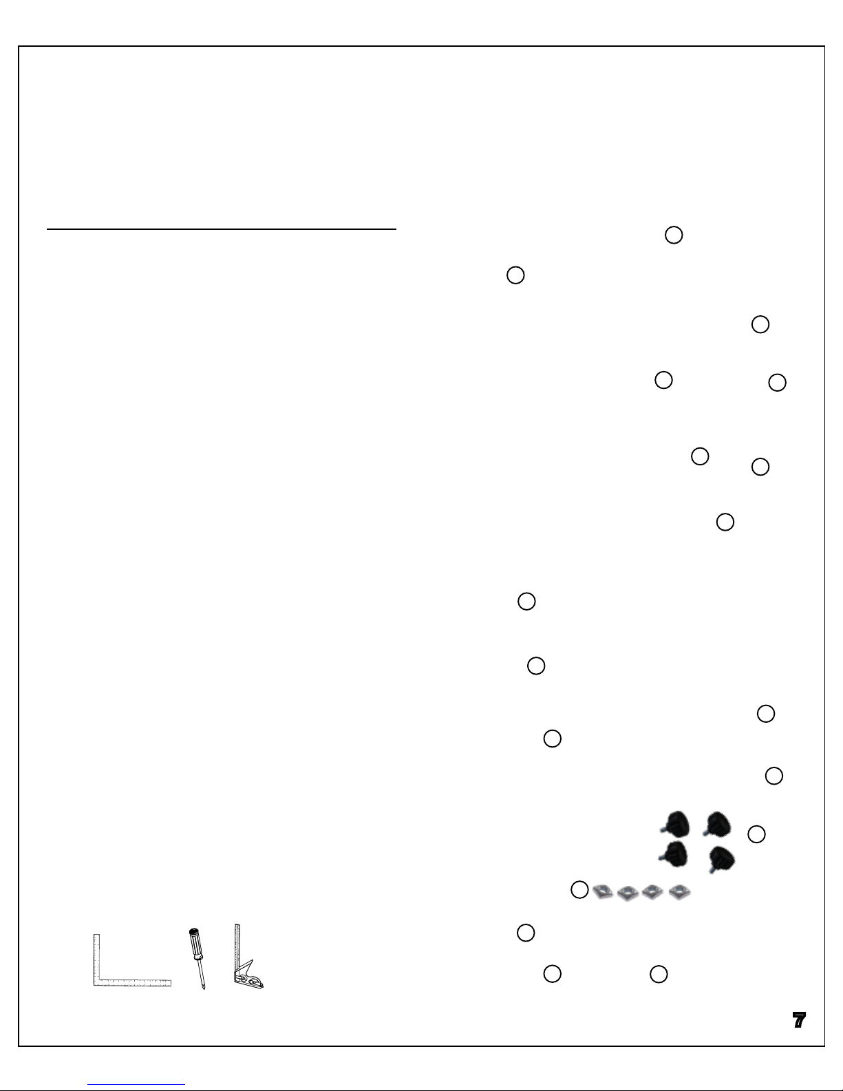
Carefully unpack and remove the saw and its components from the box and check for damaged or missing
items as per the list of contents below. Report any damaged or missing items to your CWI distributor imme-
diately.
List of Contents Quantity
A- Saw ......................................................1
B- Table ......................................................1
C- Threaded lock knob .........................................2
D- Table insert ......................................................1
E- Table pin ......................................................1
F- Stamped wrench ..............................................1
G- Allen key ......................................................2
H- Hex head bolt & at washer.............................4
I- Front rail tube ....................................................1
J- Rear rail tube....................................................1
K- Rip Fence ......................................................1
L- Large rail brackets............................................2
M- Small rail brackets...........................................2
N- Lock knob with post .........................................4
O- Square nut ......................................................4
P- Measuring tape ................................................1
*Q- Upper ball bearing guide................................1
*R- Lower ball bearing guide ................................1
*Optional Accessory
Additional Tools Required
In addition to the tools supplied with the saw, you will need the
following tools during assembly and setup:
• Phillips Head Screwdriver
• Machinist’s Square
• Straight Edge
• A Friend to Help Lift
Unpacking
^
j
h
A
D
B
E
J
N
H
K
O
7
C
F
M
G
I
QR
P
L

Initial Cleaning
The cast iron table is covered with a special protec-
tive coating to prevent rusting during shipping. Re-
move this coating using a rag and solvent (mineral
spirits or paint thinner). Most of the coating can be
carefully scraped o with a putty knife before solvent
cleaning. Take care not to scratch the table when
scraping.
Bandsaw Assembly
Do not apply solvent to painted metal or plastic sur-
faces as this could damage these surfaces. Once
the protective coating has been removed, a surface
protector such as paste wax should be applied to the
table for additional protection and to reduce friction
between the workpiece and table during operation.
Use a screwdriver and solvent soaked rag to clean
the coating out from the miter slots.
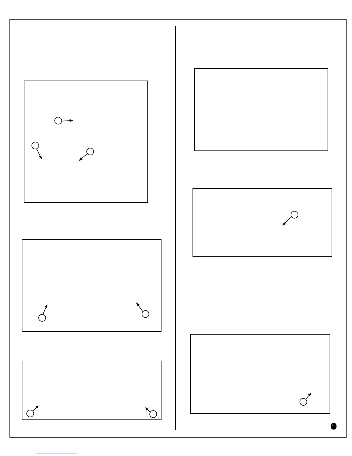
Mounting the Table
When the bandsaw table is installed, the trunnions on
the underside of the table (A) rest in the saw frame’s
trunnion supports (B), and the left side of the table rests
on the table tilt stop bolt (C).
8
A
A
C
B
B
To install the table, rst remove the table’s pin (D).
D
Attach the tilt support arm to the underside of the table
using two hex head bolts (J). Tilt the table to make ac-
cess easier. Once the support arm is attached, lower
the table and tighten the trunnion knobs.
9
If a blade is already installed, guide the table onto the
frame by rst sliding the blade (E) through the table’s
slot (F) until the blade is centered in the table’s insert
hole (G). Then rotate the table so that it is mounted as
shown below and rest it on the trunnion supports and tilt
stop bolt.
View from rear
E
F
G
While supporting the table, guide the trunnion bolts
through the mounting holes on the trunnion supports
(H).
HH
Thread the trunnion knobs onto the bolts, but do not
tighten (I).
II
J
Installing the Fence
Installing the Fence Brackets
Install the 2 large fence brackets on the front of the
saw table using hex head bolts and washers (A). Ori-
ent the brackets so that the recessed portion is paral-
lel with the oor (B).
B
AA
Installing the Table Insert
With the table mounted, the table insert can be pushed
into its mounting hole (K). The alignment tab lies on the
left side of the blade.
K

10
Installing the Fence Rails
Install the large fence rail on the front of the saw.
Slide a square nut into the fence’s slot (D), position
over the mounting bracket, and thread knob into the
square nut (E). Repeat with the second mounting
knob and square nut.
E
D
Install the small fence rail on the rear of the saw. Slide
a square nut into the fence’s slot (F), position over the
mounting bracket, and thread knob into the square
nut (G). Repeat with the second mounting knob and
square nut.
F
G
Slide both fence rails over so that they line up with left
hand side of the saw frame (H), and tighten the rail
knobs on either side (I) to secure the rails.
H
I
Place the fence on the rails (J) and ensure that it
slides left and right with ease. If the fence rests on
the table instead of the rails, loosen the rail bracket
mounting screws (K) and adjust the rails until the
fence clears the table.
J
K
Install the 2 small fence brackets on the rear of the
saw table using hex head bolts and washers (C). Ori-
ent the brackets so that the elongated mounting hole
attaches to the saw table.
C
Install the Measuring Tape
Remove its backing and stick the measuring tape
down in the front rail’s recessed slot (A).
A
Measuring Tape
Installing the Blade
Installing a Bandsaw Blade
Always unplug the saw and release the tension lever
before changing the blade on this bandsaw. Then,
remove the table insert (A) and table pin (B).
A
B
D
C
Unlock the cover latches (C), and open the upper and
lower wheel covers (D).
C
D
Slide the blade through the table slot (E), and slip it
between the guides (F).
Re-install the table pin and insert, tension the blade,
and adjust tracking as necessary. Every time a new
blade is installed, the guide assembly will require mi-
nor adjustment.
Removing a Bandsaw Blade
Blade removal follows the same process as instal-
lation, but in reverse. Always ensure that the saw is
unplugged and tension released before removing a
blade.
Slide the blade onto the upper (G) and lower wheels (H).
G
H
E
F
11

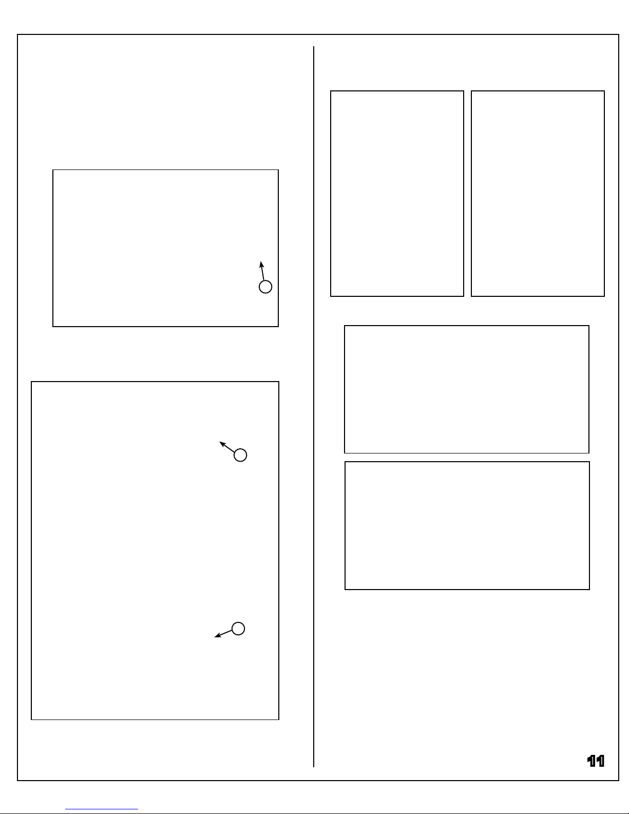
Blade orientation
Bandsaw blades must always be installed with the
teeth pointing downwards and towards the operator. If
the teeth cannot be rotated to face the correct direc-
tion, the saw blade may be inside out. Put on protec-
tive heavy gloves before turning a blade rightside out.
Tensioning the Blade
Tension Scale
Inside the top wheel cover, there is a tension scale
that indicates correct tension for various blade widths.
Line the red pointer up with the correct blade width on
the scale to set the blade to the proper tension.
To adjust the level of tension, turn the quick release
tension lever. Turning the lever clockwise will increase
tension, while turning it counter-clockwise will de-
crease tension. Do not engage the tension spring on
a blade without checking the tension scale rst. Over
tensioning a blade can cause damage.
Turning Tension On/O
The quick release lever is used for both setting tension
level, and turning tension on/o. Pull the handle down
to set tension on (A), and push it upwards to release
tension (B).
Tension Off
Tension On
A
B
Checking Tension
While the integrated tension scale will provide an
accurate reference for setting blade tension, dier-
ent blades may require extra adjustment. To conrm
adequate tension, unplug the saw and open the upper
wheel cover, then push against the saw blade near
the left hand frame slot (C). The blade should deect
about 1/4” with moderate pressure when properly
tensioned.
C
12

Checking Tracking
Ensure a blade is installed and properly tensioned,
and the saw is unplugged before adjusting the track-
ing. To reduce vibration and blade wear, the saw
blade’s gullet should track along the crown (the high-
est point) of the upper wheel (A).
Adjusting Blade Tracking
B
C
Make minor adjustments to the tracking knob while
rotating the upper wheel by hand (D). The blade’s
tracking position will shift as the wheel rotates, so pay
close attention to the blade’s position to avoid over ad-
justment. Once the blade is tracking correctly, tighten
the tracking knob’s jam nut to lock the blade in place.
Blade tracking should be checked every time a new
blade is installed.
A
Adjusting Blade Tracking
To adjust the blade’s tracking, rst loosen the tracking
knob’s jam nut (B), then turn the tracking knob (C) to
shift the blade’s position.
D
13
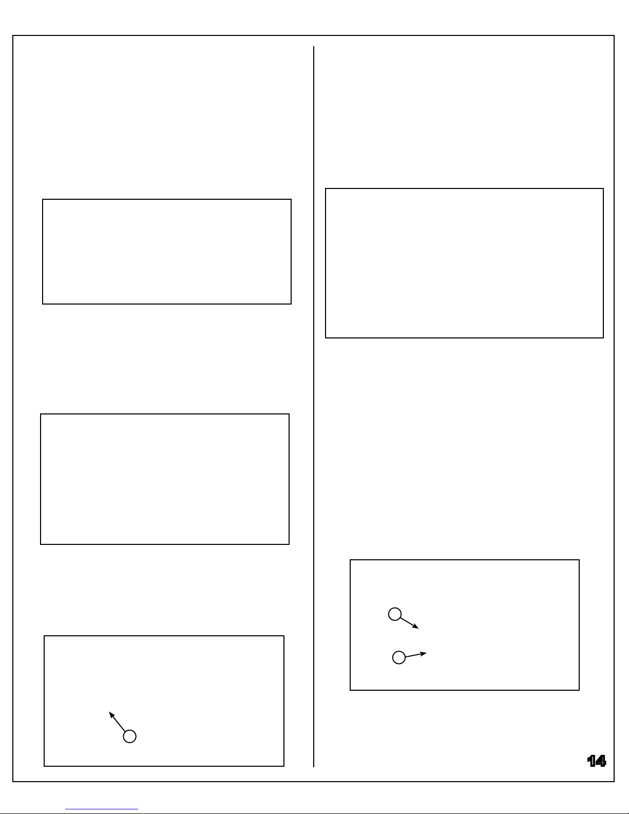
Table Stop Adjustment
Setting the Table Stop Bolt
The table stop bolt allows you to easily return the table
to 90° after tilting. To adjust the 90° stop bolt, rst make
sure the blade is correctly tensioned, and unplug the
saw. Then loosen the table trunnion knobs (A) and the
stop bolts locking hex nut (B).
B
A
A
Raise the upper blade guard assembly, and place a
square on the table against the blade (C). Adjust the
stop bolt to lower or raise the table until the table is
square to the blade. Re-tighten the stop bolt’s lock nut
to x the stop bolt in place.
C
Adjust the Table Tilt Pointer
With the blade tensioned and the table set square to
the blade, loosen the pointer screw (D) and set the
pointer to 0°. Re-tighten the pointer screw to secure
the pointer
D
14
Squaring the Table
Squaring the Blade to the Miter Slot
To ensure cutting accuracy, the miter slot must be
made parallel to the bandsaw blade. This alignment
is best performed with the largest blade size the saw
allows. To square the table, ensure the saw blade is
correctly tracking and unplug the saw. Then, loosen
the 6 trunnion bolts on the underside of the table (A).
Place an accurate straightedge along the blade (B).
The straightedge should lightly touch both the front
and back of the blade without touching the blade’s
teeth. Use a ne ruler to gauge the distance between
the straightedge and the miter slot. The distance
should be the same at both the front and back ends of
the miter slot (C&D).
A
A
A
A
B
C
D
If the distance between miter slot and straight edge at
both the front and back of the table is not the same,
adjust the table by lightly tapping it with a mallet (E)
until the distance between the blade and miter slot is
equal at both ends. Re-tighten the trunnion bolts to
lock the table in place.
E
Adjusting Fence Alignment
If the fence is not equidistant from the miter slot at
both ends, loosen the two bolts on top of the fence
(B), and adjust the fence’s alignment by lightly tapping
the opposite end of the fence (C) until it is parallel to
the mitre slot. Re-tighten the fence bolts and double
check the alignment at both ends of the fence.
Squaring the Fence
Squaring the Fence to the Miter Slot
The fence should be aligned parallel to the table’s miter
slot. Ensure that the miter slot is parallel to the blade,
then mount the fence close to the edge of the miter
slot and lock it in place. Measure the distance between
fence and miter slot at both ends of the table (A).
A
A
Adjusting the Fence Height
The fence should ride smoothly across the rails with-
out touching the table. Ensure the fence clears the
table, then using a combination square, measure the
distance between rail bracket and table top (D). If the
distance is not the same on either end of the table,
loosen the hex nut (E) and adjust the rail’s height.
B
C
D
E
Perform the same measurements and adjustment on
the rear of the saw to ensure the fence sits above the
table equally across its entire surface.
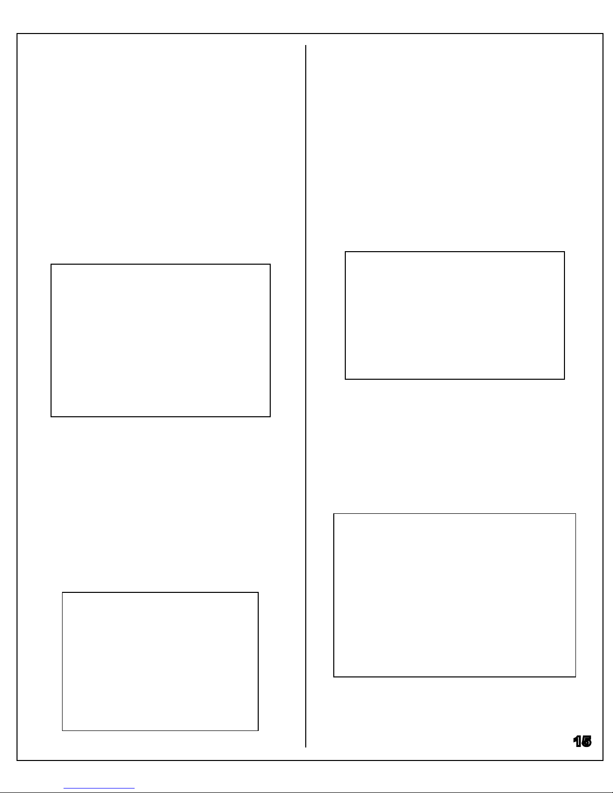
These same adjustments need to also be made at the
lower blade guide assembly underneath the table. Fol-
low the previous instructions to adjust the lower guides
(G) and thrust bearing (H).
H
G
15
Guide Alignment
The saw comes with ceramic blade guides installed;
these must be adjusted for optimal performance of the
saw. Ensure the blade is properly installed and ten-
sioned and the saw unplugged before making these
adjustments.
A
Guide Depth from Gullet
The front edge of the ceramic guides should be set
1/16” behind the blade’s gullet. To adjust this distance,
loosen the allen screw (A) and slide the guide assem-
bly backwards or forwards as required (B). Retighten
the allen screw once depth is set.
B
Rotate the wheels by hand to ensure 1/16” clearance
is maintained along the entire blade, and re-adjust if
necessary.
Rotate the wheels by hand to ensure guide position
is maintained along the entire blade, and re-adjust if
necessary.
E
F
Thrust Bearing Adjustment
The thrust bearing should sit just behind the blade
when it is spinning freely. During cutting, however, the
blade is forced backwards into the thrust bearing for
support.
Set the thrust bearing 1/16” behind the blade by loos-
ening the allen screw (E) and sliding the bearing back-
wards or forwards as required (F).
Rotate the wheels by hand to ensure 1/16” clearance
is maintained along the entire blade, and re-adjust if
necessary.
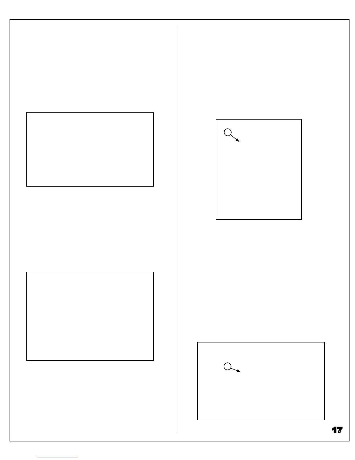
Guide Distance from Blade
Position the guides so that they are nearly in contact
with the blade but not touching. Their purpose is to
prevent the saw blade from wandering during cutting.
Set the distance between blade and guide to about
the thickness of a business card by loosening the allen
screws (C) and sliding the guides along their dovetail
mounts (D).
DD
CC
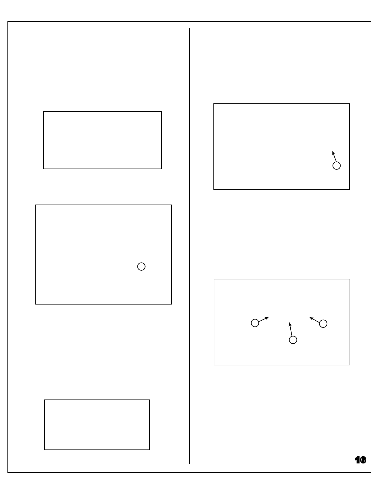
Connecting to a Dust Collector
It is essential to always use a proper dust collection
system when operating the saw. There is a 4" dust
outlet located on the rear of the saw for connection to a
dust collector (A).
A
Dust Collector Connection
To clean out dust trapped inside the saw cabinet, open
the wheel cover doors and vacuum out the inside of the
cabinet (B).
B
Ball Bearing Guides
For simplied guide setup,optional ball bearing guides
can be purchased from your CWI distributor. The bear-
ing guides install on the same dovetail mount as the
included ceramic guides, but are less prone to dam-
age from improper setup.
Guide Depth from Gullet
Like the ceramic guides, the front edge of the roller
guides should be set 1/16” behind the blade’s gullet.
To adjust this distance, loosen the allen screw (A) and
slide the guide assembly backwards or forwards as
required (B). Retighten the allen screw once depth is
set.
Rotate the wheels by hand to ensure 1/16” clearance
is maintained along the entire blade, and re-adjust if
necessary.
Guide Distance from Blade
The guides should just touch the blade when the saw
is o (C). During operation, the roller bearings should
spin along with the blade to help guide it during cut-
ting. Position the guides by loosening the allen screws
(D) and sliding the guides along their dovetail mounts.
Rotate the wheels by hand to ensure the guides just
touch the blade throughout its entire length, and re-
adjust if necessary.
D
D
C
16
AB
E
F
Rotate the wheels by hand to ensure 1/16” clearance
is maintained along the entire blade, and re-adjust if
necessary.
These same adjustments must be made to the lower
ball bearing guides as well. Note that the lower guide
with an angled corner mounts to the right of the blade
to allow the work table to tilt without hitting the guides
(G).
G
Starting the Saw
Ensure the yellow lockout tab is installed, and pull the
red start switch outwards. Wait for the saw blade to
reach full speed before cutting.
Stopping the Saw
Push on the red stop button and wait for the blade to
come to a complete stop.
Basic Controls
On/O Switch
This bandsaw has a large safety on/o switch with inte-
grated lockout tab. Start the saw by pulling outwards on
the switch (A). To stop the saw, push the button in. The
yellow tab (B) can be removed to lockout the saw; the
switch cannot be used to turn the saw on when the tab
is removed.
B
A
Guard Height Adjustment
The blade guard can be adjusted up and down to ac-
commodate dierent thicknesses of wood. The guard
should be set 1/8”–1/4” higher than the workpiece to
limit blade exing and slippage during cutting (C).
C
17
Thrust Bearing Adjustment
The thrust bearing should sit just behind the blade
when it is spinning freely. During cutting, however, the
blade is forced backwards into the thrust bearing for
support.
Set the thrust bearing 1/16” behind the blade by loos-
ening the allen screw (E) and sliding the bearing back-
wards or forwards as required (F).
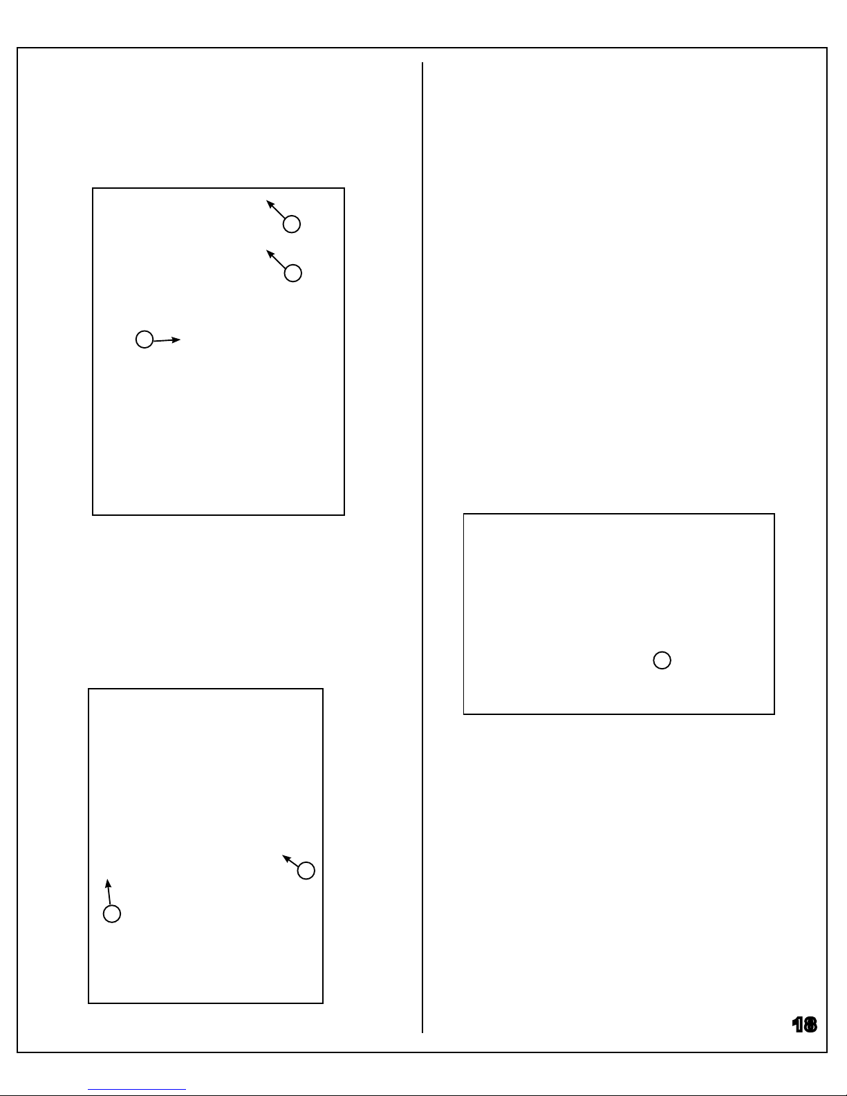
To adjust the guard’s height, loosen the lock knob (D).
The, turn the handwheel (E) clockwise to raise or coun-
terclockwise to lower the blade guard. Once the guard
is set correctly, retighten the lock knob. A scale on the
guard indicates its current setting (F).
Table Tilt Adjustment
Loosen the two table trunnion knobs on the under-
side of the table (G), and the tilt support knob (H),
then tilt the table to the desired angle. With the angle
set as, re-tighten the trunnion knobs.
The scale underneath the table will indicate the
table’s angle setting from- 5° to 45°.
18
H
G
D
E
F
G
• Ensure the blade is correctly installed and tensioned.
• Set the guard no more than 1/4” above the workpiece.
• Ensure the fence is locked and aligned for rip cuts.
• Wear safety glasses whenever the saw is in use.
• Use a blade appropriate for the type of cut being
made.
• Use a pushstick to guide material close to the blade.
• Never attempt to cut wood that is not supported by the
table, including round logs.
• When using the rip fence, ensure it is locked in place
before starting a cut.
• Let the blade come up to speed before starting a cut.
• If the workpiece is larger than the table, ensure it is
adequately supported and you have space to work.
Basic Operation
Rip Cutting
Cutting a workpiece lengthwise to reduce its width is
called ripping. To perform a rip cut, hold the workpiece
with both hands and push it into the blade while keep-
ing the side rmly against the rip fence so that it is cut
straight (A).
A
Resawing
A special type of rip cutting than is performed on a
bandsaw is called resawing. This process can be used
to cut thin veneer pieces out of a larger workpiece to
reduce waste and produce bookmatched panels. To
achieve the best results, a special resawing blade is
typically used with a tall add-on fence for resawing.
Adjusting for Drift
Drift while resawing or ripping wood is an issue com-
mon to all bandsaws; the amount of drift varies with
wood species, blade type and condition. To eliminate
drift and provide a straight cut, adjust the fence’s angle
from the blade by following the procedure on page 14.
Instead of squaring the fence, angle it to support the
workpiece and provide a straight cut even though it is
at an angle from the blade.

19
B
Cross Cutting
Cutting against the grain to shorten the length of a
board is called cross cutting. For better control during
cross cutting, use a miter gauge (B). A miter gauge
may be used in either table slot.
Bevel Cutting
Both rip and cross cuts can be made with the table
set at an angle to provide a bevel cut (C). Ensure that
the workpiece is adequately supported when making
bevel cuts.
To set the table angle, loosen the trunnion knobs
and the tilt support knob, and tilt the table as desired.
Tighten all 3 knobs and re-check the table’s angle.
B
Cutting Curves
A bandsaw is especially useful in cutting curves.
This type of cut is usually made without a fence or
guide (B). Carefully turn the stock to ensure the blade
doesn’t twist while following your cut. If the curve is
too sharp and forces you to repeatedly cut new kerfs
in the stock, use a narrower blade that can accommo-
date a tighter radius.
When pulling a workpiece backwards to change a cut,
don’t withdraw the workpiece from the blade entirely.
Instead, turn the workpiece and cut through a waste
area. When cutting long curved sections, make relief
cuts as you go to prevent blade binding and twisting
When cutting circles, it is important to note that the
saw blade’s width dictates the minimum possible
radius of cut. Creating a tight curve requires a smaller
blade than a large curve. The radius chart below
shows typical saw blade widths and their correspond-
ing minimum radius. Note that this chart shows the
minimum radius only; larger radius cuts are possible.
3/4”
5/8”
1/2”
3/8”
1/4”
3/16”
1/8”
3/16”5/16”5/8”1-1/2”2-1/2”4”5-1/2”
Blade Width
Min. Radius
Radius Chart
C
Measuring Drift
Perform a test cut to determine how much drift is oc-
curing, then set the fence’s angle to match the test cut
angle. The saw will cut straight, but the fence will no
longer be parallel to the blade or miter slot.

• Inspect the on/o switch before each use. If it’s dam-
aged, replace the switch immediately.
• Inspect the saw blade for damage or chipped teeth
before each use. Never operate the saw with a dam-
aged blade.
• Keep the saw table clean and free of dust, pitch or
glue. A light coating of paste wax should be periodi-
cally applied to the table to help protect it.
• Occasionally open the cabinet doors and brush o
and vacuum out accumulated dust from inside the
cabinet and on the wheels.
• Periodically inspect the power cord for damage. To
minimize the risk of electric shock or re, never oper-
ate the saw with a damaged power cord.
• To minimize airborne dust particles, periodically
inspect all dust collection ttings and re-tighten as
needed.
Maintenance
20
Blades
Replace the bandsaw blade whenever it is worn out.
Typical symptoms of a worn blade are that it’s unable
to follow a line like it used to, or the cutting speed is
noticeably reduced.
Guide Bearings
Check the thrust bearings and optional roller bearing
guides whenever a blade is replaced. If the bearings
do not spin freely, they should be replaced.
Wheel Tires
Wheel tires should be replaced when they become
worn out or damaged. The saw blade will no longer
track straight when the tires are worn.
Lower Wheel Brush
The lower wheel brush keeps the lower wheel free of
dust and debris. Regularly check that the brush is in
good condition and in contact with the lower wheel. If
the brush becomes damaged or worn, replace it.
Motor Belt
Inspect the motor drive belt regularly; if it becomes
damaged or worn, replace it immediately. Unplug the
saw before changing this belt.
Notes
Table of contents
Other Stallion Saw manuals


