6HomewerksWW.com
ESPECIFICACIONES DEL PRODUCTO
ESPECIFICACIONES ESPECIFICACIONES
Max. Caudal: 1,2 GPM (4.54 LPM) a 60 PSI Cartucho de cerámica
ASME A112.18.1/CSA B125 Fabricado a incluir no más de 0,25% de contenido de plomo promedio pon-
derado en superficies mojadas
NSF 61-9
Cromo pulido, níquel cepillado o negro mate acabado Peso total: 3.42 lbs.
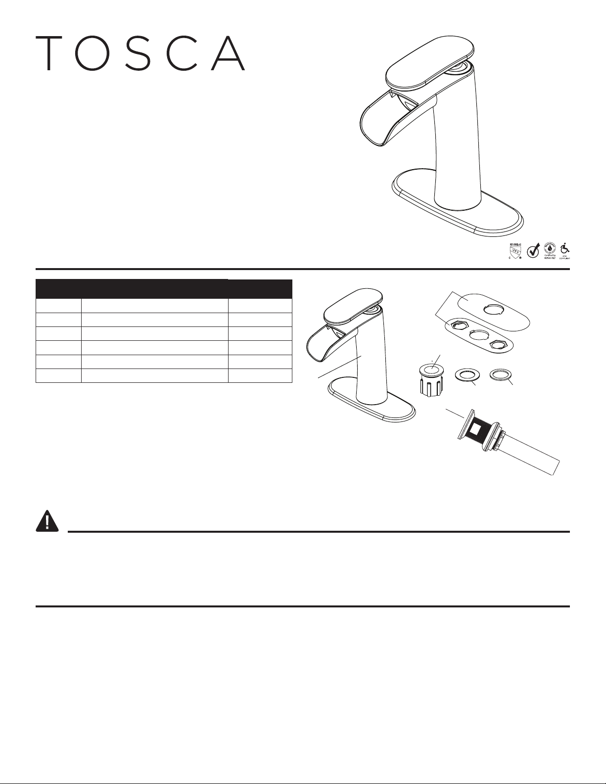
INSTRUCCIONES DE MONTAJE
1. Cierre la llave de paso debajo
del lavabo o la llave principa de
provisión de agua. Desconecte
los tubos de suministro de agua y
retire el grifo viejo.
Limpie y seque la superficie donde
se montará el grifo nuevo.
15. Para instalar el drenaje con tapón a
presión (F), gire el cuerpo de
drenaje (5.1) en sentido horario
para separarlo de la brida (5.2).
Retire de la brida (5.2) la tuerca de
montaje (5.3), la arandela plana
(5.4) y la arandela cónica de
caucho (5.5). Deje la junta de
caucho (5.6) en su lugar contra la
parte inferior del tapón a presión y
el anillo embellecedor (5.7).
5.2
5.3
5.4
5.5
5.7
5.6
5.1
Drenaje con tapón a presión (F)
5
2.
Antes de la instalación, desenrosque
la tuerca de montaje (C) y retire la
arandela metálica (D) y la arandela de
caucho (E).
NOTA: Los lavabos de un solo
orificio no requieren la placa de
cubierta y la junta opcionales (B).
C
D
E
26. Desde la parte superior del
lavabo, empuje la brida premon-
tada (6.1) con la junta de caucho
(6.2) a través de la abertura de
drenaje (6.3) en el lavabo.
6.
6.2 1
6.3
6
3. Inserte el cuerpo del grifo (A) a
través del orificio de montaje en el
lavabo (3.1). Desde debajo del lavabo,
deslice la arandela de caucho (E) y la
arandela metálica (D) sobre el
vástago metálico (3.2) en el cuerpo
del grifo (A).Asegure el cuerpo del
grifo (A) al lavabo enroscando la
tuerca de montaje (C) en el vástago
(3.2). Apriete a mano la tuerca de
montaje (C) en el vástago (3.2) hasta
que quede firmemente en su lugar
contra la parte inferior del lavabo.
NO APRIETE DEMASIADO.
E
CD
3.2
3.1
37. Desde debajo del lavabo,deslice la
arandela cónica de caucho sobre la
brida (7.1) con el extremo angosto
hacia arriba, hacia la abertura de
drenaje del lavabo. Deslice sobre la
arandela plana.Asegure la brida
(7.1) al lavabo girando la tuerca de
montaje (7.2) en el sentido horario
sobre la brida (7.1) hasta que quede
firmemente en su lugar contra el
fondo del lavabo.Vuelva a ensamblar
el drenaje con tapón a presión (F)
girando el cuerpo de drenaje (7.3)
en sentido horario hasta que quede
firmemente sujeto a la parte
inferior de la brida (7.1). NO
APRIETE DEMASIADO.
7.1
7.2 7.3
7
4.
Instalación de la placa de cubierta
opcional:
Alinee el orificio central en la placa
de cubierta y la junta (B) con el
orificio de montaje central (4.
1
) en el
lavabo. Inserte el cuerpo del grifo (A)
a través del orificio en la placa de
cubierta y la junta (B) y el orificio en
el freglavaboadero.Desde debajo del
lavabo, deslice la arandela de caucho
(E) y la arandela metálica (D) sobre el
vástago metálico (4.2) en el cuerpo
del grifo (A).Asegure el cuerpo del
grifo (A) al lavabo enroscando la
tuerca de montaje (C) en el vástago
metálico (4.2).Apriete a mano la
tuerca de montaje (C) en el vástago
(4.2) hasta que quede firmemente en
su lugar contra la parte inferior del
lavabo. NO APRIETE DEMASIADO.
A
CCDD
E
4.2
4.1
B
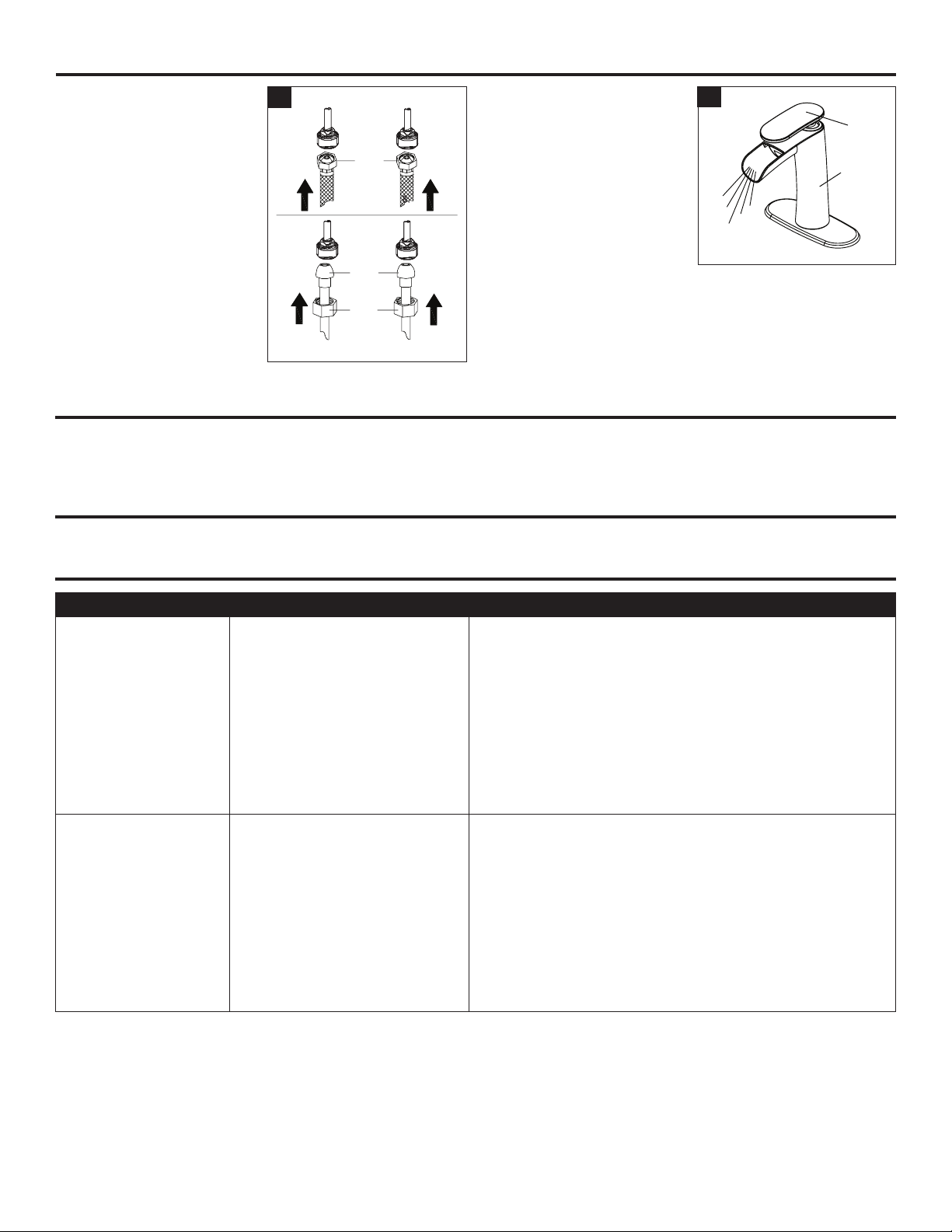
48. Para conectar los tubos de
suministro de agua, use salidas de
agua de 1/2 pulg. I.P.S. par grifo (8.1)
o tuercas de acoplamiento (8.2)
con punta de bola de diámetro
exterior de 3/8 pulg. (8.3). Estas
partes no están incluidas. Conecte
un extremo de cada una de los
tubos de suministro de agua a las
llaves de paso de agua fría y
caliente y apriete con una llave de
tubo. Coloque cada uno de los
otros extremos de los tubos de
suministro de agua en un balde.
Abra las dos llaves de de paso.
Deje correr el agua fría y caliente
sin interrupción durante unos 30
segundos para eliminar cualquier
residuo en los tubos. Cierre el
suministro de agua.
8.
8.1
8.2
8.3
8