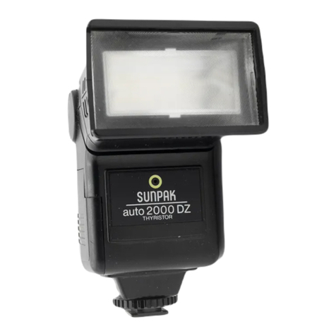
Toshiba Photo Products Co., Ltd. 414 User manual

TctSiHIEIA ELECTFICINIC FLASH TJNIT
rcrsiHrErA 4,4
r r\rsiTFlucTlctlu
*

f
SPECIFICATIC'NB
Guide number: 33 (ASA25 - fuet)
20 (DlN21' nteter)
Power Source: Two All€line mngalEP
Penlight batteries
AC 110'120V' or 2$'24O\l
Recycling time: With alkaline manganese batteries
Approx. 11 sec.
. AC oPeration. APPror ll seb.
Number of Flashes: With Alkaline manganese batteries
Approx. 150 flashes
Light distribution: 60' Vertical
50' Horizontal
Color temperature: Equivalent to daytime $nlight
Flash duration: ' l/1,000 sec.
Dimensions: 38X75x 101mm
NAME clF PAFITS
@ Battery compartment lid
@ Exposure guide table
@ AC socket
@ ICOC mode selector $rvitch
@ eC vottage selector sM,itch
@ AC voltage selector lock screw
O Neon lamp
@ Synch.o cord socket
@ Open flash button
@ Shoe
O) Direct contact(hot) shoe
@ Synchro cord
Weight l50g (w/o batt.) @ AC cord

-T
I
IF*
@
W*^
I -oe
(D
r
I
I
f,

EIEFCIFIE FLASHnIG
1. Inserting the BaCtcFa€.
(l) ptacing cells in the compartment:
Slide the lid as shown by an arrow.
(2) lnsert two alkaline manganese batteries as $rcst in the diagram and dide back the
a. Clperating on the ElC Cells
(1) Set the power selector switch to DC poEtion Then battery currert b oft
(2) Oscilating sound will be heard from the flash urit as charge go€s olr trhen
full charge is achieved, a neon lamp will be started to glow, and it b ready
to flash.
(S) white the flash unit is not used, turn the *itch to AC pocation to prevent
unnecessary consumption of batteries
a3. Ctperating on che Ae(Housahold wlaire)
(t) Set tne power selector s,vitch to AC position. Connect the AC cord with the
house current outlet. (AC socket does not acc@t the Plug if the *vitch is
located at DC position.)
(2) No oscilating sound can be heard but when the neon lamp sarts glowing,
the flash unit is ready to ffash.
(3) This unit is adjustable to 110-120V and 22G24OY.
Be sure to set the voltage adjuster to that of the place where you $toot.
Unscrew look voltage screw located left side of rcltage selector sritch.
tid -t
I
v

4. Gtpen flsh (Circuit test)
Pres the Open Flash Button after the Neon lamp has bcgun glowing
,t. Mounting on .the carrrera
This flash unit has a direct contact (hot) shoe Just insert Jre Unit shoe into the acce$or) dloe'
2. S\Aritching synchro terrt.rinal dt the shoe'
This unit isinstalled a teature of the ASM (Automaticsnoe Mount) System' provided with a direci
contact point in the shoe ' To use it on a camera which has no contact point in the shoe' ue the
synchronization cord'
oon a camera with a direct contact shoe'
(When it has a contact point in the shoe )
(1) Just insert the flash bracket into the shoe
(2) No synchroniTation cord is necessary'
oOn a camera which has no contact point'
(1) lnsert the synchronization cold into the socket'
(2) Mount the flash on the camera and connect the otlrer end of the cord to the synchronization
terminal of the camera'

3. Synchronizaticl r rich ciarEFa
Be sure to use the "X" contact point fo1,Eladr slnchrorization' Other contact points'
M and FP, do not synchronize with camerb.
(1) Almost all cameras with thedirect contact $loe are of "X" contact point system'
(Make sure by the manual that comes with your carrera')
(2) When a camera has two contact points, use "X" xrint
(3) Wittr a camera built in a synchronization selector' use the "X" point
(a) When a camera has only one contact point' it is of the "X" pdnt qderr in most
cases (Make sure by the manual that comes with the camera') ..l
I
,t
?i.ii:
3'.'J t >- .
,i.4,ia:
'?Er;
FC'EI FLASiHINGi
1. Setting Sihutter SPeed
(1) Between lens shutter cameras" " The unit synchronizes with all speeds
(2) The cameras with focal.plane shutter.... 'The unit will be synchronized when it is set
on the '.X,, mark or if the shutter speed is those shown in red figures Synchroni-
ing +""0 differs by depending on cameras, so make sure of it by the instruction
of respective camera.

2. Eleterrnination of the Correct Ex
To determine the correct exposure, please refer to the Exposure
given guide number. The guide number is the figure which
find by a Smple calculation the correct F:stop.
ODetermining the F:stop by Guide Number
Guide Number diMded by Distance:Correct F:stop
The guide number of this "TOSHIBA414" is 33in feet at ASA 25.
33(G.N.)+ 8 (Distance in feet):F: 4
This means, when you are using ASA25 film and taking a photo
the object, the correct F:stop will be F:4.
OHow to use the Exposure Guide Table
On the side of the flash unit, you will find the Exposure Guide Table. On the
upper part of the table are shown {ilm speed (ASA and DIN), and the left hand
si-de of the table are given various figures of distances (METER and FEET).
lf you refer to the F stop by aligning the film speed and the distance from subject, the given F stop.-sh'bws the correct
exposure. For example, if you use ASA25 film, and distance is 8 feet, the given F stop on the table will be F 4, and
this is the correct exposure.
GAUTIctN
(1) A high voltage and large power capacitor is built in the unit. In case of disorder, do not attempt to repair by an
unqualified hand.
(Z) t<eep the flash unit out of moisture, rain and water.
(a) Wnen the unit is not used for a long period of time, the capacitor becomes void of power, and will ta(e time to
become charged at first.
(4) lf it is not used for a long interval of time, charge it on the house current once a month. lt keeps the capacitor
in the best condition.
(S) take the dry cells out of the compartment if the unit is not used for a long time.
(6) Reptace all of the cells with fresh ones and use for the best result.
8 feet away from
\.
c\-.r;L
l*

\'-'
\]il
,f. I
I
\
I
''' '^'!i ' ToSHIETA pHcrro pFroE rJcrsr cct.r LTEI.
I No. 9.15, l.cHoME, AKASAKA, MTNATo-KU, ToKyo, JApAN
SK S I75OOG52JA2O OPRINTED IN JAPAN
Table of contents
