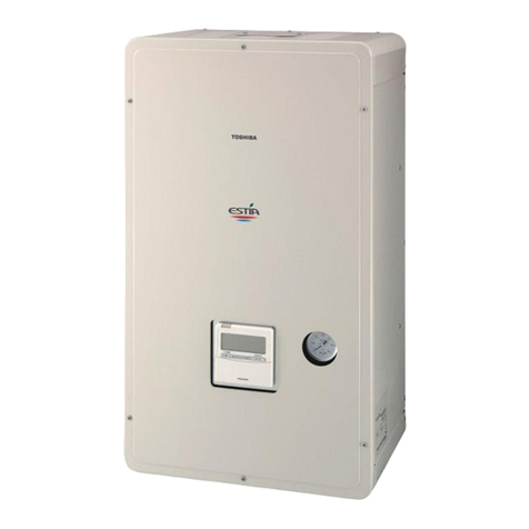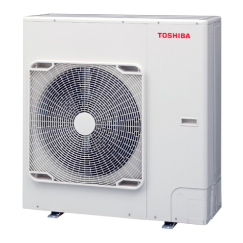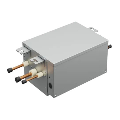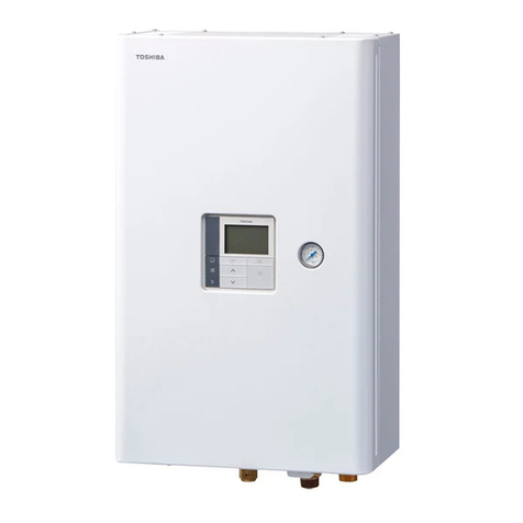
Monobloc Outdoor Unit Service Manual
3
8.2.7. Boiler control.........................................................................................................................................41
8.2.8. Domestic Hot Water Priority ................................................................................................................42
8.2.9. Anti-Legionella Control.........................................................................................................................43
8.2.10. Night Mode.............................................................................................................................................44
8.2.11. Water Freeze Protection.......................................................................................................................44
8.2.12. Home Anti-freeze protection................................................................................................................45
8.2.13. Auto / climatic curve operation............................................................................................................46
8.2.14. Summer mode control..........................................................................................................................50
8.2.15.Floor Drying Mode.................................................................................................................................50
8.2.16. Water Pump logic..................................................................................................................................51
8.2.17. Flow Switch Control..............................................................................................................................57
8.3. OVERRIDE LIST.................................................................................................................................................57
8.3.1. SYSTEM MODE OVERRIDE [P047] .....................................................................................................57
8.3.2. CAPACITY OVERRIDE [P064]..............................................................................................................58
8.3.3. Water Pump override [P081] ................................................................................................................60
8.3.4. Backup Override [P091]........................................................................................................................61
8.3.5. DHW Override [P202]............................................................................................................................62
8.4. INVERTER CONTROL LOGIC................................................................................................................................63
8.4.1. Compressor short cycling protection.................................................................................................63
8.4.2. Minimum compressor run time............................................................................................................63
8.4.3. Two-way Valve Control.........................................................................................................................63
8.4.4. Coil Heating Control..............................................................................................................................64
8.4.5. Superheat Control.................................................................................................................................65
8.4.6. Defrost logic ..........................................................................................................................................66
8.4.7. Outdoor fan control...............................................................................................................................67
9. METHOD OF DEFECT ANALYSIS........................................................................................................................70
9.1. MATTERS TO BE CONFIRMED FIRST.....................................................................................................................70
9.1.1. Initial check items .................................................................................................................................70
9.1.2. Check the power supply voltage.........................................................................................................70
9.1.3. Check for any miss-wiring of the connection cables........................................................................70
9.1.4. About the installation of the temperature sensor..............................................................................70
9.2. NON-DEFECTIVE OPERATION (PROGRAM OPERATION –NO ERROR CODE).............................................................70
9.3. OUTLINE OF THE DETERMINATION DIAGRAM ........................................................................................................71
9.3.1. Procedure of defect diagnosis.............................................................................................................71
9.3.2. How to determine the Alarm on the remote controller......................................................................71
9.3.3. How to cancel a check code ................................................................................................................72
9.3.4. How to determine the defect error by inverter board LED display..................................................72
9.3.5. How to diagnose by error code ...........................................................................................................75
9.4. DIAGNOSIS FLOW CHART FOR EACH ERROR CODE...............................................................................................79
9.4.1. Monobloc outdoor unit failure detection............................................................................................79
9.4.2. Temperature sensor, temperature – resistance characteristic tables.............................................95
10. PARAMETER DETAILS.....................................................................................................................................96
10.1. PARAMETER TABLES .....................................................................................................................................96
10.1.1. Service tables........................................................................................................................................97
10.1.2. Configuration tables .............................................................................................................................98
10.1.3. Display tables ......................................................................................................................................107
10.1.4. Maintenance tables.............................................................................................................................114
10.1.5. Setpoint tables.....................................................................................................................................120
10.1.6. POC tables ...........................................................................................................................................121
11. JBUS / MODBUS DETAILS .............................................................................................................................123
11.1. JBUS /MODBUS CONTROLLER ....................................................................................................................123
11.2. JBUS /MODBUS PARAMETER LIST...............................................................................................................123
12. MAIN COMPONENTS REPLACEMENT..........................................................................................................131
