Total Tools TTi TTIVP1000V User manual

24/90 1000V
VOLTAGE DETECTOR
PART NO: TTIVP1000V
(..151479)
OPERATING
INSTRUCTIONS

224/90 1000V VOLTAGE DETECTOR
CONTENTS
INTRODUCTION .........................................................................................................3
• Intended Use......................................................................................................................3
GENERAL SAFETY ......................................................................................................3
SAFETY INSTRUCTIONS............................................................................................4
• Safe Operation and Standards .......................................................................................4
• Electrical Symbols.............................................................................................................5
EXTERNAL OVERVIEW .........................................................................................................6
TECHNICAL SPECIFICATIONS..................................................................................6
OPERATING INSTRUCTIONS....................................................................................7
WARRANTY INFORMATION .....................................................................................8

3OPERATING MANUAL
INTRODUCTION
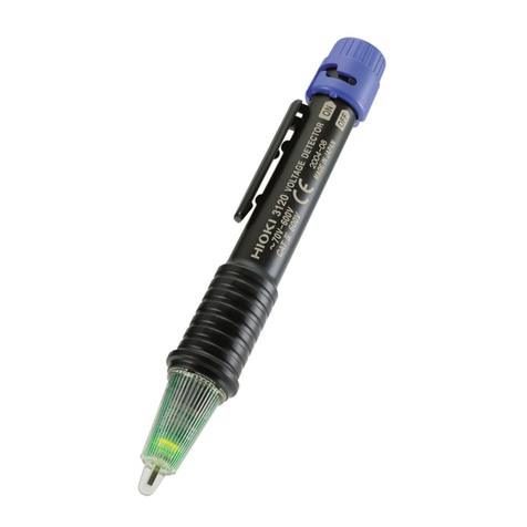
The TTIVP1000V voltage detector is a non-contact voltage detector with a built-in ashlight
and visual and audio alarm. The CAT IV 1000V safety class ensure users’safety.
INTENDED USE
The voltage detector is to be used only for electrical inspection within the specications the
device is rated for. Failure to use the device within the specications may result in serious injury
or death.
GENERAL SAFETY
Prior to using voltage detector, please read the product manual and ensure you have a solid
understanding of the machines functions and features.
CAUTION
!Upon rst use of the device, ensure the unit functions properly and
you’re familiar with all the functions.
WARNING
!
The warnings, cautions, and instructions discussed in this instruction
manual cannot cover all possible conditions or situations that could
occur. It must be understood by the operator that common sense and
caution are factors that cannot be built into this product, this must be
supplied by the operator.

424/90 1000V VOLTAGE DETECTOR
SAFETY INSTRUCTIONS
SAFE OPERATION AND STANDARDS
Anyone using this instrument should be knowledgeable and trained about the risks involved
with measuring voltage, especially in an industrial setting, and the importance of taking safety
precautions and of testing the instrument before and after using it to ensure that it is in good
working condition.
!WARNING
Please carefully read and fully understand the warning and operating
instruction before use. If the equipment is used in a manner not
specied by the manufacturer, the protection provided by the
equipment may be impaired.
Do not rely on the device to detect the presence or absence conductor
for safety purposes. This device is not suitable to determine if a circuit
is hazardous.
• Test the device on a known live source within the rated AC voltage range before and after use to
ensure it’s in good working.
• Do not use the device if it appears damaged or is not working properly.
• Do not attempt to detect voltage higher than 1000V.
• Use caution when working with voltage above AC 30V R.M.S, 42Vpeak or DC 60V. Such voltage
poses a shock hazard.
• Clean the device with a damp cloth. Do not use abrasives or solvents.
• There may still be voltage present even when there’s no visual or audio alarm on. The device
indicates active voltage in the presence of AC electric elds of sucient strength emanating from
the conductor. If the eld strength is low, the device may not provide indication of live voltages.
Lack of an indication occurs if the device is unable to sense the presence of the electric eld which
may be inuenced by several factors such, but not limited to shielded wires, type of insulation,
distance from the voltage source, socket design condition of the device and batteries. If there are
uncertainties, use other methods to verify the voltage.
• Do not assume neutral or ground wires are safe to touch. Incorrect or poorly connected circuits
may cause wires to be electrically charged, causing injury or death.
• Replace the batteries when low battery indication appears to avoid false readings that can lead to
electrical shock.
• Remove the alkaline batteries if the device is not used for an extended period of time, or if stored in
temperatures above 50 °C. If the batteries are not removed, battery leakage may result.
• Hold the device behind the NCV sensor, see page 6 for more detail.
• Comply with local and national safety regulations and requirements. Use personal protective
equipment such as approved rubber gloves, face protection, and ame-resistant clothing to
prevent shock and arc blast injury where hazardous live conductors are exposed.
• The detector will not detect and voltage if:
a. The wire is shielded.
b. The operate is not connected with the ground or isolated from an eective ground.
c. The voltage is DC (Direct Current)

5OPERATING MANUAL
• The detector may not detect any voltage if:
a. The operator does not hold the detector.
b. The operator is wearing gloves.
c. The wire under test is partially buried or in a grounded metal conduit.
d. The magnetic eld generate by the voltage source is blocked, suppressed or interfered with.
e. The frequency of the voltage being detected is not a perfect sine wave and may be
distorted by harmonics.
f. The detector is used outside of the operating specications (see technical specications
for details)
ELECTRICAL SYMBOLS
Double insulation
Warning
AC (alternating current)
CAT IV
This tool is applicable to test and
measure circuits connected at the source
of the building low-voltage MAINS
installations
This symbol signies product complies
with Australian requirements
Do not recycle

624/90 1000V VOLTAGE DETECTOR
EXTERNAL OVERVIEW
1. NCV Sensor
3.
4.
6.
5.
7.
2.
1.
8.
2. Flashlight
3. Signal sensing LED
4. Mode status indicator
(red/low, green/high)
5. Power button
6. Flashlight button
7. Pocket clip
8. End of the detector
(slide o to install/
remove battery
TECHNICAL SPECIFICATIONS
AC Voltage range 90~1000V AV (red indicator)
24~1000V AV (green indicator)
Frequency Range 50Hz/60Hz
Alarm Mode Audio/visual
Flashlight White spotlight
Auto Power O Approximately 5min
Low Battery Indication Yes
Safety Class CAT IV
Operating Temperature 0°C~40°C
Storage Temperature -20°C~50°C
Humidity <80% (non condensing)
Altitude <2000m
Battery 1.5V AAA x2
Product Size 150 x 18 x 23mm
Weight 50g (Approximately)
Standards IEC 61010
AS/NZS CISPR 11

7OPERATING MANUAL
OPERATING INSTRUCTIONS
TURNING ON THE DETECTOR
Press of the power button to turn the device on. The buzzer will beep twice, and a red light
will appear on the status indicator - the device is now ready for use. The default AC voltage
detection range is 90-1000V.
TURNING ON/OFF FLASH LIGHT
Press the ashlight button to turn on/o the ashlight. The ashlight will automatically turn o
when the detector is inactive for 5 minutes.
AC VOLTAGE DETECTION
Place the NCV sensor head near the test object. When AC voltage is detected, the red LED in the
NCV sensor head will light up and the buzzer will beep. The buzzer and LED ash will increase
in frequency when the detector gets close to the test object.
DETECTIONS RANGE SELECTION
•When the detector is on, the default mode is high voltage mode. With the detection range
of 90-1000V. This is signied by the red light on the mode status indicator.
•Short press of the power button to enter into low voltage mode. The mode status indicator
will be green, and the device will make a buzzing sound to indicate it’s in low voltage
mode. Low voltage detection range is 24-100V. In low voltage mode, the detector is more
sensitive to electrical interference/noise. It is advised to only use low voltage mode during
within a weak electrical environment.
AUTO POWER OFF
The voltage detector will auto power o when it is not used within 5 minutes.
TURNING OFF THE VOLTAGE DETECTOR MANUALLY
Press and hold the power button for 2 seconds to turn the device o. The device is o after a
long beep.
LOW BATTERY INDICATION
When the battery voltage is lower than 2.4V, the indicator light will turn on. Replace with two
AAA batteries.
BATTERY REPLACEMENT
Removing the end of the detector to replace batteries according to the correct polarity.

V3
WARRANTY INFORMATION
This warranty is provided by Total Tools (Importing) Pty Ltd of 20 Thackray Road,
Port Melbourne VIC 3207. Phone: 03 9261 1900 (we, us, our).
Express Warranty
Subject to the exclusions set out below, we warrant that this product will be free from defects
in materials or workmanship for 12 months from the date of purchase.
The benets conferred by this warranty are in addition to all rights and remedies which you
may be entitled to under the Australian Consumer Law, and any other statutory rights you may
have under other applicable laws. This warranty does not exclude, restrict or modify any such
rights or remedies.
Warranty exclusions
This express warranty does not apply where a defect or other issue with the product is caused
by normal wear and tear, misuse or abuse of the product.
Consumer guarantees
Our goods come with guarantees that cannot be excluded under the Australian Consumer Law.
You are entitled to a replacement or refund for a major failure and for compensation for any
other reasonably foreseeable loss or damage.
You are also entitled to have the goods repaired or replaced if the goods fail to be of acceptable
quality and the failure does not amount to a major failure.
Warranty claims
To make a claim under this warranty, you must bring the product along with the proof of
purchase and any other documentary evidence which you think is relevant to the Total Tools’
place of purchase where the claim will be handled on our behalf. Any cost incurred by you in
bringing the product to the place of purchase will be borne by you.
To make a claim under this warranty, the product and proof of purchase must be returned to
the Total Tools place of purchase during the warranty period specied above.
If your warranty claim is accepted, we (or the Total Tools store that handles the claim on our
behalf) will, at our discretion, repair or replace the product, or refund money to you and take
back the product.
Table of contents
