TOUGH-WORKS TDS-200CL User manual
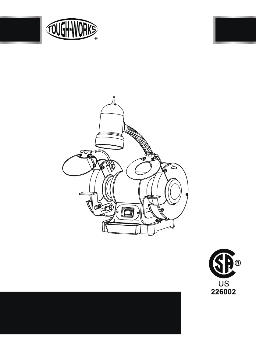
8 IN. BENCH GRINDER
WITH FIEXIBLE WORKLIGHT
INSTRUCTION
MANUAL
IMPORTANT:
For your own safety, read and follow all of the Safety
Guidelines and Operating Instructions before operating
this product.
TDS-200CL

2
TABLE OF CONTENTS
SPECIFICATIONS
TABLE OF CONTENTS
TABLE OF CONTENTS ...............................................................................................
2
SAFETY GUIDELINES ................................................................................................
5
PACKAGE CONTENTS ..............................................................................................
6
KEY PARTS DIAGRAN
..................................................................................................
7
ASSEMBLY/MOUNTING
........................................................................................
8
OPERATION .................................................................................................................
9
MAINTENANCE ............................................................................................................
10
TROUBLESHOOTING GUIDE .....................................................................................
12
EXPLONED VIEW .........................................................................................................
13
PARTS LIST ..................................................................................................................
14
WARRANTY ..................................................................................................................
15
TDS-200CL
SPECIFICATIONS .......................................................................................................
2
Motor:120 V AC, 60 Hz, 4.8A, 3/4 HP
Wheel Size:8 x 1" (20.3 x 2.5 cm) with 5/8"
(1.6 cm) arbour
Speed:3450 RPM (no-load)
Wheels: 36- and 60-grit
Weight: 29 lb 2 oz (13.2 kg)

SAFETY GUIDELINES
3TDS-200CL
• Always wear safety glasses complying with
OSHA/ANSI requirements Z87.1.
• Wear a mask or respirator when dust is
generated.
• Keep bystanders out of the work area while
operating the tool.
• Always ensure that the work area is clear of
any flammable materials, liquids or gasses,
because the use of this tool may create sparks.
•Wheel guards and eye shields must be properly
adjusted and tightened.
• During each start-up, stand to one side of
the grinder and switch it on. Let the grinder
operate at full speed for approximately one
minute so that any undetected flaws or cracks
will become apparent.
• Use only 40 W (max.) bulbs on the work light.
• Use only 8” wheels suitable for 3450 RPM
or over.
• Keep guards in place and working properly.
• Keep hands clear of grinding wheels.
•Always make sure wheels are properly mounted.
• Secure the tool when working to prevent
unexpected movement.
• Never reach behind or beneath the grinding
wheels.
• Unplug from power supply before adjusting
or servicing. The grinding wheels continue
to rotate after the tool is switched off. Always
allow wheels to stop before adjusting or
servicing.
• To avoid electric shock, DO NOT use in damp
conditions or expose to rain.
Failure to observe any of the following
instructions could result in severe
personal injury to tool user and bystanders
or cause damage to tool and property!
Read, understand and observe all
instructions in this manual before
using or operating the tool for which
it is written and supplied. Ensure that
anyone who is to use the tool has read
and understood the instructionsprovided.
•When fitting a new grinding wheel, always
check that the stated maximum RPM meets
or exceeds that stated on the grinder. Also
check the new wheel for damage, such as
flaws or cracks. If the wheel appears
satisfactory, fit it to the grinder.
• When a new grinding wheel has been
fitted, stand to one side of the grinder and
switch it on.
Let the grinder operate at full speed for
approximately one minute so that any
undetected flaws or cracks will become
apparent.
• Use only accessories that are recommended
by the manufacturer for your model.
•DO NOT attempt to cut anything with the
grinding wheel.
• Grounded tools must be plugged into an outlet
that has been properly installed and grounded
in accordance with all local codes and ordinances.
Never remove the grounding prong from the plug
or modify it in any way. Do not use adaptor plugs.
If in doubt as to whether the outlet is properly
grounded, consult a qualified electrician.
• Do not use the tool when tired or under the
influence of drugs, alcohol or medication.
• Do not wear gloves, neckties, jewellery or loose
clothing when using tool. Keep hair tied back.
• Ensure the power switch is off prior to plugging
in the tool.
Replace cracked grinding wheels
immediately.
• Do not overtighten spindle nuts.
• Spacing between tool rests and wheels should
be set to 1/8” or less; hold workpiece firmly
against tool rest.
• Service on thesetools should only be performed
by an authorized, qualified technician.
• Failure to comply with these warnings may
result in serious personal injury.
• There is a risk of injury due to accidental starting;
do not use this tool in an area where children
may be present.

4
TDS-200CL
General Tool Safety Warnings
Read all safety warnings and instructions.
Failure to follow the warnings and
instructions may result in electric shock,
fire and/or serious injury.
Save all warnings and instructions for
future reference.
9.
USE PROPER EXTENSION CORD.
Make sure your extension cord is in good
condition. When using an extension cord,
be sure to use one heavyenough to carry
the current your product will
draw.
An
undersized cord will cause a drop in
line voltage resulting in loss of power and
Table A shows the correct size to use
depending on cord length and nameplate
ampere
rating.
10.WEAR PROPER APPAREL.
Do not wear
loose
clothing, neckties, rings,
bracelets, or other jewelry which may get
caught in moving parts. Nonslip footwear
is recommended.
Wear protective hair covering to contain
long hair.
11.ALWAYS USE SAFETY GLASSES.
Alsouse face ordust mask if cutting operation
Everyday eyeglasses only have impact
resistant lenses, they are NOT safety
12.SECURE WORK.
Use clamps or a vise to hold
work when
practical. It’s safer than using your hand
and it frees both hands to operate tool.
13.DON’T OVERREACH.
Keep proper footing and balance at all
times.
1. KEEP GUARDS IN PLACE and in
working order.
2. REMOVE ADJUSTING KEYS AND
WRENCHES.
Form habit of checking to see that keys
and adjusting wrenches are removed
from tool before turning it on.
3. KEEP WORK AREA CLEAN.
Cluttered areas and
benches invite
4. DON’T USE IN DANGEROUS
ENVIRONMENT.
Don’t use power tools in damp or wet
locations, or
expose them to rain. Keep
5. KEEP CHILDREN AWAY.
All visitors should be kept safe distance
6. MAKE WORKSHOP KID PROOF with
padlocks, master switches, or by
7. DON’T FORCE TOOL.
It will do the job better
and safer at the
8. USE RIGHT TOOL.
Don’t force tool or attachment to do a
job for which it was not designed.
accidents.
work area well lighted.
from work area.
removing starter keys.
rate for which it was designed.
overheating.
is dusty.
glasses.
14.MAINTAIN TOOLS WITH CARE.
Keep toolssharp and clean for best and
safest performance. Follow instructions for
lubricating and changing accessories.
15.DISCONNECT TOOLS
Before servicing;
when changing accessories,
such as blades, bits, cutters, and the like.
16.REDUCE THE RISK OF UNINTENTIONAL
STARTING.
Make sure switch is in
off position before
plugging in.
17.USE RECOMMENDED ACCESSORIES.
Consult the owner’s manual for recommended
accessories. The use of improper
SAFETY GUIDELINES
TableA: RECOMMENDED MINIMUM WIRE GAUGE
FOR EXTENSIONCORDS
(
120VOLT)
NAMEPLATE
AMPERES
(at full load)
EXTENSION CORD
0 – 6 18 16 16 14
6.1 – 10 18 16 14 12
10.1 – 12 16 16 14 12
12.1 – 16 14 12 Do not use.
5TDS-200CL
Before You Start – Electrical
• Always wear eye protection that complies
with a recognized standard (CSA or ANSI;
for example: ANSI Z87.1)
• Wear a mask or respirator when dust is
generated.
• Keep bystanders out of the work area
while operating the tool.
• Always ensure that the work
area is clear of any flammable materials,
liquids or gases,because the use of this tool
may create sparks.
• Do not wear loose clothing or jewellery.
Keep hair tied back.
• Replace cracked grinding
wheels immediately..
• Do not overtighten spindle nuts.
• Adjust tool rests whenever necessary to
maintain a distance of 1/8” (3.2 mm) from
the grinding wheel.
• NEVER grind on the side of the wheel.
Grind on the face of the wheel only.
• NEVER apply pressure to the workpiece
when the grinding wheel is cold. Allow the
wheel to warm up by applying the workpiece
gradually.
• NEVER use the grinder without the wheel
guards. Keep thumbs andfingers away
from the wheel.
Before You Start - Safety
In the event of a malfunction or short circuit,
grounding provides the path of least resistance
for electrical current, and reduces the risk of
electric shock for the operator. This tool is
equipped with an electric cord that has an
equipment grounding conductor and a grounding
plug. The plug must be plugged into a matching
outlet that is properly installed and grounded
in accordance with all local codes and or
dinances.
DO NOT MODIFY THE PLUG PROVIDED.
If it will not fit the outlet, have the proper outlet
installed by an electrician.
IMPROPER CONNECTION of the equipment
grounding conductor can result in increased
risk of electric shock. The conductor with the
green insulation (with or without yellow stripes)
is the equipment grounding conductor. If repair
or replacement of the electric cord or plug is
necessary, DO NOT connect the equipment
grounding conductor to a live terminal.
CHECK with a qualified electrician or service
personnel if you do not completely understand
the grounding instructions, or if you are not
sure if the tool is properly grounded.
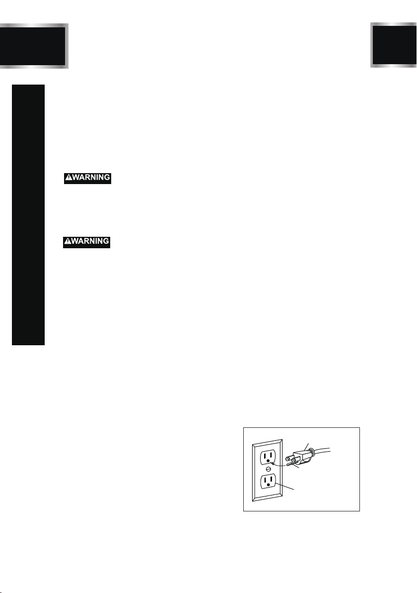
3-Pronged Plug
Properly Grounded
3-Hole Receptacle
Grounding Prong
This tool is intended for use on a circuit
that has align outlet that looks like the one
illustrated. The original tool has a grounding
plug that looks like the plug illustrated.
ELECTRICAL SAFETY
SAFETY GUIDELINES
6
TDS-200CL
C
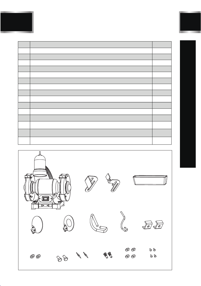
PACKAGE CONTENTS
No. Description Qty.
1
2
3
4
5
6
7
8
Bench grinder
Left work rest
Right work rest
Coolant tray
Plain eye shield assembly
Magnify eye shield
Left eye shield support
Right eye shield support
Bracket
Flat washer D6
Hex bolt M6X14
Spark deflector
Star-head screw+flat washer M5X10
Flat washer D8
Hex bolt M8X8
1
1
1
1
1
1
1
1
2
2
2
2
2
4
4
9
10
11
12
13
14
15
1
2 3 4
56789
10 11 12 13 14 15

BD4603
7TDS-200CL
KEY PARTS DIAGRAN
Lamp on/off switch
Lamp
Spark deflector
Plain
eye shield
Grinding
wheel 36#
Left
work rest
Switch
Magnify
eye shield
Grinding
wheel 60#
Right
work rest
Base Water tray

8
TDS-200CL
ASSEMBLY/ MOUNTING
Before attempting to use this grinder,
it must be properly mounted to a workbench
or grinding stand.
Using two long bolts, washers, lock-washers
and nuts, as shown (not supplied), secure the
grinder to the workbench.(Figure A)
Work bench
Flat washer
Hex nut
Bolt
Flat
washer
Fit the eye shield to the mount rod. Mount
the left and right shield rods to the inside of
the wheel guards using hex bolts.(Figure B)
Figure A
Figure B
Attach the left eye shield mounting rod
to the bench grinder using the bracket,
flat washer and bolt supplied.(Figure C)
Figure C

BD4603
9TDS-200CL
OPERATION
Bench grinders vibrate. Grinder movement
during high-speed rotation may cause
injury or damage to the workpiece or operator.
Mount the grinder securely to a sturdy
workbench or grinding stand.
The eye shield should move freely when
being adjusted, but stay in place when
the screw is tightened.
8INCH Bench Grinder is ideal for use in sharpening
chisels, axes and other woodcutting tools. It is also
useful for repairing tips on screwdrivers and drill
bits or for removing excess metal burrs from pieces
of cut metal.
With the proper accessories, this tool can be used
for cleaning metal surfaces using a wire brush or
for buffing and polishing using a cloth wheel.
The rocker I/O power switch is located on the front
of the grinder.
START-UP
Press the side marked “I” to turn the grinder on.
SHUT-DOWN
Press the side marked “O” to turn the grinder off.
10
TDS-200CL
MAINTENANCE
• Always keep the workpiece moving across the
face of the grinding wheel. Grinding continuously
on the same spot on the wheel will cause grooves
to be worn into the wheel. The wheel may crack
or become damaged more easily, and grinding of
other objects will be difficult.
• If the workpiece becomes hot, dip it into water or
oil to cool it.
• Always grind on the face of the wheel (around the
diameter), NEVER on the sides. Side pressure on
grinding wheels can cause cracking and damage.
• If the face of the grinding wheel is worn unevenly,
becomes grooved, or is no longer smooth and
flat, the wheel should be reshaped with a dressing
tool (not supplied).
• If the diameter of the grinding wheel is no longer
round, the wheel should be reshaped with a dre-
ssing tool or replaced.
• If the surface of the wheel becomes loaded and
dull with workpiece material, the wheel should be
cleaned with a dressing tool.
• After reshaping, always readjust the tool rests and
spark arrestors.
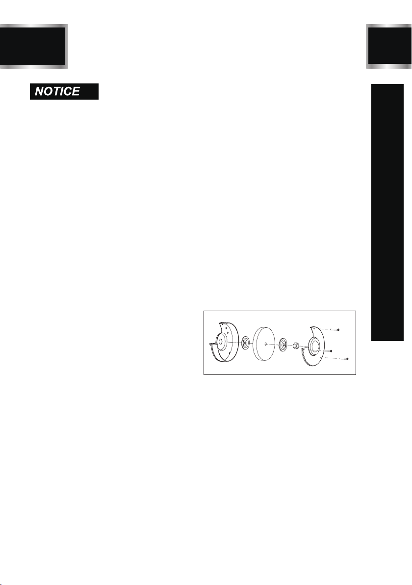
Installing or Changing the Wheel
When grinding, metal objects become heated
quickly. It is important to keep moving the object
back and forth across the face of the grinding
wheel and to cool the object frequently using the
coolant tray.
Work-light Bulb Replacement
When the light bulb is worn out and will no longer
work, purchase a replacement bulb. To replace,
gently push the light bulb into the socket and
turn clockwise. Uses Max 40 W anti-vibration
light bulb.
Installing or Changing the Wheel
1. Use a screwdriver to loosen the wheel cover
screws and push counter-clockwise to remove
the wheel cover.
2. Fit an appropriately sized wrench on the
spindle hex nut.
3. Loosen the wheel nut in a clockwise dire-
ction for the left side and a counter-clock
wise direction for the right side.
4. Remove the outer flange and grinding wheel.
To remove the hex nut, turn the wrench
and nut until the wrench is resting on the
workbench behind the tool.
5. Inspect the new wheel carefully to ensure
there are no cracks, chips or other damage.
6. Wipe the flange surfaces clean, and install
the new wheel, flange and the spindle hex
nut.
7. To install a new grinding wheel, reverse the
above procedure.
8. Be sure the grinding wheel and outer flange
are properly seated on the spindle shaft.
9. Replace the wheel cover and reposition the
tool rest.

BD4603
11 TDS-200CL
Problem Likely Solutions
Motor will
not start.
1. Low voltage.
2. Open circuit in motor or loose
connections.
3. Blown fuse or breaker.
Problem Possible Causes Likely Solutions
TROUBLESHOOTING
Motor will not
start-fuses or circuit
breakers tripping or
blowing.
Wheel dulls
quickly, grit
falls off.
1. Feed rate is too aggressive.
2. Wheel is soft.
3. Wheel diameter too small.
4. Bad wheel dressing.
5. Defective wheel bonding.
1. Decrease feed rate of workpiece into
grinding wheel.
2. Select a grinding wheel with a harder bond
of material.
3. Replace wheel.
4. Dress the wheel.
5. DO NOT USE – return wheel to point of
purchase.
1. Check power source for proper voltage.
2. Inspect all lead connections on motor for
loose or open connections.
(Send for servicing)
3. Change fuse or reset breaker.
(send for servicing)
1. Short circuit in line, cord or
plug.
2. Short circuit in motor or loose
connections.
3. Incorrect fuses or circuit
breakers in power line.
1. Inspect cord or plug for damaged
insulation and shorted wires.
2. Inspect all connections on motor for loose
or shorted terminals and/or worn insulation.
3. Install correct fuses or circuit breakers or
switch tool to an appropriately sized circuit.
Motor overheats.
1. Motor overloaded.
2. Extension cord too long and of
insufficient gauge (weight).
1. Reduce load on motor.
2. Utilize an extension cord of appropriate
gauge and length or plug tool directly into
outlet.
Motor stalls
(resulting in blown
fuses or tripped
circuit).
1. Short circuit in motor or loose
connections.
2. Low voltage.
3. Incorrect fuses or circuit
breakers in power line.
4. Motor overload.
1. Inspect connections on motor for loose or
shorted terminals or worn insulation.
(Send for servicing)
2. Correct low voltage conditions (for example:
improper extension cord length and/or
gauge).
3. Install correct fuses or circuit breakers or
plug tool into an appropriate circuit, matched
to an appropriate fuse or breaker.
4. Reduce the load on the motor.
Wavy condition
on surface of
workpiece.
1. Machine vibrating.
2. Workpiece not being held
firmly.
3. Wheel face uneven.
4. Wheel is too hard.
1. Ensure machine is securely mounted on a
solid surface.
2. Use a holding device to firmly retain the
workpiece.
3. Dress the grinding wheel.
4. Use softer wheel, or reduce the feed rate.

12
BD4603 TDS-200CL
Problem Likely Solutions
Problem Possible Causes Likely Solutions
Machine slows
when operating. 1. Feed rate too great.
1. Reduce the rate at which the workpiece is
fed into the working area of the tool
(grinding wheel).
Lines on surface
of workpiece.
Burning spots or
cracks in the
workpiece.
1. Impurity on surface of wheel.
2. Workpiece not being held
tightly.
1. Improper type of grinding
wheel.
2. Improper feed rate.
3. Coolant required.
1. Dress the grinding wheel.
2. Use a holding device to more firmly retain
the workpiece.
1. Try wheels with softer bond or coarser grit.
2. Slow down the rate at which the workpiece
is fed into the wheel.
3. Introduce coolant.
Wheel dulls
quickly, grit
falls off.
Wheel clogs and
workpiece shows
burn marks.
1. Feed rate is too aggressive.
2. Wheel is soft.
3. Wheel diameter too small.
4. Bad wheel dressing.
5. Defective wheel bonding.
1. Wheel is too hard.
2. Feed rate is too slow.
3. Bad wheel dressing.
4. Coolant required.
1. Decrease feed rate of workpiece into
grinding wheel.
2. Select a grinding wheel with a harder bond
of material.
3. Replace wheel.
4. Dress the wheel.
5. DO NOT USE – return wheel to point of
purchase.
1. Select a grinding wheel with a softer bond
of material.
2. Increase the feed rate of the workpiece into
the grinding wheel.
3. Dress the wheel.
4. Introduce coolant.
TROUBLESHOOTING
BD4603
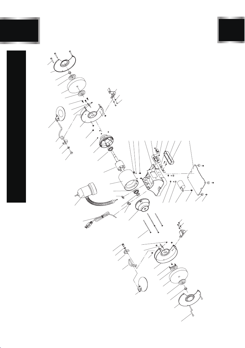
13 TDS-200CL
EXPLODED VIEW
51
32
31
4
4
6
30
15
50
34
35
41 42 38 43 44 45 46 46 48 49
403938
35
34
33
37
36
52
47
14
29
28
11
12
13
27
8
26
17
23
25
24
21 19
18
17
16
15
14
13
12
11
10
8
7
6
9
4
5
4
3
2
1
20
23
22

14
TDS-200CL
PARTS LIST
No. Qty.Description
1
2
3
4
5
6
7
8
9
10
11
12
13
14
15
16
17
18
19
20
21
22
23
24
25
26
Star-head screw M5X48
Left wheel guard cover
Hex nut, I type M16 left
Wheel flange
Grinding wheel 36#
Star-head screw+spring washer M5X10
Left wheel guard plate
Hex flange nut M5
Plain eye shield assy.
Left eye shield support
Bracket
Flat washer D6
Hex bolt M6X14
Spark deflector
Star-head screw+flat washer M5X10
Star-head screw+flat washer M5X155
End cap
Strain relief 6P4
Wave spring retainer D40
Cord & plug
Lamp assy
Flat washer D12
Bearing
Stator
Rotor
Hex flange nut M5
No. Qty.Description
3
1
1
4
1
6
1
6
1
1
2
2
2
2
2
4
2
1
2
1
1
1
2
1
1
4
27
28
29
30
31
32
33
34
35
36
37
38
39
40
41
42
43
44
45
46
47
48
49
50
51
52
Right wheel guard plate
Right eye shield support
Magnify eye shield assy.
Grinding wheel 60#
Hex nut, I type M16
Right wheel guard cover
Left work rest
Flat washer D8
Hex bolt M8X8
Hex bolt M8X20
Capacitor
Star-head screw+flat washer+
spring washer M4X8
Rubber washer
Star-head screw+ big flat washer M5X1
6
Cord bushing
Toothed lock washer D4
Base
Switch plate
Switch
Star-head screw M4X8
Coolant tray clip
Coolant tray
Base cover
Right work rest
Star-head screw M5X51
Spring washer D8
1
1
1
1
1
1
1
4
4
2
1
3
4
4
1
2
1
1
1
4
1
1
1
1
3
2

BD4603
15 TDS-200CL
WARRANTY
Having Problems ?
Give us a chance to help you before returning this product
Email :
After the phone:(844) 866-5687
ONE-YEAR LIMITED WARRANTY

Table of contents
Other TOUGH-WORKS Grinder manuals


