TOUGH-WORKS TDS-G200VLDB User manual
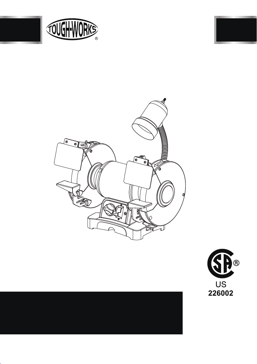
8 IN. VARIABLE SPEED
BENCH GRINDER WITH LIGHT
INSTRUCTION
MANUAL
IMPORTANT:
For your own safety, read and follow all of the Safety
Guidelines and Operating Instructions before operating
this product.
TDS-G200VLDB

2
TABLE OF CONTENTS
SPECIFICATIONS
TABLE OF CONTENTS
TABLE OF CONTENTS ...............................................................................................
2
SAFETY GUIDELINES ................................................................................................
PACKAGE CONTENTS ..............................................................................................
8
KEY PARTS DIAGRAN
..................................................................................................
9
ASSEMBLY INSTRUCTIONS........................................................................................
11
OPERATION .................................................................................................................
13
MAINTENANCE ............................................................................................................
14
TROUBLESHOOTING GUIDE .....................................................................................
15
EXPLONED VIEW .........................................................................................................
16
PARTS LIST ..................................................................................................................
19
WARRANTY ..................................................................................................................
20
ELECTRICAL SAFETY .................................................................................................
7
SPECIFICATIONS ......................................................................................................
2
TDS-G200VLDB
MOTOR POWER 3/4HP, 120V, 5A, 60Hz, 1Ph, Induction
MOTOR SPEED 2,000 - 3,400 RPM
GRINDING WHEEL SIZE 8” x 1” x 5/8”
WIRE WHEEL SIZE 8” x 5/8” x 5/8”
LIGHT (40W max.) 120V/60Hz
6

BD4603
SAFETY GUIDELINES
SAFETY GUIDELINES - DEFINITIONS
3
WARNING ICONS
Your power tool and its Instruction Manual may contain “WARNING ICONS”(a
picture)symbol intended to alert you to and/or instruct you how to avoid a potentially
hazardous condition). Understanding and heeding these symbols will help you operate
your tool
better and safer. Shown below are some of the symbols you may see.
SAFETY ALERT: Precautions that involve your safety.
DANGER: Indicates an imminently hazardous situation which, if not
avoided, will result in death or serious injury.
WARNING: Indicates a potentially hazardous situation which, if not
avoided, could result in death or serious injury.
CAUTION: Indicates a potentially hazardous situation which, if not
avoided,may result in minor or moderate injury.
NOTICE: Used without the safety alert symbol indicates potentially
hazardous situation which, if not avoided, may result in property damage.
WARNING
!
DANGER
!
CAUTION
!
NOTICE
TDS-G200VLDB
GENERAL SAFETY
Operating a Bench Grinder can be dangerous
if safety and common sense are ignored. The
operator must be familiar with the operation
of the tool. Read this manual to understand
this Bench Grinder. DO NOT operate this Bench
Grinder if you do not fully understand the
limitations of this tool. DO NOT modify this
Bench Grinder in any way.
BEFORE USING GRINDER
WARNING
!
To avoid serious injury and damage to the tool,
read and follow all of the Safety and Operating
Instructions before operating the Bench Grinder.
WARNING
!
1. Some dust created by using power tools
contains chemicals known to the State of
California to cause cancer, birth defects, or
other reproductive harm.
Some examples of these chemicals are:
• Lead from lead-based paints.
• Crystalline silica from bricks, cement, and
other masonry products.
• Arsenic and chromium from hemically treated
lumber.
Your risk from these exposures varies, depending
on how often you do this type of work. To reduce
your exposure to these chemicals: work in a well
ventilated area and work with approved safety
equipment, such as those dust masks that are
specially designed to filter out microscopic particles.
2. READ the entire Owner’s Manual. LEARN how
to use the tool for its intended applications.
3. GROUND ALL TOOLS.
If the tool is supplied with a 3-prong plug, it must
be plugged into a 3-contact electrical receptacle.
The 3rd prong is used to ground the tool and
provide protection against accidental electric shock.
DO NOT remove the 3rd prong. See Grounding
Instructions on page 7.
4. AVOID A DANGEROUS WORKING
ENVIRONMENT. DO NOT use electrical tools in
a damp environment or expose them to rain.
5. DO NOT use electrical tools in the presence of
flammable liquids or gasses.
6. ALWAYS keep the work area clean, well lit, and
organized. DO NOT work in an environment with
floorsurfaces that are slippery from debris,
grease, and wax.
7. KEEP VISITORS AND CHILDREN AWAY.
DO NOT permit people to be in the immediate
work area, especially when the electrical tool is
operating.

SAFETY GUIDELINES
4
TDS-G200VLDB
8.
DO NOT FORCE THE TOOL
to perform an
operation for which it was not designed. It
will do a safer and higher quality job by only
performing operations for which the tool
was intended.
9. WEAR PROPER CLOTHING.
DO NOT
wear loose clothing, gloves,
neckties, or jewelry. These items can get
caught in the machine during operations and
pull the operator into the moving parts.
The user must wear a protective cover on
their hair, if the hair is long, to prevent it from
contacting any moving parts.
10.
CHILDPROOF THE WORKSHOP AREA
by removing switch keys, unplugging tools
from the electrical receptacles, and using
padlocks.
11.
ALWAYS UNPLUG THE TOOL FROM THE
ELECTRICAL RECEPTACLE
when making
adjustments, changing parts or performing
any maintenance.
12.
KEEP PROTECTIVE GUARDS IN PLACE
AND IN WORKING ORDER.
13. AVOID ACCIDENTAL STARTING.
Make
sure that the power switch is in the “OFF”
position before plugging in the power cord
to the electrical receptacle.
14.
REMOVE ALL MAINTENANCE TOOLS
from the immediate area prior to turning“ON”
the Bench Grinder.
15.
USE ONLY RECOMMENDED ACCESSORIES.
Use of incorrect or improper accessories
could cause serious injury to the operator and
cause damage to the tool. If in doubt, check
the instruction manual that comes with that
particular accessory.
16.
NEVER LEAVE A RUNNING TOOL
UNATTENDED
. Turn the power switch to the
“OFF” position. DO NOT leave the tool until
it has come to a complete stop.
17.
DO NOT STAND ON A TOOL.
Serious injury
could result if the tool tips over, or you
accidentally contact the tool.
18.
DO NOT
store anything above or near the
tool where anyone might try to stand on the
tool to reach it.
19.
MAINTAIN YOUR BALANCE. DO NOT
extend
yourself over the tool. Wear oil resistant rubber
soled shoes. Keep floor clear of debris, grease
and wax.
20.
MAINTAIN TOOLS WITH CARE.
Always keep
tools clean and in good working order. Keep
all blades and tool bits sharp, dress grinding
wheels and change other abrasive accessories
when worn.
21.
EACH AND EVERY TIME, CHECK FOR
DAMAGED PARTS PRIOR TO USING THE
TOOL.
Carefully check all guards to see that they
operate properly, are not damaged, and
perform their intended functions. Check for
alignment, binding or breaking of moving parts.
A guard or other part that is damaged should
be immediately repaired or replaced.
22.
DO NOT OPERATE TOOL WHILE TIRED, OR
UNDER THE INFLUENCE OF DRUGS,
MEDICATION OR ALCOHOL.
23.
SECURE ALL WORK.
Use clamps or jigs to secure the work piece.
This is safer than attempting to hold the work
piece with your hands.
24.
STAY ALERT, WATCH WHAT YOU ARE
DOING, AND USE COMMON SENSE WHEN
OPERATING A POWER TOOL.
A moment of inattention while operating
power tools may result in serious personal
injury.
25.
ALWAYS WEAR A DUST MASK TO PREVENT
INHALING DANGEROUS DUST OR AIRBORNE
PARTICLES,
including wood dust, crystalline
silica dust and asbestos dust. Direct particles
away from face and body.
Always operate tool in well ventilated area
and provide for proper dust removal. Use
dust collection system wherever possible.
Exposure to the dust may cause serious and
permanent respiratory or other injury,including
silicosis (a serious lung disease), cancer, and
death. Avoid breathing the dust, and avoid
prolonged contact with dust.
Allowing dust to get into your mouth or eyes,

BD4603
5
or lay on your skin may promote absorption
of harmful material. Always use properly
fitting
NIOSH/OSHA
approved respiratory
protection appropriate for the dust exposure,
and wash exposed areas with soap and water.
26.
USE A PROPER EXTENSION CORD IN
GOOD CONDITION.
When using an extension
cord, be sure to use one heavy enough to
carry the current your product will draw. The
table on page 8 shows the correct size to use
depending on cord length and nameplate
amperage rating. If in doubt, use the next
heavier gauge.The smaller the gauge number,
the larger diameter of the extension cord. If
in doubt of the proper size of an extension
cord, use a shorter and thicker cord. An
undersized cord will cause a drop in line voltage
resulting in a loss of power and overheating.
TDS-G200VLDB
SPECIFIC SAFETY
INSTRUCTIONS FOR BENCH
GRINDERS
The operation of any grinder or power tool can
result in debris being thrown into your eyes,
which can result in severe and permanent eye
damage.
ALWAYS WEAR EYE PROTECTION.
Everyday
eyeglasses are
NOT
safety glasses.
ALWAYS
wear Safety Goggles (that comply with ANSI
standard Z87.1) when operating power tools.
Basic precautions should always be followed
when using your bench grinder. To reduce the
risk of injury, electrical shock, or fire, comply
with the safety rules listed below:
1.
ALWAYS USE THE EYE SHIELDS AND
WHEEL GUARDS
provided with the grinder.
2.
REPLACE A CRACKED OR DAMAGED
GRINDING WHEEL IMMEDIATELY. A
damaged wheel can discharge debris at
a high velocity towards the operator.
Carefully handle the grinding wheels since
they are abrasive. Prior to replacing a
grinding wheel, check it for cracks.
DO NOT
remove the blotter or label on both
sides of the grinding wheel. Tighten the spindle
nut just enough to hold the grinding wheel firmly
to the Bench Grinder.
DO NOT
over-tighten
the nut.
Excessive clamping force can damage the
grinding wheel. Only use the wheel flanges
provided with the grinder. When selecting a
replacement grinding wheel use only properly
sized wheels, and verify that the grinding wheel
has a higher R.P.M. rating than the maximum
R.P.M. of the Bench Grinder.
3.
THE DIAMETER OF THE GRINDING
WHEELS WILL DECREASE WITH USE
.
Adjust the tool rests and spark arrestors
to maintain a distance of 1/16” from the
wheel.
4.
DO NOT STAND IN FRONT OF THE BENCH
GRINDER WHEN STARTING IT.
Stand to one side of the Bench Grinder
and turn it “ON”. Wait at the side for one
minute until the grinder comes up to full
speed. There is always a possibility that
debris from a damaged grinding wheel
may be discharged towards the operator.
5.
THE BENCH GRINDER WILL PRODUCE
SPARKS AND DEBRIS DURING GRINDING
OPERATIONS.
Be sure that there are not any flammable
materials in the vicinity. Frequently clean
grinding dust from the back of the Bench
Grinder.
6.
NEVER FORCE THE WORK PIECE AGAINST
A GRINDING WHEEL,
especially if the wheel
is cold. Apply the work piece slowly, allowing
the grinding wheel an opportunity to warm
up. This will minimize the chance of wheel
breakage.
DO NOT
grind using the sides
of the grinding wheels.
DO NOT
apply
coolant directly to the grinding wheel.
7.
KEEP ALL WHEEL GUARDS IN PLACE. DO
NOT USE THE BENCH GRINDER WITH THE
WHEEL GUARDS REMOVED
.
8.
KEEP THE TOOL RESTS FIRMLY IN PLACE
AND TIGHTENED
. Use them to safely position
your material for grinding.
SAFETY GUIDELINES

6
TDS-G200VLDB
9.
ALWAYS USE A WHEEL DRESSER TO
RESURFACE THE FACE OF THE GRINDING
WHEEL.
10.
DRESS THE GRINDING WHEEL OFTEN.
This will keep the wheel surface flat and free of
nicks and residue/glaze.
11.
REMOVE ADJUSTING KEYS AND WRENCHES.
Form habit of checking to see that keys and
adjusting wrenches are removed from grinder
before turning it on.
12.
ALLOW THE GRINDER TO ATTAIN FULL
SPEED BEFORE BEGINNING WORK.
13.
NEVER STOP THE GRINDER BY FORCING
MATERIAL INTO THE WHEEL.
Let the grinder
stop rotating on its own.
14.
SECURE THE BENCH GRINDER
to a stand
or workbench to prevent sliding or tipping during
use. See page 12.
15.
FREQUENTLY
clean grinding dust from inside
of the guards and beneath the grinder.
16.
NEVER GRIND SMALL STOCK
without it being
properly supported on the tool rests,and held
by pliers or clamps.
17.
DO NOT FORCE THE TOOL
to perform an
operation for which it was not designed. It will
do a safer and higher quality job by only performing
operations for which the tool was intended.
SAFETY GUIDELINES
EXTENSION CORDS
Keep the extension cord clear of the working
area. Position the cord so that it will not get
caught on lumber, tools or other obstructions
while you are working with a power tool.
Check extension cords before each use. If
damaged replace immediately. Never use a tool
with a damaged cord, since touching the
damaged area could cause electrical shock,
resulting in serious injury.t
WARNING
!
WARNING
!
Use a proper extension cord. Only use cords
listed by Underwriters Laboratories (UL). Other
extension cords can cause a drop in line voltage,
resulting in a loss of power and overheating of tool.
When operating a power tool outdoors, use an
outdoor extension cord marked “W-A” or “W ”.
These cords are rated for outdoor use and reduce
the risk of electric shock.

ELECTRICAL SAFETY
BD4603
7
WARNING
!
TDS-G200VLDB
THIS TOOL MUST BE GROUNDED WHILE IN USE
TO PROTECT THE OPERATOR FROM ELECTRIC
SHOCK.
I
N THE EVENT OF A MALFUNCTION OR
BREAKDOWN,
grounding provides the path of least
resistance forelectric current and reduces the risk
of electric shock.This tool is equipped with an electric
cord that has an equipment grounding conductor and
a grounding plug. The plug MUST be plugged into a
matching electrical receptacle that is properly
installed and grounded in accordance with ALL local
codes and ordinances.
DO NOT MODIFY THE PLUG PROVIDED.
If it will not fit the electrical receptacle,have the proper
electrical receptacle installed by a qualified electrician.
IMPROPER ELECTRICAL CONNECTION
of the
equipment grounding conductor can result in risk of
electric shock. The conductor with the green insulation
(with or without yellow stripes) is the equipment
grounding conductor.
DO NOT
connect the equipment
grounding conductor to a live terminal if repair or
replacement of the electric cord or plug is necessary.
CHECK
with a qualified electrician or service personnel
if you do not completely under-stand the grounding
instructions, or if you are not sure the tool is properly
grounded.
USE ONLY A 3-WIRE EXTENSION CORD THAT HAS
A 3-PRONG GROUNDING PLUG AND A 3-POLE
RECEPTACLE THAT
ACCEPTS THE TOOL’S PLUG. REPLACE A
DAMAGED OR WORN CORD IMMEDIATELY.
This tool is intended for use on a circuit that has an
electrical receptacle as shown in
FIGURE A. FIGURE
A
shows a 3-wire electrical plug and electrical
receptacle that has a grounding conductor. If a properly
grounded electrical receptacle is not available, an
adapter as shown in FIGURE B can be used to
temporarily connect this plug to a 2-contact ungrounded
receptacle. The adapter has a rigid lug extending from
it that MUST be connected to a permanent earth
ground, such as a properly grounded receptacle box.
THIS ADAPTER IS PROHIBITED IN CANADA.
FIG. A
FIG. B

8
PACKAGE CONTENTS
No. Description Qty.
A
2
B4
C4
D1
E1
F2
G2
H1
TDS-G200VLDB
Fig. C
Grinder (not shown)
Eyeshield assembly, left
Eyeshield assembly, right
Wheel dresser
Tool rest support, left
Tool rest support, right
Spark arrestor, left
Spark arrestor,right
1
1
1
1
1
1
1
1
Description Qty.
I Carriage bolt M6 x 12
No.
Pan head screws w/
washers M5 x 10
Flat Washer M6
Tool rest,left
Tool rest,right
Eyeshield knob
Tool rest knob
Light Bulb (not shown)
J
K
L
M
N
O
P

BD4603
9
KEY PARTS DIAGRAN
TDS-G200VLDB
1
2
3
4
5
6
7
8 9 10
11
12
13
No. Description Qty.
11
22
32
42
51
62
74
81
LED Work Light
Eye Shield Adjustment Knob
Eye Shield Assembly
Wheel Cover
8” Grinding Wheel, 60 Grit
Tool Rest
Tool Rest Adjustment Knobs
Variable Speed Dial
Water Tray
On/Off Switch with Removable Key
8” Wire Wheel
Spark Arrester
Motor
1
1
1
1
2
9
10
11
12
13
Fig. D
10
TDS-G200VLDB
ASSEMBLY INSTRUCTIONS
THE MACHINE MUST NOT BE PLUGGED IN AND THE
POWER SWITCH MUST BE IN THE OFF POSITION
UNTIL ASSEMBLY OF THE PARTS AND ALL
ADJUSTMENTS ARE COMPLETE.
ASSEMBLE THE GRINDER PARTS
WARNING
!
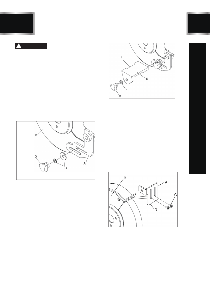
TOOL RESTS (Figs. E and F)
Tool Rests assemblies for use with the two different
wheels. The Left Side Tool Rest for the grinding wheel
is grooved to accept drill bits.The Right Side Tool Rest
for the wire wheel is entirely flat.
1. Assemble the Tool Rest Supports (A) to the inside
surface of the Wheel Covers (B) with the flat and
lock washers (C) and knobs (D) as shown. See
Figure E.
The illustrations show the assembly of the right tool
rest. The same process should be done for the left
tool rest.
2. Assemble the Tool Rests (E) to the Supports (F)
with the supplied flat washers (G) and Adjustment
Knobs (H) as shown. See Figure F.
3. Adjust each Tool Rest until its inside edge (I) is
1/16” from the wheel. Firmly tighten the hex bolts
and knobs holding the supports. See Figure F.
FIG. E
FIG. F
SPARK ARRESTORS (Fig. G)
1. Assemble the Spark Arrestors (A) to the front
surface of the Wheel Covers (B) with the pan
head screws and washers (C) as shown. See
Figure G.
2. Adjust each Spark Arrestor until the lower edge
(D) is1/16” from the wheel.Then firmly tighten
the pan head screws. See Figure G.
3. As the grinding wheel reduces in size from
use, re-adjust the spark arrestors so that their
lower edges maintain the safe 1/1t6”spacing
from the wheel.
FIG. G
EYE SHIELDS (Fig. H)
1. Assemble the Eyeshield (C) to the Spark
Arrestor (A) by inserting carriage head screw
( B ) through the Spark Arrestor and the
Eyeshield as shown. See Figure H.
2. Assemble the flat Washer (D) and Lock Knob
(E) to the carriage head screw and tighten
until the Eyeshield remains in the desired

11
ASSEMBLY INSTRUCTIONS
WARNING
!
position. See Figure H.
3. The eye shields should be positioned over
the wheels to protect the user against any
sparks or debris that may be thrown during
use.
4. Adjust the eye shield bracket and eye shield
into the desired position above the grinding
wheel, then tighten the knobs.
ALWAYS USE THE EYE SHIELDS AND WHEEL
GUARDS provided with the grinder.
FIG. H
WORK LIGHT
The Bench Grinder is provided with a Flexible
Work Light to assist in visibility of the workpiece.
To reduce the risk of fire, use a 120 volt, 40 Watt
or less Track Light Bulb, Type R20, medium
base or equivalent (included).
DO NOT use a light bulb that extends past the
end of the light housing.
The Flexible Work Light housing will remain hot
for a few minutes after turning it “OFF”. Avoid
contact with housing until it is cool.
WARNING
!
PERMANENT MOUNTING (Fig. I)
Use the mounting holes in the base of the grinder
to firmly attach grinder to a solid work surface
or grinder stand (mounting hardware and stand
not included). See Figure I.
To avoid serious injury, secure the Bench Grinder
to a solid work surface. If the Grinder is not
permanently mounted to a work surface, and
remains portable, the Grinder’s base should
be temporarily clamped to a table or board/
plywood. Make sure that the clamps do not
interfere with the tool rests, wheels or hinders
the movement of the user and the material
being ground during use.
If the Bench Grinder is not securely mounted,
it will have the ability to move or tip over during
grinding operations and possibly cause the
operator’s fingers to contact the grinding wheels.
FIG. I
WARNING
!
ALWAYS WEAR EYE PROTECTION!
Everyday eyeglasses are NOT safety glasses.
ALWAYS wear Safety Goggles (that comply
with ANSI standard Z87.1) when operating
power tools.
Hot sparks and debris are produced during
grinding and wire wheel operations. Wearing
a respirator or dust mask is recommended.
CAUTION
!
TDS-G200VLDB
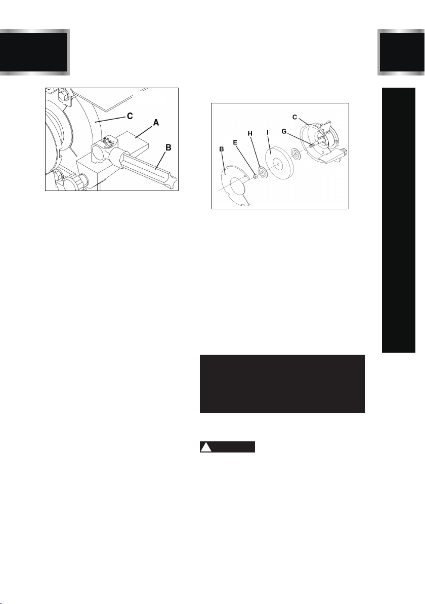
USING THE WHEEL DRESSER (Fig. J)
The Wheel Dresser is to be used to remove any
forward wobble, buildup up of material on the
grinding wheel, remove imperfections, and make
the corners of the grinding wheel square. See
Figure J.
12
BD4603 TDS-G200VLDB
FIG. J
DO NOT use the Wheel Dresser on the Wire
Wheel. It is for trueing abrasive wheels only.
1. Adjust tool rest (A) until it is in the flat
horizontal position as shown and 1/16”away
from the grinding wheel.
2. Turn “ON” the Bench Grinder, then turn the
Variable Speed Switch clockwise to your
desired speed setting.Let the grinding wheel
come up to a steady speed for one minute.
3. After the grinding wheel has gotten to a
steady speed, place the Wheel Dresser (B)
flat on the Tool Rest (A) with the serrated
dressing wheels facing the grinding wheel.
4. Firmly hold on to the handle of the Wheel
Dresser.
5. Move the Wheel Dresser forward until it
makes light contact with the grinding wheel
(C). After contact has been made, slide the
Wheel Dresser side to side across the Tool
Rest to dress the grinding wheel until the
edges of the grinding wheel are square
and the surface is clean.
6. After the dressing the grinding wheel, turn
“OFF” the Bench Grinder and let the grinding
wheel come to a complete stop. Allow the
grinding wheel to cool down for a period
of 10 minutes before use.
7. Inspect the grinding wheel for any irregularities
that still need to be dressed,or for and damage.
If there is damage to thewheel (cracks, major
chips missing), replace the wheel immediately.
8. The grinding wheel may now be slightly smaller
in diameter after dressing. Re-adjust the
tool rests and spark arrestors to maintain
a 1/16” clearance to the grinding wheel.
CHANGING THE GRINDING WHEEL(Fig. K)
Due to normal wear, both wheels will need to be
replaced occasionally.
1. Turn the power switch OFF and unplug the
power cord from its power source.
2. Rotate the eye shield up to access the tool rest.
3. Loosen the tool rest knob and rotate the tool
rest away from the grinding wheel.
4. Remove the Wheel Cover (B) by unscrewing
the fasteners that hold it in place.
5. Lightly push a wood wedge between the grinding
wheel and the guard to keep the shaft from turning.
Then use a crescent wrench to remove the arbor
hex nut.
FIG. K
NOTE: The left hand arbor hex nut (E) is left
hand threaded and is loosened by rotating it
clockwise. The right hand arbor hex nut is right
hand threaded and is loosened by rotating it
counter-clockwise.
6. Remove the Outer Wheel Flange (H) and then the
abrasive wheel (I) from the arbor shaft (G).
7. The new abrasive wheel to be put onto the grinder
must have a higher R.P.M. rating than the grinder’s
motor (3,450 RPM).The new abrasive wheel must
have the correct 8” outer wheel diameter and 5/8”
bore diameter asoriginal wheels.The labels on the
sides of the abrasive wheel must stay on.
DO NOT remove these labels. These labels or fiber
discs help spread the holding pressure of the
tightened nuts on the grinding wheel flanges.
CAUTION
!
OPERATION

BD4603
13 TDS-G200VLDB
8. Replace the abrasive wheel, outer wheel flange
and arbor hex nut.
NOTE:
The left hand arbor hex nut is left hand threaded
and is tightened by rotating it counter-clockwise. The
right hand arbor hex nut is right hand threaded and is
tightened by rotating it clockwise.
DO NOT OVER TIGHTEN
the arbor hex nut as this
may damage the abrasive wheel, wheel flanges and
cause serious injury to the operator.
9. Replace the wheel cover and secure it back in
place on the grinder with the fasteners that were
previously removed (step 4).
10.Run the new wheel at full speed for a few minutes
to ensure that it is rotating properly.
CAUTION
!
WIRE WHEEL or BUFFING WHEEL (Fig. L)
FIG. L
A wire wheel (A) or buffing wheel (not included) can
be used with your grinder.
Depending on the thickness of the wheel, you will
need to add one or more spacers (not included) to
allow the arbor hex nut (D) to tighten correctly. Figure
L shows the correct placement of the spacer (B).
NOTE: Spacers (B) should always go onto the
arbor shaft first. Always use the wheel flanges
(E) that come with the grinder for both wire
wheel and buffing wheels. See section CHANGING
THE GRINDING WHEEL for correct procedure
of changing wheels.
OPERATION

14
MAINTENANCE
MAINTENANCE OF THE BENCH
GRINDER
Turn the power switch “OFF” and unplug the power
cord from its power source prior to any maintenance.
LUBRICATION
The Bench Grinder has sealed lubricated bearings
in the motor housing that do not require any additional
lubrication from the operator.
CLEANING
With the Bench Grinder unplugged, rotate the wheels
slowly and inspect for any damage or trapped
debris. Periodically blow areas in and around the
grinder to keep the machine and work area clean.
WARNING
!
REPLACE
the abrasive or wire wheels if there is any
damage at all.
FAILURE
to replace a damaged wheel can cause
serious injury to the operator. Periodically check all
nuts and fasteners on the machine to make sure
that they are secure.
DO NOT USE FLAMMABLE MATERIALS
to clean
the Bench Grinder. A clean dry rag or brush is all
that is needed to remove dust and debris buildup.
CAUTION
!
CAUTION
!
WARNING
!
Repairs to the Bench Grinder should be performed
by trained personnel only.
Unauthorized repairs or replacement with non-
factory parts could cause serious injury to the operator
and damage to the Grinder.
TDS-G200VLDB

BD4603
15
TROUBLESHOOTING GUIDE
WARNING
!
TO PREVENT INJURY TO YOURSELF
or damage to the Bench Grinder, turn the switch to the “OFF”
position and unplug the power cord from the electrical receptacle before making any adjustments.
Motor does
not run
Motor does
not have full
power
Motor runs hot
Motor stalls
or runs slow
Fuses blow or
circuit breaker
trips
1. Machine not plugged in
2. Power switch in “OFF” position
3. Power switch or cord is faulty
4. Fuse or circuit breaker are open
5. Material wedged between wheel
and tool rest or guard
1. Incorrect line voltage
2. Motor capacitor has failed
1. Plug power cord into electrical receptacle
2. Lift switch to “ON” position
3. Replace switch or power cord
4. Overloaded electrical circuit
5. Turn grinder off, unplug power cord and
remove material.
1. Have a qualified electrician check
circuit for proper voltage.
2. Replace motor capacitor.
1. Motor is overloaded
2. Poor air circulation around motor
3. Overuse in high ambient
temperature room
1. Reduce pressure on work piece.
2. Remove any blockage around motor.
3. Reduceruntime to 20 minutes or less.
1. Motor is overloaded
2. Incorrect line voltage
3. Motor capacitor has failed
1. Reduce pressure on work piece.
2. Have a qualified electrician check
circuit for proper voltage.
3. Replace motor capacitor.
1. Motor is overloaded.
2. Overloaded electrical circuit.
3. Undersized fuse or circuit breaker.
4. Defective cord, plug or switch
creating a short circuit.
5. Undersized or excessive length
of extension cord, see page 6.
6. Material wedged between wheel
and tool rest or guard
1. Reduce pressure on work piece.
2. Reduce the amount of items on circuit
3. Replace with correct fuse or circuit
breaker.
4. Replace with new parts.
5. Use correct size and length of
extension cord.
6. Turn grinder off, unplug power cord
and remove material.
TDS-G200VLDB
16
BD4603
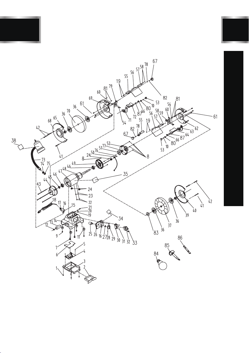
EXPLONED VIEW
TDS-G200VLDB

BD4603
17
ID Description Size Q’ty
PARTS LIST
1
2
3
4
5
6
7
8
9
10
11
12
13
14
15
16
17
18
19
20
21
22
23
24
25
26
27
28
29
30
31
32
33
34
Phillips screw+ flat washer (white) M4x6
Coolant tray
Coolant tray plate
PC board
Phillips screw (white) ST2.9x5
PC board cover
I type hex + spring washer (white) M8x22
Hex nut M5
Phillips screw+flat washer (white) M5x16
Spring washer D5
Rubber foot
Hex nut 4
Capacitor
Base
Cord clip fixing plate
Phillips screw (black) M5x8
Cord Clip
Power cord
Hex nut (black) M4
Knob 3/16 inch
Phillips screw (black) M4x16
Phillips screw+spring+flat washers M4x8
Out tooth locking washer D4
Cord bushing
Potential device
Switch Plate
Knob washer
Socket set screw M5x15
Variable Speed Knob
Switch guard board
Phillips screw M3x10
Locking switch
Switch safety key
Variable pointing label
4
1
1
1
2
1
2
8
4
2
4
1
1
1
1
4
1
1
5
1
1
2
2
3
1
1
1
1
1
1
2
1
1
1
TDS-G200VLDB

18
ID Description Size Q’ty
35
36
37
38
39
40
41
42
43
44
45
46
47
48
49
50
51
52
53
54
55
56
57
58
59
60
61
62
63
64
65
66
67
68
2
4
1
1
1
1
2
4
4
1
1
2
1
1
1
1
1
1
2
4
2
2
2
4
1
2
6
1
1
1
1
2
2
1
Label (logo & data)
Flange
Wire wheel 200x16x15.88
Lamp label
I type hex M16
Right guard cover
Dome screw M5x51
Phillips screw M5x48
Phillips screw +flat washer M5x160
Left end motor cover
Wave washer D40
Ball bearing 6203
Stator
Rotor
Right motor end plate
Sensor
Feedback board
Right end motor cover
Lock nut M5
TDS-G200VLDB
Phillips screw+spring+flat washers M5x10
Eyeshield mounting rod
Eyeshield
Eyeshield plate
Phillips screw (black) M4x12
Right spark deflector
Dome screw (black) M6x12
Phillips screw+spring washer M5x10
Right Inner guard cover
Right Fixing tool rest
Right movable tool rest
I type hex nut (white) M16
Locking knob M6x17
Locking nut M6
Left guard cover
PARTS LIST

BD4603
19 TDS-G200VLDB
PARTS LIST
ID Description Size Q’ty
69
70
71
72
73
74
75
76
77
78
79
80
81
82
83
84
85
86
87
Left inner guard cover
Wheel 200x25x15.88 60 grit
Left Fixing tool rest
Left movable tool rest
Lamp (40w)
Flat washer (black) D12
Hex nut (white) M12
Phillips screw (black) M2.5x6
Hex socket set screws (black) M5x6
Flat washer (black) D6
Left spark deflector
Big Flat washer (black) D5
Flat washer (white) D5
Flat washer (black) D6
Wire wheel spacer
Bulb
Wheel dresser
Double fork wrench
Spring washer D6
1
1
1
1
1
1
1
2
1
2
1
2
4
2
1
1
1
1
2

20
BD4603 TDS-G200VLDB
Having Problems ?
Give us a chance to help you before returning this product
Email :
After the phone:(844) 866-5687
ONE-YEAR LIMITED WARRANTY
WARRANTY
Other TOUGH-WORKS Grinder manuals


