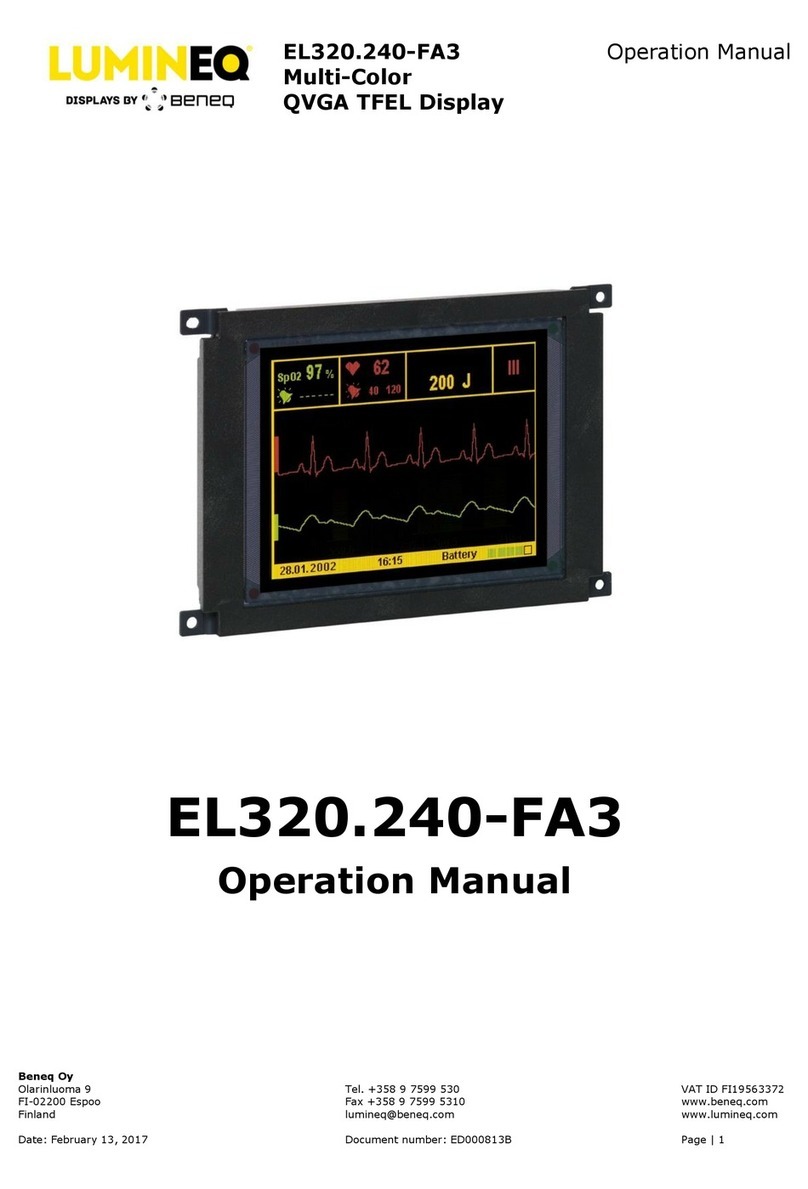
TOX EPW400 User manual

TOX®PRESSOTECHNIK GmbH & Co. KG Riedstraße 4 D-88250 Weingarten
Phone +49 (0) 751/5007-0 Fax +49 (0) 751/52391 www.tox-pressotechnik.com E-Mail: info@tox-de.com
Operating Manual
•
Force/Distance Measurement
Original operating manual
Firmware Version V1.08.88
Pressing monitor EPW400

Introduction
TOX®PRESSOTECHNIK GmbH & Co. KG Riedstraße 4 D-88250 Weingarten
Phone +49 (0) 751/5007-0 Fax +49 (0) 751/52391 www.tox-pressotechnik.com E-Mail: info@tox-de.com
This operating manual applies to devices running firmware version V1.08.81 or higher.


NOTICE OF COMPLETION
AND
INITIAL PRODUCTION INSPECTION
Page 1
2019-08-30
TOX-PRESSOTECHNIK L L C
MR. ERIC SEIFERTH
4250 Weaver Pkwy
Warrenville, IL, 60555-3924 USA
Our Reference: File E503298, Vol. D1 Project Number: 4788525144
Your Reference: Models EPW 400, Smart9 T070E, Smart9 T057, STE 341-xxx T070, STE346-0005, CEP
400T, Touch Screen PLC's
Project Scope: UL Listing to the following standard(s):
UL 61010-1, 3rd Edition, May 11, 2012, Revised April 29 2016, CAN/CSA-C22.2 No.
61010-1-12, 3rd Edition, Revision dated April 29 2016
Subject: Notice of Project Completion with Initial Production Inspection
Dear MR. ERIC SEIFERTH:
Congratulations! UL's investigation of your product(s) has been completed under the above Reference Numbers and
the product was determined to comply with the applicable requirements. The Test Report and records in the Follow-
Up Services Procedure covering the product are completed and are now being prepared (if you do not have a
separate CB Report, you can to access the Test Report now). Please have the appropriate person in your
company that is responsible for receiving/managing UL reports access an electronic copy of the Test Report
and FUS Procedure through the CDA feature on MyHome@UL, or if you desire another method of receiving
the report please contact one of the contacts below. If you are not familiar with our MyHome site or need to
create a new account in order to access your reports, please click the link HERE.
PLEASE NOTE: YOU ARE NOT AUTHORIZED TO SHIP ANY PRODUCTS BEARING ANY UL MARKS UNTIL
THE INITIAL PRODUCTION INSPECTION HAS BEEN SUCCESSFULLY CONDUCTED BY THE UL FIELD
REPRESENTATIVE.
An Initial Production Inspection (IPI) is an inspection that must be conducted prior to the first shipment of products
bearing the UL Mark. This is to ensure that products being manufactured are in accordance with UL LLC’s
requirements including the Follow-Up Service Procedure. After the UL Representative has verified compliance of your
product(s) at the manufacturing locations listed below, authorization will be granted for shipment of product(s) bearing
the appropriate UL Marks as denoted in the Procedure (located in the FUS Documentation of the report).
List of all manufacturing locations (please contact us if any are missing):
Manufacturing
Facility(ies):
TOX PRESSOTECHNIK GMBH & CO. KG
Riedstraße 4
88250 Weingarten Germany
Contact Name: EricSeiferth
Contact Phone No.: 1 630 447-4615
Contact Email: ESEIFERTH@TO
X
-US.COM
It is the responsibility of TOX-PRESSOTECHNIK L L C, the Applicant, to inform its manufacturers of that the IPI must
be successfully completed before product may be shipped with the UL Mark. Instructions for the IPI will be sent to
our inspection center nearest to each of your manufacturing locations. The contact information of the inspection
center is provided above. Please contact the inspection center to schedule the IPI and ask any questions you may
have regarding the IPI.
Inspections at your production facility will be conducted under the supervision of:
Area Manager: ROB GEUIJEN
IC Name: UL INSPECTION CENTER GERMANY,
Address: UL INTERNATIONAL GERMANY GMBH
ADMIRAL-ROSENDAHL-STRASSE 9, NEU-
ISENBURG, Germany, 63263
Contact Phone: 69-489810-0

Page 2
Email:
Marks (as needed) may be obtained from:
Information on the UL Marks, including our new Enhanced UL Certification Marks can be found on the UL website at
https://markshub.ul.com
Within Canada, there are federal and local statutes and regulations, such as the Consumer Packaging and Labeling
Act, requiring the use of bilingual product markings on products intended for the Canadian market. It is the
responsibility of the manufacturer (or distributor) to comply with this law. The UL Follow-Up Service Procedures will
only include the English versions of the markings
Any information and documentation provided to you involving UL Mark services are provided on behalf of UL LLC
(UL) or any authorized licensee of UL.
Feel free to contact me or any of our Customer Service representatives if you have any questions.
UL is strongly committed to providing you with the finest customer experience possible. You may receive an email
from [email protected].com inviting you to please participate in a brief satisfaction survey. Please check your
spam or junk folder to ensure receipt of the email. The subject line of the email is “Tell is about your recent
experience with UL.” Please direct any questions about the survey to [email protected]. Thank you in
advance for your participation.
Very truly yours,
Brett VanDoren
847-664-3931
Staff Enginee
r

Table of contents
6OM 100.EPW400.202002.en
Table of contents
1Introduction....................................................................................................11
1.1 Explanation of symbols...........................................................................11
2Brief description ............................................................................................12
2.1 Function of the pressing monitor.............................................................12
2.2 Measuring Mode and Configuration........................................................12
2.3 Version .22 .............................................................................................13
3Technical data................................................................................................14
3.1 General technical data............................................................................14
3.1.1 Power supply...............................................................................14
3.1.2 Hardware configuration................................................................14
3.1.3Connections.................................................................................15
3.1.4 Digital inputs................................................................................16
3.1.5 Digital outputs..............................................................................16
3.1.6 USB.............................................................................................17
3.1.7 Ethernet.......................................................................................18
3.1.8 Environmental conditions.............................................................18
3.1.9 Electromagnetic compatibility in line with EC directives................19
3.1.10 Sensor: analog standard signals..................................................20
3.1.11 Sensor: supply voltage.................................................................20
3.1.12 Screw sensor with standard signal output....................................20
3.1.13 DMS signals.................................................................................21
3.2 Overview of built-in version.....................................................................22
3.2.1 Mechanical specifications ............................................................22
3.2.2 Dimensions of installation housing with two slots.........................23
3.2.3 Dimensions of installation housing with three slots.......................23
3.2.4 Hole pattern of installation housing (rear view).............................24
3.2.5 Built-in version: digital inputs I0 – I15 (37-pin connector) .............25
3.2.6 Built-in version: digital outputs Q0 – Q7 (37-pin connector)..........26
3.2.7 Built-in version: pin assignment, DMS force transducer (channel
Y).................................................................................................27
3.2.8 Built-in version: pin assignment, analog signals (channel Y force /
channel X distance) for analog standard signals..........................28
3.2.9 Built-in version: pin assignment, analog standard signals ............30
3.3 Overview of wall-mounted version ..........................................................32
3.3.1 Power supply...............................................................................32
3.3.2 Dimensions of wall-mounted version............................................32

OM 100.EPW 400.202002.en 7
3.3.3 Wall-mounted housing: digital inputs I0-I15 (25-pin D-sub female
connector)....................................................................................33
3.3.4 Wall-mounted housing: digital outputs Q0-Q7 (25-pin D-sub female
connector)....................................................................................33
3.3.5 Standard wall-mounted housing: pin assignment, DMS force
transducer (channel Y).................................................................34
3.3.6 Wall-mounted housing: pin assignment, force transducer (channel
Y) Only hardware model EPW 400.202.1X ................................38
3.4 Interfaces................................................................................................40
3.4.1 Profibus .......................................................................................40
3.4.2 Fieldbus interface ........................................................................42
4Transport........................................................................................................45
4.1 Storage...................................................................................................45
4.2 Transport................................................................................................45
4.3 Dispatch for repair ..................................................................................45
5Operating the device .....................................................................................46
5.1 Switching on the EPW 400 .....................................................................46
5.2 Operating the device via touch screen (touch-sensitive screen).............46
5.3 Main menu 'Measuring'...........................................................................47
5.3.1 Buttons (from left to right) ............................................................47
5.3.2 Icons............................................................................................48
5.3.3 Full screen display:......................................................................49
5.4 Menu 'Zoom'...........................................................................................50
5.4.1 Buttons (from left to right) ............................................................50
5.5 Menu 'Gauge curve'................................................................................53
5.5.1 Buttons ........................................................................................53
5.6 Menu 'Windows'......................................................................................54
5.6.1 Edit window type..........................................................................55
5.7 Menu 'Envelope curve'............................................................................61
5.7.1 Text fields....................................................................................63
6Configuring the EPW 400..............................................................................65
6.1 Processes...............................................................................................65
6.1.1 Select process number (64 processes)........................................66
6.1.2 Assign process name (max. 40 characters).................................66
6.1.3 Copy processes...........................................................................67
6.1.4 Settings........................................................................................68
6.1.5 Saving / restoring parameters......................................................69
6.2 Configuration..........................................................................................70

Table of contents
8OM 100.EPW400.202002.en
6.2.1 Force sensor, channel Y..............................................................71
6.2.2 Nominal force of the force sensor (Nominal load) Version 22.......71
6.2.3 Nominal force of the force sensor (Nominal load).........................72
6.2.4 Offset force sensor.......................................................................72
6.2.5 Force sensor offset adjustment....................................................72
6.2.6 Offset limit force sensor ...............................................................73
6.2.7 Forced offset force sensor ...........................................................73
6.2.8 Source force sensor.....................................................................73
6.2.9 Nominal characteristic value of force sensor................................73
6.2.10 Filter.............................................................................................73
6.2.11 Force sensor calibration...............................................................74
6.2.12 Force 1 ........................................................................................74
6.2.13 Force 2 ........................................................................................75
6.2.14 Distance sensor...........................................................................76
6.2.15 Distance sensor Version 22 .........................................................76
6.2.16 Nominal distance of the distance sensor (nominal load)...............77
6.2.17 Distance sensor offset..................................................................77
6.2.18 Offset adjustment of distance sensor...........................................77
6.2.19 Offset limit of distance sensor......................................................78
6.2.20 Forced offset of distance sensor..................................................78
6.2.21 Filter.............................................................................................78
6.2.22 Distance sensor calibration..........................................................79
6.2.23 Measuring parameters.................................................................81
6.2.24 Measured data acquisition (measuring parameters).....................81
6.2.25 Distance rising .............................................................................82
6.2.26 Distance rising or falling...............................................................82
6.2.27 Force or distance change.............................................................82
6.2.28 Time-triggered .............................................................................82
6.2.29 Insert max. force at the end of the curve......................................83
6.2.30 Start/stop condition......................................................................83
6.2.31 Distance-triggered........................................................................83
6.2.32 Force-triggered ............................................................................84
6.2.33 Start/stop from PLC .....................................................................84
6.2.34 Switching points...........................................................................84
6.2.35 Configuration I/O..........................................................................85
6.2.36 Configuring the analog outputs ....................................................87

OM 100.EPW 400.202002.en 9
6.2.37 Valuation options .........................................................................88
6.2.38 Activate NOK buzzer (NOK buzzer).............................................88
6.2.39 NOK acknowledge external (reset) ..............................................88
6.2.40 NOK acknowledge via display (reset) ..........................................88
6.2.41 Monitor TDC sensor.....................................................................88
6.2.42 Apply configuration ......................................................................89
6.3 Data........................................................................................................90
6.3.1 Curve data...................................................................................90
6.3.2 Final values .................................................................................91
6.3.3 Settings........................................................................................92
6.3.4 Settings for data export to PC......................................................93
6.4 Lot size...................................................................................................94
6.4.1 Job counter..................................................................................94
6.4.2 Shift counter ................................................................................95
6.4.3 Tool counter.................................................................................96
6.5 Diagram settings.....................................................................................97
6.6 Supplemnt ..............................................................................................98
6.6.1 User administration......................................................................99
6.6.2 Language...................................................................................102
6.6.3 Communication parameters....................................................... 102
6.6.4 IP address .................................................................................103
6.6.5 Remote access..........................................................................103
6.6.6 In-/Outputs.................................................................................104
6.6.7 Internal digital I/O.......................................................................105
6.6.8 Field bus parameters.................................................................106
6.6.9 Profibus address (only for Profibus version)............................... 106
6.6.10 Read inputs to Anybus-S module............................................... 107
6.6.11 Log final values on field bus.......................................................107
6.6.12 Write actual values.....................................................................107
6.6.13 Read DMC code........................................................................107
6.6.14 Number of IO bytes....................................................................107
6.6.15 Profibus / Anybus.......................................................................108
6.6.16 Analog inputs.............................................................................109
6.6.17 Date/Time..................................................................................110
6.6.18 Device name..............................................................................111
7PLC interface pulse diagrams..................................................................... 112

Table of contents
10 OM 100.EPW400.202002.en
7.1 Start/Stop..............................................................................................112
7.1.1 Changing the program number ..................................................113
7.1.2 Zero point adjustment ................................................................113
8Software module TOX®softWare.................................................................114
8.1 Networking via Ethernet........................................................................114
8.2 Network server program EPW 400_Server...........................................114
9Error messages............................................................................................115
10 Firmware update..........................................................................................116
10.1 Update from version V1.08 ...................................................................116
11 Decommissioning........................................................................................118
11.1 Storage.................................................................................................118
11.2 Disposal................................................................................................118

Introduction
OM 100.EPW 400.202002.en 11
1 Introduction
1.1 Explanation of symbols
An arrow at the beginning of a paragraph indicates the action steps you must
complete.
This tick at the beginning of a paragraph indicates a condition that must be met
before beginning the next step.
Danger notifications:
Safety
Here you will find instructions for the prevention of damage.
These safety notes must be strictly observed by the operating com-
pany and user of the machine.
Operating notes:
Note
Provides information on work sequences and methods that facilitate
the use of the machine.
Setting
Indicates important information about setting the operating parame-
ters.
Function
Explains the functioning of the machine or the sequence of a work-
ing process.

Brief description
12 OM 100.EPW400.202002.en
2 Brief description
The pressing monitor EPW ensures constant monitoring and cares for quality assur-
ance during production.
2.1 Function of the pressing monitor
The Pressing Monitor EPW 400 monitors processes in which precisely defined func-
tional correlations between force and distance have to be verified. For this purpose,
the device reads the force/distance data pairs from two measuring channels 'X' and
'Y' during the measuring operation. The data are written to memory and can be dis-
played graphically. The resulting force/distance function is compared with the speci-
fied data limits of the set window values or envelope curve. An OK message is issued
if the data limits are complied with, otherwise a NOK message is issued.
2.2 Measuring Mode and Configuration
The device has two operating modes: "measuring" and "configuration". Only during
measuring mode can a registration followed by an evaluation be started. If the settings
on the EPW 400 are changed, e.g. during a program change or zero point adjustment,
or if the settings are being changed via the keyboard, it is not possible to begin a
measuring cycle.
The readiness for measuring is shown on the display by means of ready
signal 'RDY'.

Brief description
OM 100.EPW 400.202002.en 13
2.3 Version .22
Principle display of the Pressing Monitor EPW400 as Version 22, with changeover
from channel pair A to channel pair B.
You have the option of setting channels A and B for each process independent of
force and distance.
Note
Only the one channel pair (A or B) can be used to measure and not
both simultaneously!

Technical data
14 OM 100.EPW400.202002.en
3 Technical data
3.1 General technical data
3.1.1 Power supply
Input voltage:
24 V / DC, ± 25% (incl. 10% residual ripple)
Current consumption:
≤ 1 A
3.1.2 Hardware configuration
CPU
ARM9 processor, frequency 200 MHz, passively
cooled
Memory storage
1 x 256 MB CompactFlash (can be expanded to 4
GB)
2 MB boot flash
64 MB SDRAM (firmware and parameters)
Data storage
1024 kB RAM, remanent, buffer battery for final
values and counter readings
Real-time clock / accuracy
At 25°C ≤ ± -1 s / day,
at 10 to +70C°: ≤ + 1 s to 11 s / day
Display
TFT, backlit, 5.7" graphics-capable
TFT LCD VGA (640 x 480)
Color depth: 16-bit
Backlit LED, switchable via software
Contrast 300:1
Brightness: 220 cd/m2
Viewing angle vertical 100°, horizontal 140°
Analog resistive, color depth 16-bit
Interface extensibility
1 x slot for back plane
1 x keyboard interface for max. 64 buttons with
LED
Buffer battery
Lithium cell, pluggable
Battery type Li 3 V / 950 mAh CR2477N
Buffer time at 20°C typically 5 years
Battery monitoring typically 2.65 V
Buffer time for battery change min. 10 minutes
Order number: 300215

Technical data
OM 100.EPW 400.202002.en 15
Battery change
Recommendation: change battery after 2 years.
To avoid data loss while performing the battery change, turn the de-
vice on for at least 10 minutes before the change-over.
1 Disconnect the power supply
2 Discharge any electrostatic charges
3 Remove the cover from the lithium battery
4 Remove the battery. (Do not use uninsulated tools - risk of
short circuiting)
5 Insert new battery with correct polarity
6 Replace the battery cover
3.1.3 Connections
•16 digital inputs
•1 USB device
•8 digital outputs
•1 CF memory card
•1 Ethernet interface
Correct: Incorrect:

Technical data
16 OM 100.EPW400.202002.en
3.1.4 Digital inputs
16 digital inputs
Isolated
Input voltage
24 V (permissible range: -30 V to +30 V)
Input current
At rated voltage (24 V): 6.1 mA
Delay time of standard inputs
tLOW-HIGH 3.5 ms
tHIGH-LOW 2.8 ms
Input voltage
LOW level: ≤ 5 V
HIGH level: ≥ 15 V
Input current
LOW level: ≤ 1.5 mA
HIGH level: ≥ 3 mA
Input impedance 3.9 kΩ
3.1.5 Digital outputs
8 digital outputs
Isolated
Load voltage Vin
Rated voltage 24 V
(permissible range 18 V to 30 V)
Output voltage
HIGH level min. Vin-0.64 V
LOW level max. 100 µA • RL
Output current
max. 500 mA
Parallel connection of outputs possible
Max. 4 outputs with Itot = 2 A
Short-circuit proof
Yes, thermal overload protection
Switching frequency
Resistive load 100 Hz
Inductive load 2 Hz (dependent
on inductance)
Lamp load max. 6 W
Simultaneity factor 100%
Avoid reversing current
Reversing current at the outputs may damage the output drivers.
On devices with field bus interface, the outputs, such as "Ready for operation", are
written on both the digital outputs and the field bus outputs. Whether the inputs are
read on the digital inputs or on the field bus inputs is determined in menu 'Additional-
>Communication parameters->Anybus-S Subprint'.

Technical data
OM 100.EPW 400.202002.en 17
3.1.6 USB
Number of
channels
2 x host (full-speed)
1 x device (high-speed)
USB 2.0
According to USB device specification,
USB 2.0 compatible, type A and B
Connection to high-powered hub/host
Max. cable length 5 m
Pin MIO
1
+ 5 V
2 Data -
3 Data +
4 GND
Note
With the wall-mounted version of the EPW 400, it is not possible to
access all the USB interfaces from the outside.

Technical data
18 OM 100.EPW400.202002.en
3.1.7 Ethernet
1 channel
Twisted pair (10/100BASE-T),
Transmission according to IEEE/ANSI 802.3, ISO 8802-3,
IEEE 802.3u
Transmission
speed
10/100 Mbit/s
Connecting line
Shielded,
at 0.14 mm²
Max. 300 mm
At 0.25 mm²:
max. 600 mm
Length
max. 100 mm
Cable
Shielded, impedance 100 Ω
Connector
RJ45 (modular connector)
LED status indica-
tor
Yellow: transmis-
sion
Green: ready
3.1.8 Environmental conditions
Temperature
Operation
0 to +45°C
Storage
-25 to +70°C
Relative humidity without condensation (acc. to RH2) 5 to 90%
Vibrations according to
IEC 68-2-6
15 to 57 Hz,
Amplitude 0.0375 mm,
occasionally 0.075 mm
57 to 150 Hz,
Acceleration 0.5 g
occasionally 1.0 g

Technical data
OM 100.EPW 400.202002.en 19
3.1.9 Electromagnetic compatibility in line with EC directives
Immunity according to EN 61000-6-2 / EN 61131-2
Electrostatic discharge (EN 61000-4-2)
Contact
min. 8 kV
Clearance
min. 15 kV
Electromagnetic fields (EN 61000-4-3)
80 MHz – 1 GHz:
10 V/m 80% AM
(1 kHz)
900 MHz ±5 MHz:
10 V/m 50% ED
(200 Hz)
Fast transients (EN 61000-4-4)
Power supply lines
2 kV
Process digital In-output
1 kV
Process analog inputs out-
puts
0.25 kV
Communication interfaces
0.25 kV
Induced high frequency (EN 61000-4-6)
0.15 – 80 MHz
10 V 80% AM (1 kHz)
Surge voltage 1.2/50: min. 0.5 kV (measured at AC/DC converter input)
Emission interference according to EN61000-6-4 / EN61000-4-5
RFI voltage EN 55011
150 kHz – 30
MHz
(Group 1,
Class A)
RFI emissions EN 50011
30 MHz – 1 GHz
(Group 1,
Class A)
Compliance with the EC Directive
Compliance with EMC directives requires correct installation in ac-
cordance with the device manual.
The person marketing the complete machine is responsible for the
electromagnetic compatibility of the overall system into which the
control system is integrated.

Technical data
20 OM 100.EPW400.202002.en
3.1.10 Sensor: analog standard signals
Measuring is carried out by a sensor with a standardized process signal 0-10 V. The
input is selected in menu 'Configuration'.
Nominal force or nomi-
nal distance:
Adjustable via the menu
A/D converter:
12 bit = 4096 steps (for EPW 400.x02.1x)
16 bit = 65536 steps (for EPW 400.x02.0x)
Nominal load of reso-
lution:
Steps see A/D converter, 1 step (bit) = nominal load /
steps
Accuracy of measure-
ment:
1%
Max. sampling rate:
2000 Hz (0.5 ms)
3.1.11 Sensor: supply voltage
Auxiliary voltage:
24 V ± 5%, max. 100 mA
Reference voltage:
10 V ± 1% nominal signal: 0 – 10 V
Adjustment value
The entries 'Nominal force' or 'Nominal distance' must not be
changed without the agreement of the manufacturer.
3.1.12 Screw sensor with standard signal output
Auxiliary voltage:
24 V ± 5%, max. 100 mA
Nominal signal:
0 – 10 V
Tare signal:
0 V = zero adjustment, > 9 V = measuring mode
Adjustment value
The entry 'Nominal force' must not be changed without the agree-
ment of the manufacturer.
Tightening torque: 14 Nm
Zero adjustment before each work cycle
With some types of force transducers or measurement amplifiers
with tare function, a decrease of the measuring accuracy is possible
after a certain period of time depending on the process. In order to
ensure repeating accuracy, a zero adjustment should be carried out
before each work cycle or at regular time intervals (e.g. for ZKN
model force transducers after approx. 10 minutes).
Table of contents
