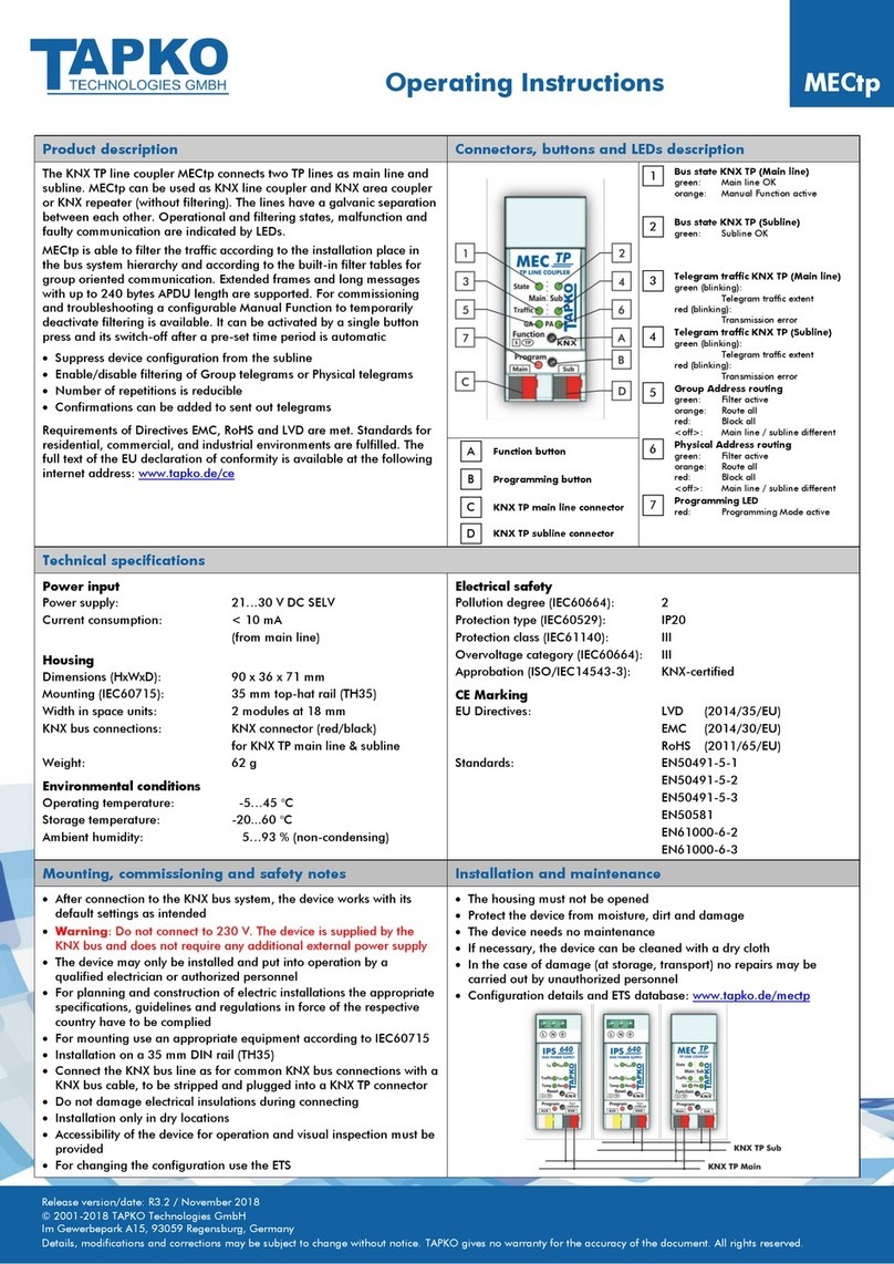
Toyo SOT-MQ82 Series User manual

DS4-2731C
- 1 -
CC-Link Space Optical Repeater
SOT-MQ82/162 series
Operation Manual
TOYO ELECTRIC CORPORATION

DS4-2731C
- 2 -
TABLE OF CONTENTS
1. Introduction 3
2. Outline 3
3. Construction 3
3-1. Model number 3
3-2. Combination 3
4. Major specifications 4
5. Constituent parts and their functions 5
6. Data linking procedure 6
6-1. Procedure 6
6-2. Setting the switches 7
6-3. Installation 8
6-4. Electric connections 11
6-5. Beam path adjustment 14
6-6. Monitoring function 14
7. External output circuit 16
8. Inspection and maintenance 17
9. Caution in use 17
10. External dimensions 18
11. Warranty 19
12. Contact 19
13. Revision history 20

DS4-2731C
- 3 -
1. Introduction
Thank you for choosing our SOT-MQ82/162 series, CC-Link space optical repeater.
To ensure the correct use, please thoroughly read this manual before use.
2. Outline
The SOT-MQ82/162 is a high-speed space optical transmitter using infrared rays.
(1) It optically transmits CC-Link data.
The CC-Link cable can be replaced with space optical communication.
(2) The optical reception status can be communicated to the master station and used for
maintenance or another purpose.
(3) The data transfer rates of 156 kbps, 625 kbps, 2.5 Mbps are supported.
(4) Dip switch allows to switch the channel to the one having different carrier frequency and to
communicate with up to two opposite directions in series or parallel without interference.
3. Construction
3.1 Model number
SOT - MQ 16 2
Optional specification No code: No specification
CH1 CH2
Carrier wave frequency A: 14.5MHz 21.5MHz
B: 18.0MHz 25.0MHz
Transmission distance 16: 0.2 to 160m
8: 0.2 to 80m
Series name MQ: 2.5Mbps CC-Link
3-2. Combination
(1) Use a type A carrier wave unit and a type B one as a pair.
A pair consisting of two type A units or two type B units does not work.
(2) The SOT-MQ82/162 series are not compatible with other space optical transmission
units.
Type A Type B
Power supply
Auxiliary outputs
CC-Link
Auxiliary outputs
Power supply
CC-Link

DS4-2731C
- 4 -
4. Major specifications
Item Specifications
Model SOT-MQ162A/B SOT-MQ82A/B
Operating environment CC-Link Ver.1.10/Ver.2.00
Data transfer rate 156k, 625k, 2.5Mbps
Supply voltage Rated voltage: 24VDC, 10% or less ripples
Operating voltage: 18-30VDC, 30V or less at peak including ripples
Current consumption Less than 150mA
Interface RS485 compliant
Transmission mode Semi-duplex, bi-directional
Communication control
mode
Bit forward
# of occupied stations When using the monitoring function: 1
When not using the monitoring function: 0
Transmission distance 0.2-160m 0.2-80m
Detection angle 1° (horizontal and vertical) 1° (horizontal and vertical)
Modulation mode FSK
Projector element Near infrared light emitting diode (870nm in wavelength)
Receiver element Photo diode
Auxiliary outputs CDO: On when data is received.
ALM: Off when the reception level is low.
A photo-coupler insulated, NPN open collector output
Rated output level: 30VDC, 50mA max.
Electric connections For CC-Link signals: 4-pin connector terminal block
(PHOENIX MSTB 2,5/4-GF-5,08)
For power supply and auxiliary outputs:5-pin connector terminal block
(PHONEIX MSTB 2,5/5-GF-5,08)
Check terminals Applies an output DC voltage corresponding to the reception level.
(Use the DC voltage range of a 10kΩ/V or higher tester.)
Operating ambient
illumination
Sunlight : 10,000 lx or less
Fluorescent or candescent lamps : 3,000 lx or less
No ambient light shall directly enter the receiver.
Operating ambient
temperature
-10-55°C No frozen parts allowed.
Operating ambient
humidity
10-85% RH No condensation allowed.
External dimensions
(weight)
See “External dimensions” (approx. 350g).
Accessories A set of fittings, mounting screws (4),
signal plug (1), power/auxiliary output plug (1),
110Ωterminal resistors (2) and 130Ωterminal resistors (2)

DS4-2731C
- 5 -
5. Constituent parts and their functions
(1) Power indicator (POW): Shows red when the power supply in on.
(2) Clear data indicator (↓CD): Shows red when the reception level at the station
is sufficient for communication.
(3) Reception level indicator (↓1 to 4): Shows green to indicate the reception level at the
station.
(4) Monitor running indicator (LRUN): Shows green during normal communication using
the monitoring function.
Remains off when the monitoring function is not
used.
(5) Monitor error indicator (LERR): Shows red during faulty communication using the
monitoring function.
Remains off during normal communication using
the monitoring function or when the monitoring
function is not used.
(6) Communication error indicator (ERR): Shows red during faulty CC-Link communication.
(7) Sent data to cable indicator (SD1): Shows red when data is transmitted to the cable.
(8) Sent data to optical unit indicator (SD2): Shows red when data is transmitted to the optical
unit.
(9) Received data from cable indicator (RD1): Shows green when data is received from the cable.
(10) Received from optical unit indicator (RD2): Shows green when data is received from the
optical unit.
(11) Channel indicator (CH) Remains off when choosing CH1.
Shows red when choosing CH2.
(12) Opposite station data clear indicator (↑CD): Shows red when the monitoring function is used
and the reception level at the opposite station is
sufficient for communication.
(13) Opposite station reception level indicator (↑1 to 4): Shows green to indicate the reception level at the
opposite station when the monitoring function is
used.
(14) + check terminal (red): Applies an output DC voltage corresponding to the
reception level. (Use the DC voltage range of a
10kΩ/V or higher tester).
(15) – check terminal (black)
(16) Setting switches: Used to select the data transfer rate and to switch
carrier frequency.
(17) Station number setting switches: Used to select the data transfer rate and carrier
frequency.
(18) Power/auxiliary output plug: FKCT 2.5/5-STF-5.08, Phoenix Contact
(19) Signal plug: FKC 2.5/4-STF-5.08, Phoenix Contact
(20) FG terminal: For connecting external FG, M3 threaded
1
2
8 7
3
4 613 12
10 9 5
11
19
14
15
17
18
16
20

DS4-2731C
- 6 -
6. Data linking procedure
6-1. Procedure
Start
↓
Setting the switches
Set to the SOT station number and data
transfer rate.
See subsection 6-2.
↓
Installation
Install the SOT units on the equipment. See subsection 6-3.
↓
Wiring the cables
Wire the power and dedicated CC-Link cables. See subsection 6-4.
↓
Beam path adjustment
Adjust the beam path while checking the CD
and level indicators on each SOT unit. See subsection 6-5.
↓
Setting the master unit
Set up the master unit.
↓
Circuit check
Check the CC-Link circuit.
↓
Creating a monitoring program
Create a PLC program to control the
monitoring function.
See subsection 6-6.
↓
End
is the step recommended to see the User’s Manuals for the CC-Link master and local units.

DS4-2731C
- 7 -
6-2. Setting the switches
6-2-1. Setting switches
(1) Detail of settings
Detail of settings
SW1 Used to select the data transfer
rate
SW2
SW3 Not used (used when off)
SW4 Used to switch channels
(2) Data transfer rate selection (SW1, 2)
SW1 SW2 Data transfer rate
OFF OFF 156k
ON OFF
625k
OFF ON 2.5M
ON ON Not valid
The switches have been factory-set to “156 kbps.”
(3)Channel select switch (SW4)
SW4 Carrier frequency
OFF CH1 selected
ON CH2 selected
The switches have been factory-set to “CH1 selected.”
6-2-2. Station number setting switches
(1) Detail of settings
(2)
Detail of settings
×10 ×1
x10: Set to the first-digit value of the
station number.
X1: Set to the second-digit value of the
station number.
Set to 00 when using the monitoring
function.
01 to 64: Specifies the station number
when using the monitoring function.
65 to 99: Not valid
The switches have been factory-set to “00.”
(2) When using the monitoring function, set the station number to “01” if there is no preceding
station.
If there is any preceding station, set to the “preceding station number + the number of
stations occupied by the preceding station unit.”
Example: If the previous station number is “01” and two stations are occupied by the unit,
the current station number will be “03.”
0
9
8
7
6
5
4
3
2
1
0
9
8
7
6
5
4
3
2
1

DS4-2731C
- 8 -
6-3. Installation
6-3-1. Drilling dimensions for mounting holes
6-3-2. Caution about the place for installation
In order not to spoil the transmitter performance, the transmitter shall not be installed in a place
where:
(1) it may be directly exposed to splashes of water, oil, dust and/or chemical,
(2) optical signals may be dampened by aqueous vapor, smoke, corrosive gas or the like (the
projector and receiver ports are made of resin and shall not be cleaned with paint thinner
based solvent),
(3) the transmitter may be exposed to temperatures, humidity, vibration and/or impact
exceeding the ratings (the transmitter shall be protected when it is continuously exposed to
vibration or impact even not exceeding the rating),
(4) a device generating a strong magnetic field, e.g. magnet or motor, or a device or power
wire generating strong noises, e.g. inverter, is used nearby,
(5) the sunlight or incandescent light containing strong infrared rays directly enters the receiver
within 10 degrees from the center of the beam path (the transmitter shall be used indoors),
(6) the beam path between the receiver and projector may be interrupted by a passing person
or obstacle or optical signals may be dampened by aqueous vapor or smoke
(communication may be suspended when the beam path is interrupted)
(7) a reflective object or beams coming from another photoelectric switch that may optically
interfere with the transmitter is located above the beam path, or
(8) the beam path to a moving unit, if used, will be inclined by 1 degree or more when the
moving unit is making a zigzag, vibrating or given an impact.
Beam
direction
M4 screw mounting hole

DS4-2731C
- 9 -
6-3-3. Intervals between adjacent pairs
When installing two or more pairs of SOT units or using a one near another photoelectric
sensor, reserve a sufficient space between them to prevent optical interferences.
Example 1
*1. This setup does not interfere with data transfer but will affect the reception level
indicated on each unit. (When adjusting the beam path or checking the
reception level, turn off the other pair of units.)
Example 2
*2. This setup does not cause interferences unless disturbed by any reflective object.
Example 3
*3. Same condition is applicable as Example 1 when the channel is different.
Caution
Note that the severity of optical interferences depends on the beam path adjustment and
misalignment factors such as vibration or impact. When installing a unit on a moving cart
or the like, adjust the beam path according to 6-5 “Beam path adjustment” and check the
performance before use to ensure normal communication throughout the whole
communication area.
Type A
Type B
Type B
Type A
0.5m or
more
Type AType B
Type BType A
*2
Type AType B
3m or more
*3
Type AType B

DS4-2731C
- 10 -
6-3-4. Installing directions
Install the SOT units in the opposite directions as shown in (1) below.
They do not work if rotated as shown in (2) or (3).

DS4-2731C
- 11 -
6-4. Electric connections
6-4-1. Power/auxiliary output connector
Signal name Code Terminal
number
24V 1
Power supply GND 2
CDO 4
ALM 5
Auxiliary
outputs COM 3
Arrangement of cable connecting terminals
(1) Applicable connector (enclosed)
Plug, FKCT 2.5/5-STF-5.08 (1902330), Phoenix Contact or equivalent
(2) Recommended cable
Use a 0.3mm2or thicker cable for power supply and auxiliary outputs.
(Check the voltage drop across the cable and use it within a length not exceeding 50m.)
6-4-2. Signal connector
Signal name Code Terminal
number
Signal A DA 1
Signal B DB 2
Signal ground DG 3
Shielded SLD 4
Arrangement of cable connecting terminals
(1) Applicable connector (enclosed)
Plug, FKC 2.5/4-STF-5.08 (1873223), Phoenix Contact or equivalent
(2) Recommended cable
Use a dedicated CC-Link cable.
The CC-Link system performance cannot be guaranteed if used with a cable other than
dedicated for CC-Link.
For specifications and other details of the dedicated CC-Link cable, see:
CC-Link Partner Association’s homepage: http://www.cc-link.org/

DS4-2731C
- 12 -
6-4-3. Connecting the dedicated CC-Link cables
(1) Use dedicated CC-Link cables of the same type in each segment. Using different types of
cables together does not guarantee normal data transfer.
(2) The intervals required between adjacent dedicated CC-Link cables and the maximum
extension length depend on the data transfer rate and the construction of the equipment
used. For detail, see the User’s Manual for the master unit.
(3) For the units at either ends of each segment, always connect the terminal resistor between
DA and DB. The SOT units themselves contain no terminal resistor.
Use compatible ones of the attached terminal resistors (110Ωand 130Ω) with the cable.
DA
DB
DG
SLD
FG
DA
DB
DG
SLD
FG
DA
DB
DG
SLD
FG
DA
DB
DG
SLD
FG
DA
DB
DG
SLD
FG
Dedicated CC-Link
cable
Master unit
SOT-MQ82/162
Remote unit
SOT-MQ82/162
Remote unit
Terminal
resisto
r
Terminal
resistor
Terminal
resistor
Terminal
resistor
Dedicated CC-Link
cable
Dedicated CC-Link
cable
Space optical
transmission

DS4-2731C
- 13 -
6-4-4. Measures to be taken to comply with the EMC Directive
The measures to be taken to ensure conformity of this optical transmission device with the EMC
Directive are described below.
To ensure conformity of the entire CC-Link system with the EMC Directive, it is necessary to take
all the necessary measures for the peripheral devices, such as the slave unit and power supply,
referring to the appropriate hardware manuals for the sequencer CPU.
(1) Attaching a ferrite core to the CC-Link cable
Attach a ferrite core to the CC-Link cable in the vicinity of the optical transmission device.
This ferrite core must have attenuation characteristics equivalent to those of the TDK
ZCAT3035-1330 ferrite core.
Please note that the measures described above are deemed as the best method based on the
information on the regulatory requirements and standards that is currently available to us.
However, use of the entire system incorporating this optical transmission device after completion
of these measures does not always ensure conformance to the EMC Directive.
It is the responsibility of the system manufacturer to specify the method for ensuring conformity
of the entire system with the EMC Directive and make a final decision on its compliance.
Ferrite core

DS4-2731C
- 14 -
6-5. Beam path adjustment
A data link error occurs during beam path adjustment.
Before starting, remove the cable from the connector or check that no trouble will be caused if a
data link error occurs.
(1) After ensuring correct wiring, turn on the SOT units.
The power indicator (POW) on each unit shows red.
(2) Loosen the unit and fitting mounting screws and move the unit in every direction until the
clear data indicator (CD) on the opposite unit shows red.
Note: The opposite station reception level indicator on the unit only lights when the
monitoring function is used and the reception level at the station is CD or higher.
First, adjust while checking the reception level indicated on the opposite unit.
(3) Finely adjust until the reception level indicator on the opposite unit shows green at level 3 or
higher. The accurate reception level can be measured with a tester connected to the check
terminals on the opposite unit.
Use the DC voltage range of a tester with an input resistance of 10kΩ/V around 10V.
Insert φ2 tester probes into the (+) and (-) check terminals.
(4) The maximum voltage at the check terminals shall be 4.2V.
As a guide, the voltage shall be 2.2V or higher at the maximum transmission distance and
fixed nearly around the maximum level.
(5) Adjust the opposite unit in the same manner.
(6) When installing a unit on a moving object such as stacker crane, check that the reception
level indicators on both the moving and fixed units show green at level 3 or higher
throughout the entire region of motion.
(7) The communication error indicator (ERR) shows red when disturbed by reflected or ambient
light. When installing a unit on a moving object such as stacker crane, check that the
communication error indicators on both the fixed and moving units will not show or blink red
throughout the entire region of motion.
6-6. Monitoring function
The monitoring function communicates the reception status of each SOT unit to the master
station.
When using the monitoring function, it is necessary to specify the station number and set
parameters as remote I/O station.
6-6-1.Master unit input/output signals
(1) Input signals (SOT-MQ to master unit)
Device No. Signal name Description
RXn0 Local CD Input station’s CD signal
RXn1 Local ALM Input station’s ALM signal
RXn2 LocalL1 Input station’s L1 signal
RXn3 LocalL2 Input station’s L2 signal
RXn4-RX(n+1) Reserve Reserved
* The reserved signals cannot be used.
(2) Output signals (master unit to SOT-MQ)
Device No. Signal name Description
RYn0-RYnF Reserve Reserved
RY(n+1)0 Remote CD
Opposite station’s CD signal
RY(n+1)1 Remote ALM
Opposite station’s ALM
signal
RY(n+1)2 RemoteL1
Opposite station’s L1 signal
RY(n+1)3 RemoteL2
Opposite station’s L2 signal
RY(n+1)4-RY(n+1)F Reserve Reserved

DS4-2731C
- 15 -
* The reserved signals cannot be used.
6-6-2. Correspondence between input/output signals and indicators
The correspondence between the input/output signal on/off statuses and the indicator
statuses is shown below:
Signal Indicator
LEVEL
CD ALM L1 L2 CD 1 2 3 4
OFF OFF OFF OFF × × × × ×
ON OFF OFF OFF
{× × × ×
ON ON OFF OFF
{{× × ×
ON ON ON OFF
{{{× ×
ON ON OFF ON {{{{×
ON ON ON ON {{{{{
6-6-3. Example of program
(1) Example of system construction
In this example, the QCPU, QJ61BT11N and SOT-MS are set up as shown below for explanation.
1. Insert the QJ61BT11N into slot 0.
2. Set the station number of SOT-MS162A
to “1” and that of SOT-MS162B to “2.”
3. Program the automatic refreshing.
RX refreshing device: X1000
RY refreshing device: Y1000
4. Set parameters
Station type: Remote I/O
# of occupied stations: 1
* For detail of parameter settings, see
the User’s Manual for the master unit.
(2) Monitoring program
With this monitoring program, the reception level at the opposite station can be determined with
the indicator and used for fine adjustment and maintenance.
× : Off
{: On
Slot 0
Power unit
162A, station
number “1”
162B, station
number “2”
Send reception level at
station 1 to station 2
Send reception level at
station 2 to station 1
Reception level at station 1
decreased when M0 is off
Reception level at station 2
decreased when M1 is off

DS4-2731C
- 16 -
7.External output circuit
( 1 ) DA
( 2 ) DB
( 3 ) DG
( 4 ) SLD
( 4 )
Terminal No. Abbrev.
CDO
( 5 ) ALM
( 2 ) GND
FG
( 1 ) 24V
( 3 ) COM
Signal connector
Power/auxiliary output connector
Terminal No. Abbrev.

DS4-2731C
- 17 -
8. Inspection and maintenance
(1) Periodically check the front cover for contamination.
The product optically transmits data and may malfunction if the front cover is
contaminated. If it is heavily contaminated, wipe it clean with a dry cloth or the like.
The projector and receiver ports are made of resin and must not be cleaned with toluene
based solvent.
(2) Check for loose or chattering mounting screws and tighten, if any.
9. Caution in use
(1) Caution about voltage ripples
Use a power supply that meets power specifications for the product.
When supplying from the power unit of a PLC (sequencer), check that the product will
normally function.
(2) Caution about the power reset
Data cannot be transmitted for about two seconds after power-up.
(3) Beam path adjustment
When installing the SOT units, never fail to adjust the beam path.
Data can be transmitted when the clear data indicator (CD) lights and the clear data
output signal (CDO) is on.
When the reception level indicator (level 1) does not light, the low reception level output
(ALM) signal is issued (off).
(4) Power wiring
The power cable length shall not exceed 50m.
Electric noises in various forms are induced into the power cable from electric
appliances on the power circuit and power cables coming from other equipment. They
may cause the units to malfunction even if the power cable is shorter than 50m.
In case the power cable wiring circuit has such disturbing factors:
(1) install the power unit nearby,
(2) shorten or separately wire the power cable, or
(3) use a cable shielded from electromagnetic fields.

DS4-2731C
- 18 -
10. External dimensions
As removed from bracket
5 x 12
oblong hole
Receiver
port
Projector
port
5 x 12
oblong hole

DS4-2731C
- 19 -
11. Warranty
(1) Warranty period
A year after delivery to the specified location.
(2) Scope of Warranty
If the product is found to have a fault attributable to us within the Warranty period
specified above, the faulty part will be replaced or repaired at our cost. This does not
apply to the faults resulting from:
(1) incorrect handling or abuse by the user,
(2) causes not related with the product,
(3) alternation or repair made by a party other than us, or
(4) natural disasters and accidents beyond our control.
Note that the Warranty only applies to the product itself and does not cover secondary
damages arising from a failure of the product.
12. Contact
For detail of the product, please contact the nearest sales office or the Kagiya Factory.
TOYO ELECTRIC CORPORATION
Kagiya Factory
Head office
/Kagiya Factory
1-39 Aza-hikizawa, Kagiya-cho, Kasugai City, Aichi Prefecture, 480-0393
Tel <0568>88-1181 (Rep.) Fax <0568>88-3086
Tokyo office Uchikanda Tosei building 3F, 1-18-12 Uchikanda, Chiyoda Ward, Tokyo,
101-0047
Tel <03>5282-3308 Fax <03>5282-3309
Nagoya office 2-156 Ajiyoshi-cho, Kasugai City, Aichi Prefecture, 486-8585
Tel <0568>35-3456 Fax <0568>34-4666
Osaka office Asahi seimei doushu-machi building 5F, 1-5-18 Doushu-machi, Chuo Ward,
Osaka City, 541-0045
Tel <06>6221-5361 Fax <06>6221-5363
Homepage: URL http://www.toyo-elec.co.jp
* The specifications and external dimensions shown herein may be revised to reflect
future improvements without notice.

DS4-2731C
- 20 -
13. Revision history
Date Contents of revision Remarks
2010.03.31 Newly issued Development 1
2010.04.09 CC-Link version added Development 1
2010.07.26 Editorial errors with addresses in 12 “Contact” corrected Development 1
2011.04.22
Page 1, CE mark added.
Page 13, 6-4-4. Measures to be taken to comply with the
EMC Directive, added.
Page 19, Department names changed due to change of
organization in 12. Contact.
Development 1
Blank
This manual suits for next models
3
Table of contents
Popular Repeater manuals by other brands
Pyramid
Pyramid SVR-200 Service manual

MST
MST ImPact owner's manual
Digital Antenna
Digital Antenna DA4000SBR Installation and operation manual
O2Line
O2Line TRIO2SYS 10020113 Installation and operating manual

HAMTRONICS
HAMTRONICS REP-200 Installation, maintenance & operation guide
Campbell
Campbell AL205R product manual
