TAPKO MECtp User manual

Operating Instructions
MECtp
Release version/date: R3.2 / November 2018
© 2001-2018 TAPKO Technologies GmbH
Im Gewerbepark A15, 93059 Regensburg, Germany
Details, modifications and corrections may be subject to change without notice. TAPKO gives no warranty for the accuracy of the document. All rights reserved.
Product description
Connectors, buttons and LEDs description
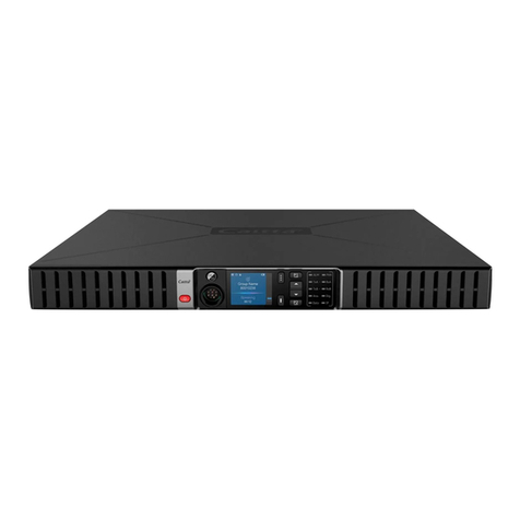
The KNX TP line coupler MECtp connects two TP lines as main line and
subline. MECtp can be used as KNX line coupler and KNX area coupler
or KNX repeater (without filtering). The lines have a galvanic separation
between each other. Operational and filtering states, malfunction and
faulty communication are indicated by LEDs.
MECtp is able to filter the traffic according to the installation place in
the bus system hierarchy and according to the built-in filter tables for
group oriented communication. Extended frames and long messages
with up to 240 bytes APDU length are supported. For commissioning
and troubleshooting a configurable Manual Function to temporarily
deactivate filtering is available. It can be activated by a single button
press and its switch-off after a pre-set time period is automatic
Suppress device configuration from the subline
Enable/disable filtering of Group telegrams or Physical telegrams
Number of repetitions is reducible
Confirmations can be added to sent out telegrams
Requirements of Directives EMC, RoHS and LVD are met. Standards for
residential, commercial, and industrial environments are fulfilled. The
full text of the EU declaration of conformity is available at the following
internet address: www.tapko.de/ce
Bus state KNX TP (Main line)
green: Main line OK
orange: Manual Function active
Bus state KNX TP (Subline)
green: Subline OK
Telegram traffic KNX TP (Main line)
green (blinking):
Telegram traffic extent
red (blinking):
Transmission error
Telegram traffic KNX TP (Subline)
green (blinking):
Telegram traffic extent
red (blinking):
Transmission error
Group Address routing
green: Filter active
orange: Route all
red: Block all
<off>: Main line / subline different
Function button
Physical Address routing
green: Filter active
orange: Route all
red: Block all
<off>: Main line / subline different
Programming button
KNX TP main line connector
Programming LED
red: Programming Mode active
KNX TP subline connector
Technical specifications
Power input
Power supply:
Current consumption:
Housing
Dimensions (HxWxD):
Mounting (IEC60715):
Width in space units:
KNX bus connections:
Weight:
Environmental conditions
Operating temperature:
Storage temperature:
Ambient humidity:
21…30 V DC SELV
< 10 mA
(from main line)
90 x 36 x 71 mm
35 mm top-hat rail (TH35)
2 modules at 18 mm
KNX connector (red/black)
for KNX TP main line & subline
62 g
-5…45 °C
-20...60 °C
5…93 % (non-condensing)
Electrical safety
Pollution degree (IEC60664):
Protection type (IEC60529):
Protection class (IEC61140):
Overvoltage category (IEC60664):
Approbation (ISO/IEC14543-3):
CE Marking
EU Directives:
Standards:
2
IP20
III
III
KNX-certified
LVD (2014/35/EU)
EMC (2014/30/EU)
RoHS (2011/65/EU)
EN50491-5-1
EN50491-5-2
EN50491-5-3
EN50581
EN61000-6-2
EN61000-6-3
Mounting, commissioning and safety notes
Installation and maintenance
After connection to the KNX bus system, the device works with its
default settings as intended
Warning: Do not connect to 230 V. The device is supplied by the
KNX bus and does not require any additional external power supply
The device may only be installed and put into operation by a
qualified electrician or authorized personnel
For planning and construction of electric installations the appropriate
specifications, guidelines and regulations in force of the respective
country have to be complied
For mounting use an appropriate equipment according to IEC60715
Installation on a 35 mm DIN rail (TH35)
Connect the KNX bus line as for common KNX bus connections with a
KNX bus cable, to be stripped and plugged into a KNX TP connector
Do not damage electrical insulations during connecting
Installation only in dry locations
Accessibility of the device for operation and visual inspection must be
provided
For changing the configuration use the ETS
The housing must not be opened
Protect the device from moisture, dirt and damage
The device needs no maintenance
If necessary, the device can be cleaned with a dry cloth
In the case of damage (at storage, transport) no repairs may be
carried out by unauthorized personnel
Configuration details and ETS database: www.tapko.de/mectp
1
2
3
4
5
A
6
B
C
7
D

Betriebs-/Montageanweisung
MECtp
Version/Veröffentlichung: R3.2 / November 2018
© 2001-2018 TAPKO Technologies GmbH
Im Gewerbepark A15, 93059 Regensburg, Germany
Hier enthaltene Daten können sich ohne vorherige Ankündigung ändern. TAPKO garantiert nicht die Richtigkeit und Vollständigkeit des Dokuments. Alle Rechte vorbehalten.
Produktbeschreibung
Anschlüsse, Tasten und LEDs
Der KNX TP Linienkoppler MECtp verbindet zwei TP Linien als Haupt-
und Nebenlinie. MECtp kann als Linienkoppler, Bereichskoppler oder
als Repeater (ohne Filterung) verwendet werden. Beide Linien sind
galvanisch getrennt. Betriebs- und Filterzustände, Fehlfunktionen und
fehlerhafte Kommunikation werden durch LEDs angezeigt.
Der MECtp kann die weiterzuleitenden Telegramme sowohl topologisch
als auch gruppenorientiert filtern. Extended Frames und lange
Telegramme werden mit bis zu 240 Byte APDU-Länge unterstützt. Für
Inbetriebnahmen oder zur Fehlersuche kann die Filterung mit einem
einzigen Tastendruck vorübergehend deaktiviert werden. Der MECtp
schaltet dann nach einer voreingestellten Zeitspanne automatisch
wieder auf Normalbetrieb zurück. Außerdem verfügbare Funktionen:
Blockieren von Gerätekonfigurierungen über die Nebenlinie
Filter für Physikalische und Gruppentelegrammen de-/aktivierbar
Anzahl der (Sende-)Wiederholungen reduzierbar
Hinzufügen von Bestätigungen zu abgehenden Telegrammen
Die Anforderungen der Direktiven EMC, RoHS und LVD sowie Standards
für Wohn & Gewerbebereiche als auch Industriebereiche werden erfüllt.
Der vollständige Text der EU-Konformitätserklärung ist unter der
folgenden Internetadresse verfügbar: www.tapko.de/ce
Busstatus KNX TP (Hauptlinie)
grün: Hauptlinie OK
orange: Manual-Funktion an
Busstatus KNX TP (Nebenlinie)
grün: Nebenlinie OK
Telegrammverkehr KNX TP (Hauptl.)
grün (blinkend):
Telegrammverkehr
rot (blinkend):
Übertragungsfehler
Telegrammverkehr KNX TP (Nebenl.)
grün (blinkend):
Telegrammverkehr
rot (blinkend):
Übertragungsfehler
Gruppenadressen Filter
grün: Filter aktiv
orange: Alle weiterleiten
rot: Alle blockieren
<off>: Haupt-/Nebenl. unterschiedlich
Funktionstaste
Physikalische Adressen Filter
grün: Filter aktiv
orange: Alle weiterleiten
rot: Alle blockieren
<off>: Haupt-/Nebenl. unterschiedlich
Programmiertaste
Anschluss der
KNX TP Hauptlinie
Programmier-LED
rot: Programmier-Modus an
Anschluss der
KNX TP Nebenlinie
Technische Angaben
Versorgung
Eingangsspannung:
Stromverbrauch:
Gehäuse
Maße (HxBxT):
Montage (IEC60715):
Breite:
KNX Bus-Anschlüsse:
Gewicht:
Umgebungsbedingungen
Arbeitstemperatur:
Lagertemperatur:
Umgebende Feuchte:
21…30 V DC SELV
< 10 mA
(von der Hauptlinie)
90 x 36 x 71 mm
35 mm DIN-Schiene (TH35)
2 TE zu je 18 mm
KNX Klemme (rot/schwarz)
für KNX TP Hauptlinie & Nebenlinie
62 g
-5…45 °C
-20...60 °C
5…93 % (nicht-kondensierend)
Elektrische Sicherheit
Verschmutzungsgrad (IEC60664):
Schutzart (IEC60529):
Schutzklasse (IEC61140):
Überspannungskategorie (IEC60664):
Freigabe (ISO/IEC14543-3):
CE Kennzeichnung
EU Direktiven:
Standards:
2
IP20
III
III
KNX-zertifiziert
LVD (2014/35/EU)
EMC (2014/30/EU)
RoHS (2011/65/EU)
EN50491-5-1
EN50491-5-2
EN50491-5-3
EN50581
EN61000-6-2
EN61000-6-3
Montage, Inbetriebnahme und Sicherheit
Installation und Wartung
Nach Anschluss an das KNX-Bussystem arbeitet das Gerät mit seinen
Standardeinstellungen wie vorgesehen
Warnung: Nicht an 230V anschließen. Das Gerät wird vom KNX-Bus
versorgt und benötigt keine zusätzliche externe Stromversorgung
Das Gerät darf nur von einer Elektrofachkraft oder autorisiertem
Fachpersonal installiert und in Betrieb genommen werden
Bei der Planung und Errichtung von elektrischen Anlagen sind die
einschlägigen Richtlinien, Vorschriften und Bestimmungen des
jeweiligen Landes zu beachten
Zur Montage ein geeignetes Werkzeug nach IEC60715 verwenden
Auf geeignete DIN-Hutschienen (TH35) montieren
Die KNX-Buslinie, wie für alle üblichen KNX-Anschlüsse, mit
abisoliertem KNX-Buskabel und KNX TP-Klemme anschließen
Beim Anschließen nicht die elektrischen Isolationen beschädigen
Installation nur bei trockener Umgebung
Die Zugänglichkeit zum Gerät muss aus Gründen der Bedienbarkeit
und Inspektion stets gewährleistet sein
Änderungen an der Konfiguration mit der ETS vornehmen
Das Gehäuse darf nicht geöffnet werden
Gerät vor Feuchtigkeit, Schmutz und Beschädigung schützen
Das Gerät ist wartungsfrei
Wenn nötig, das Gerät mit einem trockenen Tuch reinigen
Bei Beschädigung (bei Transport, Lagerung) darf keine Reparatur
vorgenommen werden; Gerät zurückschicken
Konfiguration-Details und ETS-Datenbank: www.tapko.de/mectp
1
2
3
4
5
A
6
B
C
7
D
Table of contents
Languages:
