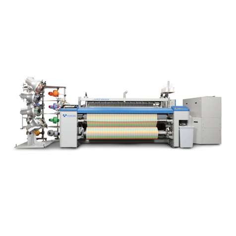
Toyota JAT810 User manual

JUNE, 2010 Ver. 2.01 (Towel)
TOYOTA AIR JET
WEAVING MACHINE
Towel Loom
Model JAT810
(FIRST EDITION)
Thank you for purchasing the JAT810 Air Jet Weaving Machine.
This instruction manual describes the correct installation, operating principles, function, adjustment, and
maintenance of the JAT810 motions, all of which should be familiar to all personnel concerned.
Before operating, adjusting, or maintaining the JAT810, be sure to read this manual carefully to understand
the JAT810.
Specifications, operating instructions, and dimensions in this manual are subject to change for improvements
without prior notice.
TOYOTA shall take no responsibility for loss, damage, expense or claims for bodily injury or property damage
arising from incorrect usage which is not in accordance with the instructions given in this manual.
In no event will TOYOTA be liable for products resulting from the use of this machine.
Introduction:
This manual is edited separately to provide instructions for towel looms. It consists of
Machine and Electrical Parts. For items not covered herein, refer to the “Instruction Man-
ual” for the standard looms (hereafter called Standard Machine “Instruction Manual”.)
Especially for matters related to safety, please first read Section S of the Standard
Machine “Instruction Manual”.
As to the contents of the items described in both of the two above-said manuals, give pri-
ority to this towel manual.

M1. Preparation for Setting .......................................................................................... M1-1
1.1 Yarn Beam Installation
1.2 Preparation of the Beam
1.3 How to Run the Warps and Woven Fabric Through
1.4 How to Remove/Reinstall the P-tension Shaft for
Easier New Fabric Weaving
M2. Shedding Motion ................................................................................................... M2-1
2.1 Dobby Shedding Specifications
2.2 Jacquard Shedding Specifications
M3. Temple .................................................................................................................. M3-1
3.1 Longitudinal Position of the Temple
3.2 Crosswise Position of the Temple
3.3 Vertical Position of the Temple
3.4 Standard Setting of the Temple Ring
3.5 Vertical Position of the Temple Cover
3.6 Adjustment of Fell Plate Position
M4. Selvaging Machine................................................................................................ M4-1
4.1 Leno Weave with Two Clockers
4.2 Trimmed Selvage Motion
4.3 Gripper
M5. Pile Let-Off ............................................................................................................ M5-1
5.1 Pile Let-off Mechanism
5.2 Outline of Let-off Control
5.3 Adjustment of Easing Roller
5.4 Adjustment of Electronic Terry Motion Type Let-off Pile Beam Tube Diameter Sensor
M6. Torsion Back ......................................................................................................... M6-1
6.1 Advance Adjustment
6.2 Adjustment at the Change of Gland Warp Tension
6.3 Machine Stop or Disabled Operation due to Abnormal Tension
6.4 Height Adjustment
M7. Warp Stop Device ................................................................................................. M7-1
7.1 Longitudinal Position
7.2 Vertical Position
CONTENTS
Section 1 Mechanical
Section 2 Electrical

M8. Lubrication ............................................................................................................ M8-1
8.1 Lubrication Cycle and Applicable Fluids
8.2 Oil Change of Terry Motion Cam Box
8.3 Oil Change of Jacquard Bevel Gearbox
M9. Electronic Terry Motion......................................................................................... M9-1
9.1 Adjusting the Stoppers
9.2 Zero-point Restoration Proximity Switch
9.3 Reverse Current Absorber Cover
9.4 Lubrication of Terry Motion Gear Box
E1. State of Indicator Lamps and Mode Display .......................................................... E1-1
E2. Setting of Towel Loom-related Function Panel...................................................... E2-1
2.1 Towel Screen Setting Method
2.2 How to Set [ PILE ]
2.3 Pattern Initialization
E3. Setting and Operation of Towel Loom Beam-related Function Panel.................... E3-1
E4. Electric Components / Let-off Motions for A Towel Loom...................................... E4-1
4.1 Electric Components
E5. Instrumentation and Electronic Jacquard for Towel Weaving Machine ................. E5-1
E6. Electronic Terry Motion.......................................................................................... E6-1

Section 1 Mechanical
M1 - 1
M1. Preparation for Setting
1.1 Yarn Beam Installation
[ 1 ] Gland beam installation
(1) [Installation on the yarn beam gear side]
Mark the yarn beam 190 mm from side “a”
with a felt-tipped pen, etc.
(2) Screw in a yarn beam flange 2from direction
A. Set the inside of the flange to the marked
position.
•For the ease of screwing, apply grease or
oil to the threaded portion.
(3) Set a yarn beam gear 4to the yarn beam 1so
that the bolt holes (large, 8 holes) of the yarn
beam gear 4match the bolt holes of the yarn
beam 1. Then turn the yarn beam flange 2so
as to have the bolt holes (small, 3 holes)
match the bolt holes on the yarn beam flange
2.
(4) Tighten the yarn beam 1and yarn beam gear
4with 8 bolts 8. Then match the bolt hole posi-
tion of the yarn beam gear 4with the yarn
beam flange 2. Tighten 3bolts 7sequentially
and equally.
Section 1 Mechanical

M1. Preparation for Setting
M1 - 2
(5) [Flange installation on the side of the counter-
yarn beam gear]
Mark the yarn beam 1at a point the reed
drawing width of Lmm to the right of the mark-
ing made in (1).
NOTE: A minimum effective drawing width to
each nominal reed width is a nominal reed
width minus 70 cm.
(6) Screw in the yarn beam flange 3from direction
B. Match the marking made in (5) to the inside
of yarn beam flange 3.
•For the ease of screwing, apply grease or
oil to the threaded portion.
(7) Screw in the flange ring 5also from direction
B. Match the bolt holes of the yarn beam
flange 3and flange ring 5by providing a clear-
ance of 3 to 5 mm between the end faces of
the yarn beam flange 3and flange ring 5and
tighten the bolts.

Section 1 Mechanical
M1 - 3
[ 2 ] Pile beam installation
(1) [Installation on the side of the yarn beam gear]
Mark the yarn beam 1107.5 mm from the side
“a”with a felt-tipped pen, etc.
(2) Screw in the yarn beam flange 2from direction
A. Set the inside of the flange to the marked
position.
•For the ease of screwing, apply grease or
oil to the threaded portion.
(3) Set the yarn beam gear 4to yarn beam 1so
that the bolt holes (large, 8holes) of the yarn
beam gear 4match the bolt holes of the yarn
beam 1. Then turn the yarn beam flange 2so
as to have the bolt holes (small, 3holes)
match the bolt holes on the yarn beam flange
2.
(4) Tighten the yarn beam 1and yarn beam gear
4with 8bolts 8. Then match the bolt hole posi-
tions of the yarn beam flange 2and yarn beam
gear 4. Tighten 3bolts sequentially and
equally.

M1. Preparation for Setting
M1 - 4
(5) [Flange installation on the side of the counter-
yarn beam gear]
Mark the yarn beam 1at Lmm [reed drawing
width minus (2* selvage texture width) plus 0
to 10 mm] to the right of the marking made in
(1).
NOTE: A minimum effective drawing width to
each nominal reed width is a nominal reed
width minus 70 cm.
(6) Screw in the yarn beam flange 3from direction
B. Match the marking made in (6) to the inside
of yarn beam flange 3.
•For the ease of screwing, apply grease or
oil to the threaded portion.
(7) Screw in the flange ring 5also from direction
B. Match the bolt holes of the yarn beam
flange 3and flange ring 5by providing a clear-
ance of 3 to 5 mm between the end faces of
the yarn beam flange 3and flange ring 5and
tighten the bolts.
[ 3 ] Bearing installation
(1) Mark the point Abelow from inside a bearing
shaft 9:
(2) Insert a bearing 10 to the bearing shaft 9.
(3) Insert a hoop 11 so as to have the inside of the
bearing 10 matches the marking made in (1).
Then tighten the bolt 12 to position the bearing
10.
(4) Bearing shaft 9is attached to the machine.
Remove bolt 13 and bearing shaft 9from the
empty yarn beam when replacing the beams.
Gland beam Beam gear side 25.5mm
Counter beam gear side 28.0mm
Pile beam Beam gear side 92.5mm
Counter beam gear side 65.0mm

Section 1 Mechanical
M1 - 5
1.2 Preparation of the Beam
[ 1 ] Preparation of gland beam
Wind the gland beam 1counterclockwise from the
beam gear side A.
[ 2 ] Preparation of pile beam
Wind a pile beam 2clockwise from the beam gear
side A.
Care should be taken for the direction of wind-
ing of the gland beam 1and pile beam 2which
run counter to each other.
Care should be taken for the direction of wind-
ing of the gland beam 1and pile beam 2which
run counter to each other.

M1. Preparation for Setting
M1 - 6
1.3 How to Run the Warps and Woven Fabric Through
(1) How to run the gland warps through
Run the warps to a gland warp dropper 2via a
torsion bar roller 1. Allow them to pass
between a pile warp dropper 3to reach a
heald 11 and a reed 12.
(2) How to run the pile warps through
Run the warps along a deflector roller 4and
via a shock absorber bar 5to a pile easing
roller 6. Run them to the heald 11 and reed 12
through the pile warp dropper 3.
(3) How to run woven fabric
Wind woven fabric on a surface roller 8via an
expansion bar 7. Wind it on a cross roller 10
by allowing it to pass over the press roller 9.
1) Surface roller
NOTE: Danger. Beware of a number of spikes
embedded to the surface of the surface roller
8. Care should be taken when working near
the surface roller 8.
2) Cross roller
Wind woven fabric on to a cross roller 10.
Press it with apress roller 13 to insert the fabric
to the groove.
A: Gland beam
B: Pile beam
a: Gland yarn
b: Pile yarn
NOTE: During the setting, terry motion can be
stopped by selecting texture weaving mode with
the function panel.

Section 1 Mechanical
M1 - 7
1.4 How to Remove/Reinstall the P-tension Shaft for
Easier New Fabric Weaving
At the new fabric weaving, removing top cross rail
1, back roller 5, and P-tension shaft 6makes it eas-
ier to set the reed, heald frames, and droppers to
the weaving machine.
(1) Remove bolts 3from right and left clamps 2on
top cross rail 1.
NOTE: Do not loosen or remove bolts 4.
(2) Take out back roller 5.
(3) Make a note of the mounting angle of the leaf
spring, and then loosen bolts 8on coupling 7.
(4) Slide the coupling 7in the direction of arrow A.
(5) Remove bolts 10 from holder 9and take off the
holder.
(6) Remove P-tension shaft 6.
(7) Set the reed, heald frames, and droppers to
the weaving machine.
(8) Put P-tension shaft 6on the bracket.
(9) Fit coupling 7onto P-tension shaft 6until cou-
pling 7comes into contact with the stop ring,
while pressing shaft 6in the direction of arrow
Aand sliding coupling 7in the direction of
arrow B.
(10) Hold the leaf spring at an angle recorded in (3)
and secure coupling 7with bolts 8.
(11) Secure holder 9with bolts 10.
(12) Place back roller 5.
(13) Put top cross rail 1on the bracket.
(14) Tighten bolts 3.
(15)
After start of new fabric weaving, set the pile ten-
sion. Then loosen bolts
8
on coupling
7
and
adjust the angle of the P-tension roller again so
that the warp sheet at section “
C”
becomes
almost horizontal.
(16) Check that bolts 3, 4, 8, and 10 are tightened
to the specified torques.
3
4
3
1
6, 7
5
3
4
3
2
1
7
69
10
10
B
A
8
The reed, heald frames and droppers are very
heavy, so take extra care when handling them.
In (16), tighten bolts to the torque values spec-
ified in the Standard Machine “Instruction Man-
ual,” Chap. M, Subsect. M.1.9.
M1. Preparation for Setting
M1 - 8
Clean the pile yarn contact part on the board
panel and the guide bar at every beam
change, and confirm that no foreign substance
is attached. (This is to avoid a thread being
adhered by a substance such as paste that
adversely affects and tension.)

Section 1 Mechanical
M2 - 1
M2. Shedding Motion
2.1 Dobby Shedding Specifications
For basic handling method, please refer to Stäubli’s Instruction Manual.
2.1.1 Setting the Heald Frame Height
and Shed Size
See “Appendix 6. Stäubli’s Positive Dobby (Type
S3220)” for the heald frame height and shed size
setting procedures.
This section introduces the following reference val-
ues for the towel looms.
Reference setting value list
NOTE (list specifications) :
1. Heald frame: C type riderless 330 MM
Center mail, Dimension H: 549 MM (Stave
width standard)
2. Heald frame height Ais the value at the close
timing (center shed).
3. If dimension His different, add or subtract 1/2
of the difference to or from dimension A. If the
heald is 5 mm up, subtract 5 mm from the
specified dimension A.
4. The maximum shed size is 95 mm for the
Klöcker half-leno device.
C
A
H
Shedding
lever
Pile Leno weave Waste
selvage Ground
Frame
No.
Dimen-
sion
C
(mm)
Dimen
sion A
Frame
height
(mm)
Dimen-
sion
C
(mm)
Dimen
sion A
Frame
height
(mm)
Dimen-
sion
C
(mm)
Dimen
sion A
Frame
height
(mm)
Dimen-
sion
C
(mm)
Dimen
sion A
Frame
height
(mm)
1 129 71
2 109 67
39164
47360
5 103 64
69061
77558
8 109 56
912960
10 120 58
11 109 56
12 99 53
13 89 51
14 78 49
15 69 46
16 59 44

M2. Shedding Motion
M2 - 2
2.2 Jacquard Shedding Specifications
Refer to the instruction manual of Jacquard shedding motion for the handling method.
2.2.1 Height of Top Rail Bracket
(1) Loosen a nut 4.
(2) Loosen a bolt 2.
(3) Turn an adjust bolt 3and adjust a height Aof a
top rail bracket 1.
(Standard dimension of height Ais 55 mm.)
(4) Tighten the bolt 2to fasten top rail bracket 1.
(5) Tighten the nut 4.
2.2.2 Hanging of Draw Yarn
1) The left end position of draw yarn is 200 mm
from the machined face inside the L.H. frame.
2) Determine the longitudinal position of draw
yarn bysetting heald No. 1 to a point 43 mm
from the rear face of the rocking shaft.
1
2
2
A4
3

Section 1 Mechanical
M3 - 1
M3. Temple
Movable temple
A moving cloth fell produces pile.
NOTE: To make the temple movement smooth, a bearing 4is installed to a temple base bracket 3. Accord-
ingly, check that all thetemple guides 5are constantly in contact with the bearing 4
3.1 Longitudinal Position of the Temple
(1) Set the crank angle to 0° in fast pick.
(2) Lock the emergency stop push-button switch.
(3) Check clearance dimension “a” between the
temple and reed.
3 to 4 mm when the warp tension is not applied
2 to 3 mm when loaded with warp tension
(4) If the clearance is different between the left
and right, loosen expansion bar rod
1
fasten-
ing nut
2
(two pieces each on the left and right
sides).
Turn the extension bar rod nut left and right to
adjust the longitudinal position of the temple to
equalize the clearance.
NOTE:
Pay attention to the intervals of the
stoppers to the left and right of the cloth fell.
(See M5.2 Stopper Adjustment) Adjust inter-
val “
a
” correctly.
The red may be damaged if in contact with the
yarn guide plate during operation. Difference
of interval “
a
” in the longitudinal direction will
result in the difference of the pile length, addi-
tionally causing fallen warp due to loose warp.
(5) If the clearance is the same on the left and
right sides, turn turnbuckle 6 of the terry
motion lever for adjustment.
NOTE:
Pay attention to the intervals of the
stoppers to the left and right of the cloth fell.
(See M5.2 Stopper Adjustment) Adjust inter-
val “
a
” correctly.
(6) Release the emergency stop push-button
switch. Check by inching operation that the
yarn guide plate is not in contact with the reed.
a
6
3
4
5
12

M3. Temple
M3 - 2
3.2 Crosswise Position of the Temple
[ 1 ] Left-hand side of the loom
(1) Loosen the bolts
2
(8 bolts) of a temple case
1
.
(2) Move the temple case
1
so that a clearance
“
a
” between the left-hand side
A
of a temple
ring
3
and a gripper
4
becomes 0.5 mm.
(3) Tighten the bolts
2
to fix the temple case
1
.
[ 2 ] Right-hand side of the loom
(1) Pull the warp drawn through the reed toward
you at a right angle to a reed
5
.
(2) Set the temple
7
so as to have the right-hand
end of No. 1 ring
8
of the temple
7
aligned to
the right-hand end
6
of the warp.
(3) After the setting, check that the right-hand end
of a fabric is held with the whole surface of No.
1 ring
8
.
If not held with the whole surface, readjust.
When readjusted, readjust a cutter lever.
(4) To change the drawing width of a reed, loosen
the fastening bolts
9
(6 bolts) to move the tem-
ple
7
to a prescribed position, then tighten the
bolts
9
to fix it.

Section 1 Mechanical
M3 - 3
3.3 Vertical Position of the Temple
(1) Adjust the height of the left- and right-hand
temples with the number of the shims
1
between a temple bracket
2
and the temple
base
3
.
Adjust the number of shims by loosening 8
bolts on the left-hand side and 6 bolts on the
right-hand side.
The standard number of shim is one shim of 1
mm.
(2) It is necessary to have a right-hand side cutter
shaft bracket
4
at the same height with the
temple base
3
. Insert the same number of
shims inserted between the cutter shaft
bracket
4
and the temple base
3
in (1).
To adjust, loosen the bolts
5
(2 bolts).
The standard number of shim is one shim of 1
mm.
3.4 Standard Setting of the Temple Ring
(1) Loosen the bolt
2
to turn the temple ring
1
so
as to have a marked line
x
to the top. Tighten
the bolt
2
to fix the temple ring.
•
To provide the temple with a harder pull, set
the marked line
x
to the counter-reed side.
NOTE:
Care should be taken, however, since
loose warp will result if the end of the fabric
falls from the end of the temple.
•
To weaken the temple pull, set the marked
line
x
to the side of the reed.

M3. Temple
M3 - 4
3.5 Vertical Position of the Temple Cover
(1) Loosen a bolt
3
.
(2) Make the top face
A
of the temple cover
1
flush with the top face
B
of the temple cover
2
.
(3) Tighten the bolt
3
to fix the temple cover.
3.6 Adjustment of Fell Plate Position
(1) Loosen a bolt
2
that fixes a fell plate
1
.
(2) Set the height of a fell plate
1
(height differs by fabric).
[Tentative adjustment]
Set the height of the fell plate
1
so that it will
be 6 mm vertically from the face
A
of a fell
plate bracket
3
. At this time, check that the
lower face of the temple cover
4
and the top
face of the fell plate
1
are at the same height.
[Fine adjustment]
Set the upper jaw of reed
5
and the fabric sur-
face
6
so that they will have a clearance of 1
mm in the plain weaving state.
(3) Determine the left- and right-hand positions so
that the fell plate
1
will be 3 to 4 mm inside the
cover than a face
B
of the temple cover
4
on
both the left-hand and right-hand sides of the
loom.
(4) Fix the fell plate
1
by tightening the bolt
2
.
NOTE:
Decide the length of fell plate
1
accord-
ing to the weaving width, and then cut and
remove the rest. Finish the section smooth
with tools such as a file to prevent persons
from injury or a yarn from getting stuck.
Never operate the loom during the above work.
Otherwise, your hand may be caught between
the reed and temple cover
1
.
1
2
3
56

Section 1 Mechanical
M4 - 1
M4. Selvaging Machine
4.1 Leno Weave with Two Clockers
Install a leno weave selvage motion to two heald
frames for dobby weave specification or connect it
to a harness for jacquard weave specification.
With the up and down motion of the heald frames
A
and
B
, cross yarns form the selvage texture by
moving to the left and right to a stationary yarn
3
which is placed through the eye of a part
1
.
For the texture of the leno weave selvaging motion,
use a plain weave texture as shown in the figure to
the left.
4.1.1 Installation of Clocker
(1) Lock the emergency stop pushbutton switch.
(2) Install the clockers
1
and
2
to the heald frames
A
and
B
.
NOTE:
A maximum shedding amount of the clock-
ers for a 330 mm center mail is 95 cm. Care should
be taken when setting the shedding.
Dobby weave specification
Jacquard weave specification

M4. Selvaging Machine
M4 - 2
For multiple tucking jacquard
(1) Metal fitting number
1
is applied to stabilize the
right and left position of leno weave with two
clockers
Model number J5211-02010-00 PLATE,
KLOCKER 4 pcs/place
4.1.2 How to Run the Selvage Yarns
(1) Run a yarn from a bobbin
1
through a bobbin
stand
2
and then through the thread eye via
tenser
3
.
(2) Pass the yarn from the thread eye
4
through
the eye of a tenser spring
5
then through a
gland dropper box
A
(put through the dropper).
(3) Pass the yarn between a pile dropper box
B
,
through a yarn retainer device
6
then through
a clocker device
7
. (For how to run the yarn
through the clocker, read M4.1 Leno Weave
with Two Clockers.)
Jacquard
harness
1
1
2
34
3
4

Section 1 Mechanical
M4 - 3
4.1.3 Yarns for Leno Weave Selvaging
Motion
(1) Since leno weave has a number of yarn cross-
ings, fine yarns of good quality and high tenac-
ity with lesser fluffs and knots should be used
as principle.
(2) A cotton double (or triple) yarns of a higher
count than the warps for plain weave is recom-
mended.
(3) If the same yarn as the one for ground weav-
ing may cause insufficient strength, select
another yarn whose physical property is as
similar as possible. If a yarn different in quality
from the warp for ground weaving is to be
used, perform preparatory check to cause no
trouble in later processing.
4.2 Trimmed Selvage Motion
Located outside the right-hand end of the fabric, the
trimmed selvage motion entwines a weft
1
shuttled
and several warps
2
for trimmed selvage (yarns
from the trimmed selvage stand) to provide the weft
with tension to form a fabric of normal woven tex-
ture.
Other manuals for JAT810
2
Table of contents
Other Toyota Weaving manuals