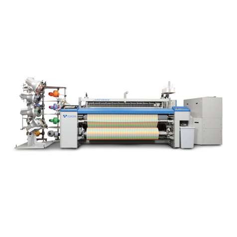
Toyota JAT710 User manual

1
Issued: AUGUST, 2008 Ver. 1.30
Profile Reed System
TOYOTA AIR JET WEAVING MACHINE
INSTALLATION GUIDE
(FIFTH EDITION)
Thank you for purchasing the JAT710 Air Jet Weaving Machine.
This installation guide describes the work required for your weaving machines from their delivery through
installation, including necessary preparations before starting production.
Make preparations according to the time schedule as instructed in this guide so that you can have everything
ready when our service personnel arrive. This will eliminate wasted time and efforts. If preparations are not
completed, our service personnel will have to leave and come back again at a later date.
If you have any questions concerning the installation, please contact us at the following locations:
Notice: Specifications, operating instructions, and dimensions in this manual are subject to change for
improvements without prior notice.
TOYOTA shall take no responsibility for loss, damage, expense or claims for bodily injury or property damage
arising from incorrect usage which is not in accordance with the instructions given in this manual.
Please also understand that we will not be held responsible for the result of operating this machine.
Model JAT710
HEAD OFFICE: TOYOTA INDUSTRIES CORPORATION
TEXTILE MACHINERY DIVISION
1, Toyodacho 2-chome, Kariya-shi, Aichi, 448-8671 JAPAN
PHONE: +81 566 27 5316
FACSIMILE: +81 566 27 5301
TOKYO BRANCH: 29th Floor, Marunouchi Bldg.
4-1, Marunouchi 2-chome, Chiyoda-ku, Tokyo, 100-6329 JAPAN
PHONE: +81 3 5293 2500
FACSIMILE: +81 3 3218 0070
OSAKA BRANCH: Room 506, Toyoda Bldg.
3-11, Minamisenba 4-chome, Chuoh-ku, Osaka, 542-0081 JAPAN
PHONE: +81 6 6251 3543
FACSIMILE: +81 6 6251 3573

2
This manual uses the following symbols: WARNING, CAUTION, .
(1) WARNING
The WARNING symbol is used in this manual, alerting you to a situation that might cause serious
injury or death to the worker if he or she does not follow the instructions in this manual necessary to avoid
any dangers in the machinery.
(2) CAUTION
The CAUTION symbol is used in this manual, alerting you to a situation that might cause minor
injury to the worker if he or she does not follow the instructions in this manual necessary to avoid any
dangers in the machinery.
(3)
The mark is used here, alerting you to possible substantial property damage if the worker
fails to follow the instructions in this manual.
ATTENTION
ATTENTION
ATTENTION

3
CONTENTS
OUTLINE OF INSTALLATION WORK........................................................................................... 5
Chapter S. SAFETY
S.1 Safe Work ...................................................................................................................................... 8
S.1.1 Rules for Installation Work .................................................................................................... 8
S.1.2 Rules for Safe Operation ..................................................................................................... 13
S.1.3 Rules for Maintenance ........................................................................................................ 15
S.1.4 Rules for Operating or Checking the Electrical Devices...................................................... 17
Chapter 1. PREPARATIONS FOR INTRODUCING THE MACHINE
1.1 Building ........................................................................................................................................ 20
1.2 Foundation Work.......................................................................................................................... 22
1.2.1 Structure of Foundation ....................................................................................................... 22
1.2.2 Laying the Foundation for Wiring and Piping ...................................................................... 23
1.2.3 Floor Surface Conditions ..................................................................................................... 23
1.2.4 Preparing Glue or Quick-hardening Cement ....................................................................... 23
1.2.5 Marking on the Floor ........................................................................................................... 26
1.2.6 Laying Anchor Bolts (Only for the bolting installation method)............................................ 26
1.3 Wiring (for looms other than towel weaving machine) ................................................................. 33
1.3.1 In-plant Electric Facilities..................................................................................................... 33
1.3.2 Circuit Breakers ................................................................................................................... 35
1.3.3 Cable Capacity .................................................................................................................... 37
1.3.4 Cable Capacity Calculation Examples (reference examples).............................................. 40
1.3.5 Group Inverter ..................................................................................................................... 45
1.3T Wiring (for towel weaving machine) ............................................................................................. 48
1.3.1 In-plant Electric Facilities..................................................................................................... 48
1.3.2 Circuit Breakers ................................................................................................................... 49
1.3.3 Cable Capacity .................................................................................................................... 51
1.3.4 Cable Capacity Calculation Examples (reference examples).............................................. 53
1.4 Air Compressor ............................................................................................................................ 54
1.4.1 Compressed-air Requirements for Air Jet Weaving Machines and
Precautions for Piping ......................................................................................................... 54
1.4.2 Choice of Air Compressor Type and the Number of Compressors ..................................... 54
1.4.3 Layout Examples of Air Compressors and Related Equipment........................................... 57
1.4.4 Piping .................................................................................................................................. 58
1.5 Other Equipment .......................................................................................................................... 60
1.5.1 Temperature Control and Air Conditioning .......................................................................... 60
1.5.2 Lighting ................................................................................................................................ 60
1.5.3 Prevention from Fly, Fleece, and Dust ................................................................................ 60
1.5.4 Separate Take-up Motion .................................................................................................... 61

4
Chapter 2. INSTALLATION WORK
2.1 Preparations for Installation.......................................................................................................... 64
2.1.1 Arrangement of Workers ..................................................................................................... 64
2.1.2 Setting-up of Unpacking and Carrying-in Tools ................................................................... 64
2.1.3 Preparation of Piping ........................................................................................................... 64
2.2 Installation Work........................................................................................................................... 65
2.2.1 Positioning of the Weaving Machine ................................................................................... 65
2.2.2 Jobs to be Done before Securing the Legs of the Weaving Machine.................................. 65
2.2.3 Installation ........................................................................................................................... 65
2.2.4 Wiring and Piping to Weaving Machines ............................................................................. 70
Chapter 3. PREPARATIONS FOR WEAVING START-UP
3.1 Warp-related Preparations ........................................................................................................... 74
3.1.1 Mounting the Warp Beam(s) and Procuring Warp Yarn ...................................................... 74
3.1.2 Preparing the Droppers ....................................................................................................... 78
3.1.3 Preparing the Healds........................................................................................................... 79
3.1.4 Preparing the Reed and Drawing in Warp ........................................................................... 81
3.1.5 Preparations for Selvage Construction ................................................................................ 83
3.1.6 Preparations for Waste Selvage Device .............................................................................. 86
3.2 Weft-related Preparations (Mainly Spun Yarn)............................................................................. 88
3.2.1 Preparing Weft Yarn and Cheeses ...................................................................................... 88
3.3 Lubricants, Cleaning Oil, and Sealant .......................................................................................... 89
3.3.1 Lubricants ............................................................................................................................ 89
3.3.2 Cleaning Oil and Sealant..................................................................................................... 93
Chapter 4. APPENDIX
4.1 JAT710 Technical Information...................................................................................................... 96
4.1.1 Nominal Reed Space and Effective Drawing-in Width......................................................... 96
4.1.2 Machine Weight (excluding EDP)........................................................................................ 96
4.1.3 Yarn Number Count of Warp ............................................................................................... 97
4.1.4 Picking Density .................................................................................................................... 97
4.1.5 Warp Tension Setting Range .............................................................................................. 97
4.1.6 Possible Weaving Range (Yarn density vs. Yarn number count) ........................................ 97
4.1.7 Fabric Examples.................................................................................................................. 98
4.2 TMS (TOYOTA MONITORING SYSTEM) ................................................................................... 99
4.2.1 Scope of your work.............................................................................................................. 99
4.2.2 Network Connection Concept ............................................................................................ 101
4.2.3 Network Design ................................................................................................................. 103
4.2.4 Piping Work ....................................................................................................................... 111
4.2.5 Wiring Sample Diagram..................................................................................................... 113
4.2.6 Network Cable Connector Installation Method .................................................................. 114
4.2.7 Network Cable Connection to JAT710 .............................................................................. 117
4.2.8 Connection with Customer’s Network................................................................................ 118

5
4.3 TMS Scanner (TOYOTA MONITORING SYSTEM SCANNER) ................................................ 122
4.3.1 TMS Scanner Overview .................................................................................................... 122
4.3.2 Features of TMS Scanner ................................................................................................. 123
4.3.3 Connection between Looms and Data Collection Boards (LTB3) ..................................... 126
4.3.4 Studying Loom Connection to TMS Scanner PC .............................................................. 130
4.3.5 Works after Determining TMS Scanner Introduction ......................................................... 134
4.4 Manufacturers of Weaving-related Machines............................................................................. 136

6
OUTLINE OF INSTALLATION WORK
Items marked with a box are jobs which you should do. Use the list given below as a check list.
1. Preparations for Introducing the Machine
Complete the following preparations:
Building construction and floor work (Irregularity in the floor levelness: 5 mm or less, Surface irregularities of the
floor where the legs of the machine are to be positioned: 1 mm or less)
Foundation work, floor marking, and anchor bolt laying work*
(* This job is not required if you select the gluing installation method.)
Power wiring (to the installation position of machines) and installation of circuit breakers on the switchboard
Pneumatic piping (to the installation position of machines)
Installation of air compressor(s)
Air-conditioning work
2. Preparations for Installation
Complete the following preparations:
Arrangement of workers
Setting-up of forklift, hand lifts, and small jacks
Procurement of Polymortar (for bolting installation) and Araldite or Sikadur (for gluing installation)
Customs clearance for machines
Receiving and carrying machines to your factory
Installation can be started at this stage. Toyoda service personnel can be
dispatched at this stage.
3-1. Installation of Weaving Machines and Related
Facilities
Complete the following preparations under the on-site
supervision of Toyoda service personnel:
Unpacking and installation of machines
Leveling of machines
Installation of EDP stand(s)
Installation of cheese stand(s)
Power wiring to machines
(main power and inverter power)
Pneumatic piping to machines
3-2. Preparations for Weaving Start-up
Complete the following preparations:
Warp yarn preparation
Procurement of weft yarn, leno yarn,
waste-selvage yarn, and additional yarn
Installation of winder for weft cheeses
Installation of leno yarn winder
Installation of waste-selvage yarn winder
Procurement of oil and grease
Adjustment and Trial Run
Weaving Start-up
Start of Production

Chapter S.
SAFETY
S.1 Safe Work .................................................................................. 8
S.1.1 Rules for Installation Work............................................... 8
S.1.2 Rules for Safe Operation ............................................... 13
S.1.3 Rules for Maintenance .................................................. 15
S.1.4
Rules for Operating or Checking the Electrical Devices
.... 17

S. SAFETY
8
S.1 Safe Work
S.1.1 Rules for Installation Work
[ 1 ] Before Installation
(1) Check the safety rules and the workmanship standards for the plant.
(2) Make sure that all personnel involved know the nature of the job and the installation procedure, and
agree as to the best way to get them done.
(3) For jobs requiring a group effort, choose a supervisor whose instructions should be followed thoroughly
by all.
(4)
For jobs requiring a group effort, agree beforehand on words or gestures for giving and confirming signals.
(5) Wear safety shoes.
(6) Check the work places and their surroundings. If any unsafe point is found, take the necessary action to
make it safe.
For example
1) When anchor bolts, power cable conduits and
air inlet piping are spread out before installa-
tion, mark them clearly with brightly colored
cloth or a flag so that workers can avoid trip-
ping or hitting the machine and carriers
against them during installation.
2) If there is any unstable footing due to any pits
(for exhaust, piping, wiring, or other purposes)
which are dangerously uncovered, put on a
temporary cover to prevent falling accidents.
3) Use specified tools matched to the job to be
done.
Introduction
There is no such thing as a perfectly safe machine when improper handling or
ignoring precautions stands in the way. Any incorrect usage could possibly
result in a serious bodily injury, in the worst case it could cause death, and/or
substantial property damage.
TOYOTA has done everything possible to assure optimum safety. However, it
cannot be completed without your understanding and efforts.
It is impossible for the manufacturer to take into account individual operating
conditions of the machinery at the user site and prepare an instruction manual
covering all information relating to the machine operation. We, therefore, ask
you to establish your own individual safety standards for each safe job of instal-
lation, operation, adjustment, and maintenance, by referring to this guide.

S.1 Safe Work
9
[ 2 ] During Installation
[ 2.1 ] General points for installation work
(1) Always wear a helmet whenever installation is
being carried out at the same time as other
jobs, such as construction and piping.
(2) Always wear gloves whenever there is the
possibility of injuring hands or fingers.
(3) Never use gloves if there is the possibility of
their becoming caught in a rotating section of
the machine.
(4) Never get oil or grease on the floor, since
these can cause slipping accidents.
(5) Always provide a stable platform or scaffold for
those jobs in places too high to reach from the
floor.
(6) Never climb onto a heavy hoisted object nor
get under it.
(7) Keep your tools, parts, devices and instru-
ments neatly arranged, and observe the fol-
lowing rules:
1) Put them where they are not likely to fall down.
2) Whenever standing or leaning them against
something else, do what is necessary to pre-
vent them from falling over.
3) Whenever piling round bars or pipes, do what
is necessary to prevent them from falling
down.
(8) Observe the following rules when conducting a
group effort:
1) Choose a supervisor whose instructions
should be followed thoroughly by all.
2) Agree beforehand on words or gestures for
giving and confirming signals.
3) Be especially careful when handling heavy
objects. If the weight exceeds 20 kg, two or
more workers should handle them.

S. SAFETY
10
[ 2.2 ] Transport
(1) Before bringing in machinery, always prepare
well-maintained carriers.
(2) Never lift the machine or load any higher than
200 mm above the floor during transport.
(3) Never stand in small spaces between the
machine/load and the wall during transporta-
tion.
(4) Always assign a guide and transport according
to his or her instructions.
The guide should pay sufficient attention to
any protruding parts on the transport route.
(5) Whenever inserting wooden blocks under the
machine/load, never let fingers get between
the machine/load and floor.
(6) Always push hand carts when carrying loads.
Never pull them.
(7) Fix the load with a rope or other means if nec-
essary, to prevent the load from falling down
during transport.
(8) When putting a lift beneath the machine, make
sure that its hook catches the place between
the back and front cross rails and balances it
right and left securely.
Carriers Q'ty Specifications
Forklift
(or wrecker) 13.5 t
(Reed space:150-190 cm)
Hand lift 2 3.0 t or more
Small jack 2 1.5 t or more
Wooden block 4 Approx. 90 ×150 ×60 mm

S.1 Safe Work
11
[ 2.3 ] Unpacking and cleaning
(1) Parts are coated with rust-preventive oil. Take
necessary action so they will not slip when
carrying them.
(2) When washing parts, use waterproof paper to
prevent the floor from becoming stained.
(3) Use Nippon Oil Corporation's New-sol Deluxe
or equivalent cleaning fluid. Never use trichlo-
roethylene-base cleaning fluid; otherwise, the
painting will peel off or discolor.
(4) Never put anything on the parts storage area,
passages, or footing area.
[ 2.4 ] Levelling work
(1) When using a small jack, apply it to two points
underneath the front and back cloth rails and
make sure that it catches them securely.
(2) When conducting a group effort, agree before-
hand on words or gestures for giving and con-
firming signals.
(3) Whenever inserting fiber packings under the
bottom of the machine’s feet or removing them
during the levelling work, never let fingers get
between the packings and the floor.
[ 2.5 ] Wiring work
(1) Never allow non-qualified workers to carry out
connection or disconnection of the primary
power lines.
(2) Before starting wiring work, be sure to check
that the main circuit breaker is open and the
warning notice (tag) is put up for all to see.
(3) Before starting wiring work, be sure that the
line is not active.
(4) Check that the plant power grounding line is
connected to the PE terminal in the control
box.
(5) Check the wiring and connection for no abnor-
mality.

S. SAFETY
12
[ 3 ] Before Trial Run
(1) Clear away bolts, nuts, tools and other unnec-
essary things around, on and under the
machine.
(2) Check that all sections of the machine are
securely tightened and that the safety covers
are on.
[ 4 ] During Trial Running
(1) Check the rotating direction for: the main
motor, drum motor, and electrical let-off motor.
Also check the rotating direction of forward/
reverse inching.
(2) Check the functions of each of the stop
motions and limit switches.

S.1 Safe Work
13
S.1.2 Rules for Safe Operation
[ 1 ] General Rules
[ 1.1 ] Absolute precautions
(1) Never allow non-qualified workers to carry out
connection or disconnection of the primary
power lines.
(2) Never try live-wire operation when changing
the wiring on the machine.
(3) Never start the machine without communicat-
ing your intention to co-workers or without con-
firming their answer to your signal.
(4) Never touch rotating or operating parts until
the machine comes to a complete stop.
(5) Never operate the machine in clothes which
could become entangled in the rotating parts.
(6) Never remove any of the warning notice, cau-
tion plates or instruction plates from the
machine, no matter what.
[ 1.2 ] Handling abnormal situations
(1) Always turn the power off before making any
adjustments or repairs to correct abnormalities
occurring during operation.
(2) If you turn off the machine, be sure to put up
the warning notice on the power switch.
(3) The temporary warning notice (tag) should be
removed only by the person who put it up,
once it has become unnecessary.
[ 1.3 ] Other precautions
(1) The supervisor should make sure that each
worker sufficiently observes all safety rules.
(2) Observe the safety codes and regulations
enforced in individual countries.
[ 2 ] Precautions for Weaving
[ 2.1 ] Starting
(1) Make sure that there is no one beside or behind the machine.
(2) When two or more workers are to handle a job, they must always communicate through words or ges-
tures before starting the job.
(3) Before pressing any switches on the machine, be sure to identify them to prevent mistakes.
DON'T TURN THE SWITCH ON

S. SAFETY
14
[ 2.2 ] During weaving
(1) No one other than the person in charge must take recovery action if any of the electrical parts in the con-
trol box operates so as to cause the machine in operation to either stop or become non-workable.
(2) While the machine is in operation:
1) Never touch the running portion.
2) Never open or remove any of the safety covers.
3) Never try to remove yarn or fly.
(3) Do not operate the machine in these types of clothes:
1) Loose fitting jacket
2) Long sleeves with buttons
3) Work cloths with buttons sticking out in front
4) Sandal-type shoes
(4) Never put scissors or tools in a non-flap breast pocket.
(5) If the machine stops, check
•the signal indicator 1,
•the warning lamp 2 on each of the opera-
tion panels, and
•the function panel to see whether warning
icon 3 appears.
1) If only warning lamp 2 lights:
It means that the pick finder is in operation.
The machine is temporarily on halt and will
restart running, so never reach out towards the
movable parts or the working area while warn-
ing lamp 2 lights.
2) If the signal indicator 1 flashes (in case of
standard setting), warning lamp 2 lights and
warning iron 3 is displayed:
It means that the Toyota Automatic Pick Oper-
ator (TAPO) is in operation. The machine is
temporarily on halt and will restart running, so
never reach out towards the movable parts or
the working area while these indications are
on.
1
DON’T TOUCH
2
3
Confirm

S.1 Safe Work
15
S.1.3 Rules for Maintenance
[ 1 ] Before Maintenance Work
[ 1.1 ] Checking the work procedure
Check the work procedure with co-workers in advance. Be sure to inform the operators that the
machine is to be stopped, and always put up the maintenance notice (specified by the plant) on the
power switches.
[ 1.2 ] Checking the jigs and tools
Select and inspect the jigs and tools for the job purpose. Use spanners and wrenches suitable for
the sizes and locations of bolts and nuts.
[ 1.3 ] Keeping things neat and tidy
Determine the storage location for disassembled parts, making sure that passages are clear for
operators.
[ 2 ] Precautions for Maintenance Personnel
(1) If you stop the machine for maintenance, be
sure to put up the warning notice saying
“DON’T TURN THE SWITCH ON”.
(2) Never put tools or any items on top of the
machine whether it is in operation or on halt.
Otherwise, they may fall into the machine,
causing parts damage or even bodily injury.
(3) Never use compressed air for cleaning your
skin. It may cause infection if your skin has
any open wounds.
(4) When using lubricant, paint, adhesive, sealant,
or detergent, put on the protectors, safety
gloves, and safety goggles to protect your skin
and eyes from those materials.
Such materials may cause bodily damage. If
your skin or eyes become contaminated, wash
the affected part at once and get appropriate
medical care.
When using any detergent, always ventilate
the workshop sufficiently.
Follow the instructions provided by the mate-
rial manufacturer or supplier.
(5) For any work which could damage the eyes,
always wear safety goggles.
DON'T TURN THE SWITCH ON

S. SAFETY
16
[ 3 ] During Maintenance Work
[ 3.1 ] Basic maintenance procedure
(1) Stop the machine by pressing the STOP switch.
(2) Inch the machine so that the heald frames become aligned or leveled.
(3) Press the BRAKE RELEASE switch to make sure that the reed will not move. (In the case of the elec-
tronic dobby, turning off the machine may turn the crank, resulting in collapsed patterns.
(4) Turn off the machine.
(5) Check that the machine is stopped and then start maintenance work.
[ 3.2 ] Basic rules for maintenance jobs with the power being ON
(1) If you need to run the machine, inch it (in slow speed).
(2) When conducting a group effort to run the machine, agree beforehand on words or gestures for giving
and confirming signals. Always put up the maintenance notice (specified by the plant) on the switches to
prevent other persons from turning on or off the machine unexpectedly.
(3) For the dobby being used, be sure to observe the instructions given in [3.1], steps (2) and (3) above in
order to remove load from the machine before starting maintenance jobs.
If the dobby is used, an unbalanced load may be applied to the machine depending upon weaving struc-
ture. Under such a condition, if the power to the machine is accidentally cut off due to lightning or any
other power failure, then the machine may idle. It is DANGEROUS.
[ 4 ] Lubrication
(1) Make sure that the machine has stopped before greasing of the bearings or gears.
(2) Always wipe up oil spilled on the floor after supplying oil to the oil bath.
(3) Waste oil drained from the oil bath should be disposed of in containers specified by the plant.
For safety, be sure to turn off the machine before starting maintenance work. At the same time,
be sure to put up the maintenance notice (specified by the plant) on the switches.
For jobs to be carried out with the power kept on, observe the following instructions.

S.1 Safe Work
17
S.1.4 Rules for Operating or Checking the Electrical Devices
(1) All operating and checking jobs must be carried out by persons with appropriate special qualifications
(e.g., duly trained persons or electrical experts).
(2) Always turn off the main switch before opening the control box.
(3) After turning off the main switch, be sure to put up the warning tag "NEVER switch on" on the main
switch.
(4) Handle an electrical component or part only when no power is supplied to it. Note that the primary side
terminals of the main switch are applied with a voltage even when it is turned off.
(5) Voltage application may be needed for checking control system functions. Be especially careful when
conducting such a job.
(6) Use the measuring devices and tools, all kept in proper condition.
(7) When connecting the power supply to the loom, always connect the protective wire (green or yellow/
green spiral) first to the PE terminal. For disconnection, be sure to disconnect the protective wire last of
all.
(8) During electrical installation work, the observer responsible for security of the workers must absolutely,
without fail, attend at the field. The observer should be limited to someone with know-how concerning
electrical troubles.
(9) Never try to modify an electrical unit or device because it may cause a malfunction or accident. If it is
inevitable, please consult with us.
Even after the main switch (main circuit breaker CB1) on the control box is turned off, the group-
control inverter power is fed to the terminal board (TB3) and the primary side of the magnet
switch (MSI). Take extra care.
Optional SC inverter power will be cut off if you turn off the main switch (CB1).


Chapter 1.
PREPARATIONS FOR
INTRODUCING THE MACHINE
1.1 Building.................................................................................... 20
1.2 Foundation Work ..................................................................... 22
1.2.1 Structure of Foundation ................................................. 22
1.2.2 Laying the Foundation for Wiring and Piping................. 23
1.2.3 Floor Surface Conditions............................................... 23
1.2.4 Preparing Glue or Quick-hardening Cement ................. 23
1.2.5 Marking on the Floor ..................................................... 26
1.2.6 Laying Anchor Bolts
(Only for the bolting installation method) ....................... 26
1.3 Wiring (for looms other than towel weaving machine) ............. 33
1.3.1 In-plant Electric Facilities............................................... 33
1.3.2 Circuit Breakers............................................................. 35
1.3.3 Cable Capacity .............................................................. 37
1.3.4 Cable Capacity Calculation Examples
(reference examples) .................................................... 40
1.3.5 Group Inverter ............................................................... 45
1.3T Wiring (for towel weaving machine)......................................... 48
1.3.1 In-plant Electric Facilities............................................... 48
1.3.2 Circuit Breakers............................................................. 49
1.3.3 Cable Capacity .............................................................. 51
1.3.4 Cable Capacity Calculation Examples
(reference examples) .................................................... 53
1.4 Air Compressor........................................................................ 54
1.4.1 Compressed-air Requirements for Air Jet
Weaving Machines and Precautions for Piping ............. 54
1.4.2 Choice of Air Compressor Type and the Number of
Compressors ................................................................. 54
1.4.3 Layout Examples of Air Compressors and
Related Equipment ........................................................ 57
1.4.4 Piping ............................................................................ 58
1.5 Other Equipment ..................................................................... 60
1.5.1 Temperature Control and Air Conditioning .................... 60
1.5.2 Lighting.......................................................................... 60
1.5.3 Prevention from Fly, Fleece, and Dust .......................... 60
1.5.4 Separate Take-up Motion .............................................. 61

1. PREPARATIONS FOR INTRODUCING THE MACHINE
20
1.1 Building
(1) Make sure that the building has been com-
pleted enough to protect the machines and
related facilities from rain and wind.
(2) Make sure that the width and height of the car-
rying-in entrance are enough to carry in the
machines laid on a forklift horizontally.
NOTE: Refer to the illustrations below and the
dimensions given on the next page.
When carrying in those machines having a
reed space exceeding 280 cm, choose the
capacity and number of forklifts working
together to ensure safety without dropping or
overturning.
Crank shedding motion (CS, CM) Positive tappet cam shedding motion (TP)
Positive dobby (DE)
Negative tappet cam shedding motion (TN) Electronic shedding motion (TE)
NOTE: Dimensions (W, H, and D) are given on the next page.
Table of contents
Other Toyota Weaving manuals