BLUE M
Model ESP400 Industrial Oven Page 5
You must follow these and all Warning statements listed throughout the manual!
1. Read this entire Operation Manual, as well as the vendor manuals and cut-sheets provided before
operating this equipment! Failure to adhere to any Safety Warning, or failure to follow the proper
operating procedures listed throughout any of the information provided, could cause damage to your
equipment, personal injury, or death.
2. Obey all “CAUTION”, “DANGER”, and “WARNING” signs / labels mounted on the equipment. Do not
remove any of these signs / labels.
3. Do not use this equipment in any manner not specified in this manual. Improper use may impair the
safety features employed and will void your warranty.
4. This equipment is NOT designed for use with volatile or explosive materials unless specifically
stated in your purchase order. Loading of such materials may result in explosion or fire.
5. Operators and service personnel must be familiar with the location and function of all controls and the
inherent dangers of the equipment before operating or maintaining it.
6. Only qualified service personnel should ever be permitted to perform any service-related procedure on
this equipment!
7. Do not place the unit near combustible materials or hazardous fumes or vapors.
8. Do not install unit in a corrosive environment. A corrosive environment may lead to poor performance
and deterioration of unit.
9. Make sure the chamber and any remote equipment provided are leveled when installed. The chamber
door may swing shut on personnel if unit is tilted.
10. A main power disconnect is not provided with your unit. We recommend that a fused disconnect switch
on a separate branch circuit be installed as the power source in accordance with all National and Local
Electrical Codes. If your unit is equipped with a power cord and plug, you must utilize a receptacle with
the appropriate rating, which is on a branch circuit of its own.
11. Do not position the chamber in a manner that would make it difficult to operate your main power
disconnect switch.
12. Your power supply line voltage may be too low or too high to properly and safely operate your
equipment. Before making the power supply connection to your equipment, you must follow the
specific directions stated under “Power Connection” in the Installation Instructions section. Failing to
perform the directions stated may damage your equipment and void your warranty!
13. Control panels, gauge boxes, the conditioning compartment, etc., contain exposed electrical
connections. Keep panels in place properly when the unit is in operation. Disconnect and Lock-Out /
Tag-Out all electrical power from the unit at its source before servicing or cleaning.
14. Do not adjust any mechanical components or any electrical components except as directed in this
manual.
15. Do not overload the floor of the chamber workspace or load the unit unevenly.
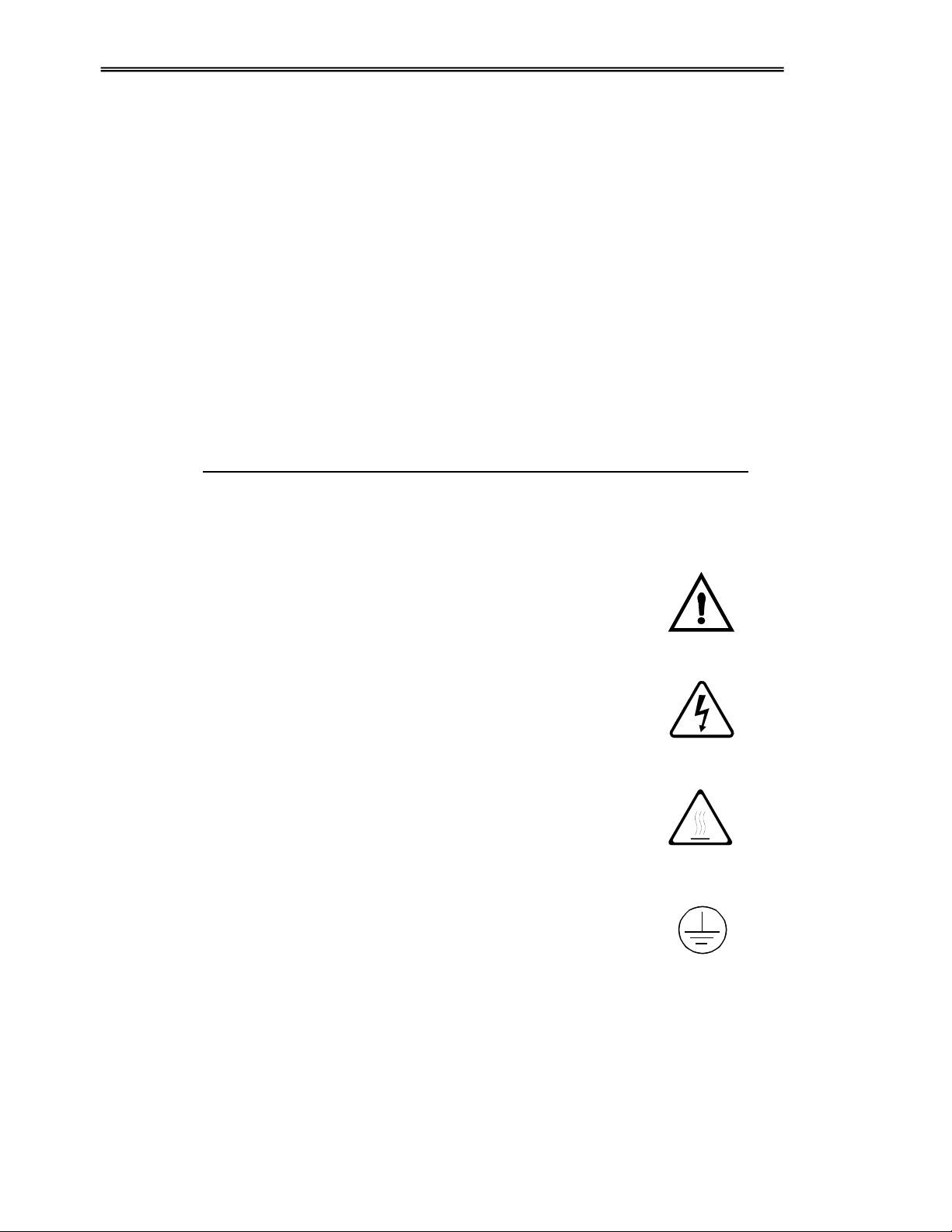
2.0 SAFETY WARNINGS & SYMBOLS