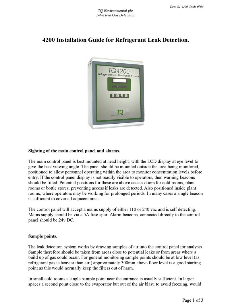
TQ Environmental TQ32 User manual

Tel: +44 (0) 1924 271013
Fax: +44 (0) 1924 262420
Email: sales@tqenv.com
Web: www.tqenv.com
TQ Environmental Limited
Silkwood Court
Wakefield
WF5 9TP
United Kingdom
OPERATING
MANUAL
TQ32
AREA
ALARM PANEL

TQ Environmental Limited
Page 2 of 28 14638PH6
Table of Contents
PROPRIETARY .................................................................................................................................................... 3
COPYRIGHT ........................................................................................................................................................ 3
WARNINGS, CAUTIONS AND NOTES ............................................................................................................... 3
SAFETY WARNINGS .......................................................................................................................................... 4
1.0 Introduction ....................................................................................................................................................... 5
1.1 Indication LED’s and Push Buttons .................................................................................................................... 6
2.0 Installation ......................................................................................................................................................... 7
2.1 Power Connection ............................................................................................................................................. 9
2.1 Sensor Connections ........................................................................................................................................... 9
2.3 Relay Connections ........................................................................................................................................... 10
2.4 Ethernet and Comms Connections .................................................................................................................. 11
3.1 Configuration Web Pages ................................................................................................................................ 14
3.2 Network Page .................................................................................................................................................. 17
3.3 System Page ..................................................................................................................................................... 19
3.4 Statistics Page .................................................................................................................................................. 20
3.5 Locations Page ................................................................................................................................................. 21
3.6 Relays Page ...................................................................................................................................................... 22
3.7 RS485 Serial Comms Page ............................................................................................................................... 24
4.0 Operation ......................................................................................................................................................... 25
5.0 Modbus ............................................................................................................................................................ 26
6.0 Technical Specification .................................................................................................................................... 27
List of Figures
FIGURE 1 - FRONT PANEL .......................................................................................................................................................... 6
FIGURE 2 - INSTALLATION SCHEMATIC ..................................................................................................................................... 7
FIGURE 3 - PANEL MOUNTING .................................................................................................................................................. 8
FIGURE 4 - POWER CONNECTION ............................................................................................................................................. 9
FIGURE 5 - SENSOR CONNECTION ............................................................................................................................................. 9
FIGURE 6 - RELAY CONNECTION .............................................................................................................................................. 10
FIGURE 7 - ETHERNET AND COMMS CONNECTIONS............................................................................................................... 11
FIGURE 8 - NETWORK CONNECTION DIALOG BOX .................................................................................................................. 12
FIGURE 9 - NETWORK CONNECTION PROPERTIES DIALOG BOX ............................................................................................. 13
FIGURE 10 - INTERNET PROTOCOL DIALOG BOX ..................................................................................................................... 13
FIGURE 11 - LOGIN DIALOG BOX ............................................................................................................................................. 14
FIGURE 12 - TQ32 AREA ALARM PANEL HOME PAGE ............................................................................................................. 15
FIGURE 13 - CONFIG LOGIN DIALOG BOX ............................................................................................................................... 16
FIGURE 14 - TQ32 AREA ALARM PANEL SETUP PAGE ............................................................................................................. 16
FIGURE 15 - NETWORK SETTINGS PAGE .................................................................................................................................. 17
FIGURE 16 - ADMIN PASSWORD PAGE .................................................................................................................................... 19
FIGURE 17 - CONFIG PASSWORD PAGE ................................................................................................................................... 19
FIGURE 18 - STATISTICS PAGE ................................................................................................................................................. 20
FIGURE 19 - LOCATIONS PAGE ................................................................................................................................................ 21
FIGURE 20 - CONFIG RELAYS PAGE .......................................................................................................................................... 22
FIGURE 21 - RELAY LOCATIONS PAGE ..................................................................................................................................... 23
FIGURE 22 - RS485 SERIAL COMMS PAGE ............................................................................................................................... 24

TQ Environmental Limited
Page 3 of 28 14638PH6
PROPRIETARY
No part of the hardware or documentation may be reproduced, transmitted, transcribed, stored in a retrieval
system, or translated into any language or computer language, in any form or by any means, without prior
written permission of TQ Environmental Limited.
While great efforts have been made to assure the accuracy and clarity of this document,
TQ Environmental Limited assumes no liability resulting from any omissions in this document, or from misuse of
the information obtained herein. The information in this document has been carefully checked and is believed
to be entirely reliable with all of the necessary information included.
TQ Environmental Limited reserves the right to make changes to any products described herein to improve
reliability, function, or design, and reserves the right to revise this document and make changes from time to
time in content hereof with no obligation to notify any persons of revisions or changes.
TQ Environmental Limited does not assume any liability arising out of the application or any use of any product
or circuit described herein; neither does it convey license under its patent rights or the rights of others.
COPYRIGHT
© TQ Environmental Limited 2016
This manual must not be copied or reproduced in part without the express written
permission of TQ Environmental Limited.
All information contained herein is subject to modification
WARNINGS, CAUTIONS AND NOTES
Warnings identify an operating or maintenance procedure, practice, condition,
or statement that, if not strictly followed, could result in death or injury to personnel.
Cautions, which appear elsewhere in this manual, identify an operating or
maintenance procedure, practice, condition, or statement that if not strictly followed could
result in equipment damage or serious impairment of system operation.
Notes highlight certain operating or maintenance conditions or statements that are
essential but not of known hazardous nature as indicated by Warnings and Cautions.
Warnings, Cautions and Notes are included throughout this manual, as required.
Additionally, this section contains important Warnings that may not be contained
elsewhere within this instruction manual.

TQ Environmental Limited
Page 4 of 28 14638PH6
SAFETY WARNINGS
FOR SAFETY REASONS, THE TQ32 AREA ALARM PANEL MUST BE
INSTALLED, OPERATED AND SERVICED BY QUALIFIED PERSONNEL ONLY.
READ AND UNDERSTAND THIS INSTRUCTION MANUAL COMPLETELY BEFORE
OPERATING THE TQ32.
THE OPERATION DESCRIBED IN THIS DOCUMENT IS THE INTENDED USE OF
THE TQ32.
TQ ENVIRONMENTAL LIMITED CANNOT BE HELD RESPONSIBLE IF THE TQ32
IS USED FOR ANY PURPOSE OTHER THAN THAT STATED. ANY OTHER USE OF
THE TQ32 WILL INVALIDATE ANY CERTIFICATES ISSUED.

TQ Environmental Limited
Page 5 of 28 14638PH6
1.0 Introduction
The TQ32 Area Alarm Panel enables the group monitoring of commonly used refrigerant
gases such as R410A in areas with air conditioning systems etc. using the TQ31 Refrigerant
sensor. It is designed to monitor a group of sensors in a specific area or floor and give an
indication if any of its sensors have gone into alarm.
The TQ32 Area Alarm Panel will provide a local visual and audible alarm indication when any
of its connected room sensors have entered the alarm state. It can also provide outputs for
remote monitoring, reception or security stations for example as well as providing a plant trip
signal.
There are 32 sensor inputs as standard, expandable to 64 inputs with the addition of an extra
Sensor Input Board. In addition, the TQ32 Area Alarm Panel has 2 optional RS485
communication channels. One channel is for an optional external relay board output that can
provides additional alarm relays if required. The other communication channel is for a
MODBUS Output to provide the status of the Alarm Inputs.

TQ Environmental Limited
Page 6 of 28 14638PH6
1.1 Indication LED’s and Push Buttons
The LED's on the TQ32 Area Alarm Panel are used to indicate the status of the Unit. There
are three LED’s and a 3 Digit 7-segment LED Display situated on the front of the Panel.
The System Healthy LED is a green LED and should normally be illuminated when power is
applied to the TQ32 Area Alarm Panel. The Refrigerant Alarm LED is a red LED and should
illuminate when an Alarm Input has entered an alarm condition. When the alarm condition has
been removed the Alarm LED will extinguish. The Multiple Alarm LED is a red LED and
should flash when more than one Alarm Input has entered an alarm condition. When the
alarm condition has been removed the Multiple Alarm LED will extinguish.
The 3 Digit 7-segment LED Display is used to show the location (room number) of the alarms.
This will alternate between rooms if more than one alarm is present. See configuration
section for allocating room numbers
3 Push buttons are provided on the front panel. The MUTE button accepts any alarms and
silences the audible alarm. The NEXT button allows the operator to view all rooms that may
be in alarm. The TEST button performs a basic test of the Alarm panel, LED’s and buzzer.
Note. Audible alarms from room sensors will only be silenced when any gas has
cleared and the alarm condition has gone.
Refrigerant
Alarm
Multiple
Alarm
System
Healty
Check
Room
TQ 32
Environmental
4 0 5
Figure 1 - Front Panel

TQ Environmental Limited
Page 7 of 28 14638PH6
2.0 Installation
A typical installation schematic is shown below
Figure 2 - Installation Schematic
Typical system Power Requirements.
TQ31 Room Sensors.
Each TQ31 Room sensor to be connected to the mains supply via electrical back box.
240v ac 0.1A load
Each TQ31 Room sensor to be connected to TQ32 Area Alarm Panel via 2 core, 0.5mm2 cable.
24v DC, alarm indication only, 0.1A DC
TQ32 Area Alarm Panels.
Each TQ32 Area Alarm panel to be connected to the mains supply via local fuse spur.
240v ac 0.5A load
If required each TQ32 Area Alarm panel to be connected to TQ34 Reception Indicator Panel via
3 core, 0.5mm2 cable ( 5 core if monitoring 2 floors ). 24v DC indication only, 0.1A DC
TQ35 Central Alarm Panel.
TQ35 Central Alarm Indicator Panel to be connected to the mains supply via local fuse spur.
240v ac 0.5A load

TQ Environmental Limited
Page 8 of 28 14638PH6
Each TQ32 Alarm panel needs to be securely wall mounted, ideally in a central location. The
TQ32 alarm panel will need to be connected to the mains supply.
Each room being monitored will need a TQ31 Refrigerant Room sensor fitted. These can be
mounted to 50mm deep, double back boxes and connected to the mains supply. See TQ31
manual for further instruction. A 2 core, 0.5 mm2 cable to signal any alarm condition needs to
be run back to the TQ32 Alarm panel from each room sensor.
If an optional Reception indicator panel is used to identify which floor or area is in alarm, then
a 3 core 0.5 mm2 cable needs to be run from the alarm panel relays to the reception panel.
343.00 mm
251.00 mm
Input cart #1 1-32
Input cart #2 33-64
Relay outputs 1-5
Cable entry at bottom
or through back of panel
Mains input
Connection
to control pcb
Figure 3 - Panel Mounting

TQ Environmental Limited
Page 9 of 28 14638PH6
2.1 Power Connection
WARNING 240VAC
Power for the TQ32 Area Alarm Panel is from a 100V-240V 50/60Hz AC supply. The green
power LED will illuminate on the front panel.
The power connection is via a fused terminal located
at the bottom right hand side, inside the alarm panel enclosure.
2.1 Sensor Connections
Each room sensor needs to be connected to the TQ32 Alarm Panel with a 2 core cable as
shown below. The input board terminals will accept wire sizes up to 0.5mm2.
Sensor inputs are connected in vertical pairs left to
right along the TQ32 input boards, as shown.
32 inputs on the top board with an additional 32 input
available from the lower board if fitted.
Each sensor pair should be connected to the TQ31
room sensors Common (C) and Normally Open (NO)
alarm contacts. See TQ31 manual for further
identification.
N E L
Figure 4 - Power Connection
Sensor 1
Sensor 2
Sensor 3 etc.
1 2 3
Figure 5 - Sensor Connection

TQ Environmental Limited
Page 10 of 28 14638PH6
2.3 Relay Connections
Five Common Alarm Relay contacts are available for remote indication on Connectors
CONN14 to CONN18.
(Normally Closed) contact is on Pin 1, (Common) contact is on Pin 2, and (Normally Open)
contact is on Pin 3.
The five relays can be typically used for:
1 x Fault
2 x Refrigerant Alarm - Plant Trip
2 x Refrigerant Alarm - Reception/Control Room
These contacts operate on the alarm state of the Alarm Panel’s inputs (TQ31 room sensors)
and are configurable via the internal web-server. These can be left as common relays
(default) or each of the 4 alarm relays can be allocated a group of sensors to further split the
alarms if required.
For each alarm relay RL1 (Fault)
plus RL2, 3, 4 & 5.
2 sets of output contacts are
available.
Each set of outputs has Common,
Normally Open and Normally Closed
volt free contact available as shown.
Figure 6 - Relay Connection

TQ Environmental Limited
Page 11 of 28 14638PH6
2.4 Ethernet and Comms Connections
The connections for Ethernet, RS485 MODBUS and TQ35 alarm panels can be found on the
pcb mounted on the rear of the enclosure door. See below for a typical connection schematic.
Please see Section 3. Initial setup, for instruction to connect to the web page.
See section 5, RS485 Serial Comms, for MODBUS connections
See the TQ35 manual for further information on comms connections and cable types to be
used for the alarm panel
Figure 7 - Ethernet and Comms Connections
Note:
Communications Cable conforming to the RS485 Standard should be used for the
installation of the TQ35 Central Alarm Panel or other RS485 MODBUS connection.
Specifically; 3 cores (1 twisted pair plus 1 single) screened with a cable Characteristic
Impedance, Z0, of 120Ω.

TQ Environmental Limited
Page 12 of 28 14638PH6
3.0 Initial Setup
The TQ32 Area Alarm Panel can be configured via a laptop connected to the Ethernet
connection of the TQ32. This can either be a “crossover” Ethernet cable or via an Ethernet
hub. The default TQ32 IP address is 192.168.34.150. To avoid conflict on the network, the
laptop should have a different IP address to that of the TQ32 Area Alarm Panel.
On the laptop, the IP address can be setup from the Control Panel. To access the Control
Panel, go to the Start menu and select Control Panel. When in the Control Panel select
Classic View, and select the following:
Control Panel -> Network and Sharing Center
Then click on the network connection in use. This will bring up a window as shown in Figure 7
below.
Figure 8 - Network Connection Dialog Box
Selecting the Properties tab will bring up the window as shown in Figure 9 below.

TQ Environmental Limited
Page 13 of 28 14638PH6
Figure 9 - Network Connection Properties Dialog Box
Figure 10 - Internet Protocol Dialog Box
When the screen is displayed,
type the settings into the box as
shown and click OK. The laptop
will then be able to communicate
with the TQ32 Area Alarm Panel
Web Server and allow it to be
configured.
Click on the Internet Protocol
Version 4 (TCP/IPv4) and then
click Properties. The dialog box
shown in Figure 10 will be
displayed.

TQ Environmental Limited
Page 14 of 28 14638PH6
3.1 Configuration Web Pages
The TQ32 Area Alarm Panel has an internal web-server that contains various web pages.
These web pages may be used for configuring various aspects of the TQ32 Area Alarm
Panel.
Configurable options include the following:
Network Settings
System Password
Input Room Number/Location allocation
Normally Energised or de-energised common relays
Input grouping allocation of common relays
RS485 Serial Communications Interfaces
To view these web pages, a web browser such as Mozilla Firefox, Chrome or Internet
Explorer is required. The TQ32 Area Alarm Panel is supplied with a factory set IP address of
192.168.34.150. To view the default web page in the TQ32 Area Alarm Panel, start the web
browser and type 192.168.34.150 into the address line of the browser window. A username
and password dialog box will appear as shown in Figure 11 below:
Figure 11 - Login Dialog Box
The default username is admin and the default password is left blank. The Home Page of the
TQ32 Area Alarm Panel will now be displayed in the browser window as shown in Figure 12.

TQ Environmental Limited
Page 15 of 28 14638PH6
Figure 12 - TQ32 Area Alarm Panel Home Page
If no web page is displayed, go back to testing the network connection to the TQ32 Area
Alarm Panel by using the ping command in the Command Prompt desktop app.
The sensor alarm status is automatically refreshed every five seconds; however, the user
may manually refresh this page by clicking on the Refresh button. Figure 12 shown above
indicates that the sensor in Room 105 is in alarm.
To enter the Configuration pages the user may click on the Gear icon at the top right of the
screen. This will prompt the user to enter the config password as shown in Figure 13.

TQ Environmental Limited
Page 16 of 28 14638PH6
Figure 13 - Config Login Dialog Box
The default username is config and the default password is 1234.
The Setup Page of the TQ32 Area Alarm Panel will now be displayed in the browser window
as shown in Figure 14 below:
Figure 14 - TQ32 Area Alarm Panel Setup page

TQ Environmental Limited
Page 17 of 28 14638PH6
3.2 Network Page
This web page allows you to change the network properties of the TQ32 Area Alarm Panel,
including the IP address, Subnet Mask, Default Gateway, Primary and Secondary DNS
Servers and the Unit Station Number for MODBUS purposes. When you click on the link then
the web page shown in Figure 15 is displayed.
Figure 15 - Network Settings Page
IP Address:
The new IP address can be entered into the web page dialog box as shown above. After this
has been done, if no other changes are to be made, the user must click the Change button to
send the values to the TQ32 Area Alarm Panel. The new IP address will be effective
immediately. After the IP address has been changed, you need to also change the host IP
address in your internet browser to re-connect to the TQ32 Area Alarm Panel. Make changes
with care or you may permanently lose a connection until the next hardware reset. Clicking
the Back button will take the user back to the Setup Page.
Subnet Mask:
In computer networks, a subnetwork or subnet is a range of logical addresses within the
address space that is assigned to an organisation. The subnet mask is used to inform the
TQ32 Area Alarm Panel that it must send its replies to the gateway if the IP address of the PC
is on a different network. When the subnet mask is set to “0.0.0.0” then it is effectively
disabled and the Default Gateway is not used. A typical subnet mask would be
“255.255.255.0”.
Default Gateway:
A Default Gateway is a node (a router) on a computer network that serves as an access point
to another network. In enterprises, however, the gateway is the computer that routes the
traffic from a PC to the outside network that is serving the web pages. It is only necessary to
configure the default gateway IP address if the PC that is accessing the TQ32 Area Alarm
Panel is on a different network.

TQ Environmental Limited
Page 18 of 28 14638PH6
Primary/Secondary DNS Server:
The Domain Name System (DNS) is a hierarchical distributed naming system for computers,
services, or any resource connected to the internet or private network. It translates domain
names meaningful to humans into the numerical identifiers associated with networking
equipment for the purpose of locating and addressing these devices worldwide.
Unit Station Number:
The MODBUS ‘slave address’ field usually used on MODBUS Serial Line is used to
communicate via devices on the MODBUS network. This field is a unique address on the
MODBUS network in use.

TQ Environmental Limited
Page 19 of 28 14638PH6
3.3 System Page
This web page allows the TQ32 Area Alarm Panel passwords to be changed. Hovering the
mouse over the System link on the Setup Page displays two additional links; admin
Password and config Password. Clicking the admin Password link will display the web page
shown in Figure 16.
Figure 16 - admin Password Page
The user must click the Change button to send the values to the TQ32 Area Alarm Panel.
Clicking the Back button will take the user back to the Setup Page.
Clicking the config Password link will display the web page shown in Figure 17 below.
Figure 17 - config Password Page

TQ Environmental Limited
Page 20 of 28 14638PH6
3.4 Statistics Page
This web page shows the network connection status of the TQ32 Area Alarm Panel. This may
be useful for network diagnostic purposes. The web page shown in Figure 18 is displayed
when the link on the Setup page is clicked.
Figure 18 - Statistics Page
This page will be automatically refreshed every five seconds, or the user may manually
refresh the page by clicking the Refresh button.
Table of contents
Other TQ Environmental Measuring Instrument manuals
Popular Measuring Instrument manuals by other brands
Niigata seiki
Niigata seiki WCDI-50 instruction manual

PCB Piezotronics
PCB Piezotronics TLC356A14 Installation and operating manual
Desco
Desco 19430 Installation, operation and maintenance
CESVA
CESVA DC112 user manual
Trend Micro
Trend Micro Deep Discovery Inspector 1000 quick start guide

Kistler
Kistler KiTorq 4542A Series instruction manual
