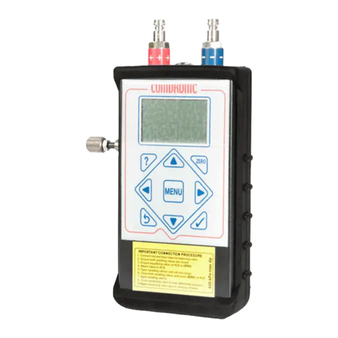
Comdronic AC7 User manual

www.comdronic.co.uk
AC7 Operating Instructions
Contents
Health and Safety 1
Statement of Conformity 1
Measurement Range & Accuracy 1
Contact Us 1
Description of AC7 2
Connection Procedure 3
Disconnection Procedure 3
Menu Map 4
Display Menu 5
Main Menu 8
Units Menu 11
Damping Menu 12
Advanced Menu 13
Quick-Valve Storing Function 15
Appendices
Glycol / Water Specific Gravity Chart A1
Recommended User Maintenance Procedures A2

www.comdronic.co.uk

www.comdronic.co.uk
Health and Safety
Comdronic Ltd takes every reasonable precaution to ensure that AC7 Electronic Commissioning Meters are
designed, constructed, calibrated and tested for safe and trouble-free operation when used in accordance with
these operating instructions.
It is the user’s responsibility to be aware of the general hazards associated with the systems being
commissioned (e.g. high pressures; high / low temperatures; the presence of flushing / cleaning / antifreeze
agents; etc.) and to use appropriate personal protective equipment / clothing for the hazards potentially
present.
Statement of Conformity
This is to certify that the Comdronic AC7 Electronic Commissioning Meter is manufactured in the UK and
conforms to the published specification. It is CE Marked in accordance with the relevant EU legislation.
Measurement Range & Accuracy
Accuracy
(% of reading):
+/- 1% of reading or +/- 0.20 kPa
(whichever is greater)
Max Allowable
Static Pressure:
20 bar
Measurement
Range:
1.0 kPa to 800 kPa
Factory calibration is carried out, in controlled conditions, using reference equipment which has been
independently calibrated to UKAS standards.
Generally, it is recommended that AC7 handsets are serviced and calibrated annually –please ‘Contact Us’ for
further information. However, this is not a fixed period and shorter service intervals may be necessary for
extremely high-use meters or for meters which are regularly used on very dirty systems or on systems that
contain high concentrations of cleaning agents / treatments.
Between services, there are some simple maintenance procedures which can be performed to help prolong
the accuracy and performance of the AC7 –please refer to Appendix II for further information.
Contact Us
For all sales, technical or troubleshooting enquiries:
Email: enquiries@comdronic.co.uk
Tel: +44 (0) 1473 715589
Address: Unit 7 Alpha Terrace, West Road, Ipswich, Suffolk, IP3 9FD, UK
1

www.comdronic.co.uk
Description of AC7
Press & hold the MENU button to switch the AC7 ‘ON’.
Connect the BLUE
connection tube
to this connector.
Securing ring. Use the
lanyard supplied to suspend
the AC7 from adjacent
pipework (or similar) while
taking readings.
Press to set a zero
datum before taking a
measurement (see
opposite).
Press to enter menu
screens.
Press MENU again for
language options.
Use the ▲ ► ▼ ◄ buttons
for menu navigation and to
enter numerical data.
Press to accept
menu selections
and screen entries.
Connect the RED
connection tube
to this connector.
Internal strainers protect the
sensor-unit from small dirt
particles. These are service parts.
Note: blocked strainers will slow
performance and reduce
accuracy.
Equalising valve.
Press to cancel an entry or to
return to a previous screen.
Also use to switch the AC7 ‘OFF’.
2
9V Battery
1 x Alkaline 9V PP3 battery.
Battery access at rear.
Typical effective operating
time = up to 20 hours.
ENGLISH
ESPANOL
FRANCAIS
ITALIANO
NORSK
SVENSKA
Select Language
Use the ▲▼ buttons to select a language.
Press OK to accept.
Key
Throughout these instructions, there are
two abbreviations used for ‘differential
pressure’ as follows:
Δp is used in the body text.
DP is used in the screen images.
Press for context-
sensitive help.

www.comdronic.co.uk
The AC7 handset is supplied in a lightweight carrycase with the following accessories:
A pair of connection tubes, complete with manually-operated isolation valves.
A pair of angle-pattern Binder-style connection adaptors with 2.8mm diameter needles.
A pair of angle-pattern Binder-style connection adaptors with 2.0mm diameter needles.
A set of hex keys (3mm, 4mm & 5mm) and a screwdriver.
A lanyard to suspend the handset from pipework whilst in use.
A strainer maintenance kit.
A spare battery.
Operating Instructions, a Quick-Start Guide and a Factory Calibration Certificate.
Connection Procedure
Note: each connection tube is fitted with an isolating valve and it is a matter of user-preference whether
the tubes are used with the isolating valves adjacent to the
AC7
or, alternatively, adjacent to the subject
measuring valve / device.
1.
Select the correct connection adaptors for the valve / device being measured and attach them to
the connection tubes.
2.
Ensure that both isolating valves on the connection tubes are in the
CLOSED
position.
3. Attach the connection adaptor on the RED connection tube to the high-pressure (upstream) test point
on the subject measuring valve / device.
4. Attach the connection adaptor on the BLUE connection tube to the low-pressure (downstream) test
point on the subject measuring valve / device.
5. Ensure that the equalising valve on the AC7 is OPEN.
6. Attach the free ends of the RED and BLUE connection tubes to the colour-coded connection points on
the AC7.
7. OPEN the isolating valves on the connection tubes to allow the line fluid to purge any air from inside
the tubes.*
8. CLOSE the isolating valves on the connection tubes.
9. Find a safe and static position for the AC7.**
10. Switch the AC7 ‘ON’ and press the ZERO button to set the datum at zero.***
11. OPEN the isolating valves on the connection tubes and CLOSE the equalising valve on the AC7.
12. The AC7 will now be reading Δp.
*
If the
Δp
across the valve / device is low, the purging process will be slow due to the internal resistance
of the
AC7
.
**
The
AC7
is very sensitive and readings will be affected if the position of the handset is moved or
adjusted after a datum has been set. A lanyard is provided and can be used to suspend the
AC7
from
adjacent pipework, as appropriate.
***If the AC7 is being subjected to an extreme change of temperature at this point, the datum may drift from
zero as the internal temperature of the meter changes and, in these circumstances, it will be necessary to
repeat this step until the internal temperature has stabilised and a zero datum is maintained.
Disconnection Procedure
1. OPEN the equalising valve on the AC7.
2. CLOSE both isolating valves on the connection tubes.
3. Disconnect the tubes from both the AC7 and the valve / device.
3

www.comdronic.co.uk
Menu Map
The AC7 has five menus for ease of use:
MAIN
MENU
►
UNITS
MENU
►
DISPLAY
MENU
►
DAMPING
MENU
►
ADVANCED
MENU
◄
◄
◄
◄
Select A
Valve
Select DP
Units
DP And
Flow
Change
Update
Time
Flow Alerts
▼▲
▼▲
▼▲
▼▲
▼▲
Valve
Setting
Select Flow
Units
Advanced
Change
Sample
Time
Backlight
Timer
▼▲
▼▲
▼▲
Specific
Gravity
DP Only
Auto-off
Timer
▼▲
▼▲
▼▲
Design
Flow
Flow Only
On-Screen
Size Units
▼▲
▼▲
▼▲
Target
Flow %
About
Pipe ID
▼▲
Change Kvs
Note: menu options shown in red will require numerical data to be entered and this is achieved using the
buttons on the keypad. The default starting digit is always zero –then use the ▲▼buttons to change the
value. Use the ►button to add a digit and the ◄button to remove a digit. If a decimal point is required, press
the ▼button when the zero digit is showing. To enter a negative number, press the ZERO button before any
number is added. The following example shows how a user would set a Design Flow of 1.05:
MENU enters the Main Menu
▼▼▼ moves the cursor down to the Design Flow option
OK accepts the Design Flow option
▲changes the value of the first column to 1
►selects the next column
▼selects a decimal point
►selects the next column
▲▲▲▲▲ changes the digit to 5
OK accepts the on-screen value of 1.05
EXIT returns to the chosen display screen
4

www.comdronic.co.uk
Display Menu
There are four different display formats available for the AC7. The most appropriate format will depend on the
type of valve / device being measured and the commissioning method being applied. The four display formats
are described below but, first, it is important to explain some automatic alerts
which may appear on any of
these screens as and when certain circumstances exist as follows:
*The pressure sensor within the AC7 ceases to compensate for temperature at temperatures above 50°C.
However, as long as purge times are kept to a minimum, the temperature of the fluid within the meter is
usually closer to ambient than the temperature of the line fluid.
The DP And Flow Display is suitable for most general commissioning purposes. Fig. 1 shows an example of
displayed data when a fixed orifice valve has been selected and fig. 2 shows an example of displayed data
when an automatic balancing valve has been selected.
Fig. 1
5
Schematic of the
selected valve.
Kvs of the
selected valve.
Details of the
selected valve.
Derived Flow.
Calculated by the AC7
using the measured Δp
and the Kvs.
Measured Δp.
5.30
Crane Fixed D931 15mm
KPa
l / s
0.141
Kvs
2.20
ZERO DP
SG
TEMP HIGH
This symbol will show when the
remaining battery power drops
below 8.0 volts. This is for
INFORMATION ONLY as there is
still plenty of run-time available.
The ZERO button will need to be
pressed to set a datum (see
Connection Procedure on page 3)
before readings can be taken.
Specific Gravity is not set
to 1.0, so readings are
currently being auto-
corrected for SG.
The temperature of the fluid
inside the handset is too high
for readings to be
temperature-compensated.*
Remaining battery power
has dropped below 6.5 volts
and is too low for the AC7
to function. Action: FIT A
NEW BATTERY.
This symbol will show when the
remaining battery power drops
below 7.5 volts. Action: ensure
that a replacement battery is
on-hand.

www.comdronic.co.uk
Fig. 2
*If the measured Δp reaches the design Δp for the selected valve, the flow status message will be FLOW OK.
However, if the design Δp is not met the flow status message will be LOW FLOW.
The Advanced Display can show more complex commissioning data and it may be preferred to the DP And
Flow Display if automatic balancing valves are being measured or if a system of proportional balancing is being
adopted. Fig. 3 shows an example of displayed data when a variable orifice valve has been selected and fig. 4
shows an example of displayed data when an externally adjustable automatic balancing valve has been
selected.
Fig. 3
**These are iterative processes due to the unknown valve authority in the circuit and so 2-3 attempts may be
required to achieve the desired reading. Please also note that in conjunction with pressing the ◄or ►button
on the AC7, the physical handwheel setting of the valve will also need to be changed to match the new value.
6
Current cartridge
setting.
Flow status
message.*
Details of the
selected valve.
Derived Flow.
Measured Δp.
20.48
FlowCon Green Green.0 15-25mm
KPa
l / s
0.210
FLOW
OK
l / s
0.210
5.00
Design Flow for
this valve at this
setting.
Press the ▲
button to change
valve setting.
Current
handwheel setting.
Kvs of the selected
valve at the current
handwheel setting.
Derived Flow as a % of the
Target Flow. If no Target
Flow has been entered,
“---“ is displayed.
Derived Flow.
Measured Δp.
5.30
Crane Variable D930/DM930 15mm
KPa
l / s
0.256
DESIGN
4.00 Kvs
4.00
101%
103%
TARGET
3.82
3.95
Press the ▲button to MANUALLY
change the handwheel setting that
the AC7 is using.
Derived Flow as a % of the
Design Flow. If no Design
Flow has been entered,
“---“ is displayed.
Predictive handwheel
setting to achieve the
Design Flow.
Use the ◄button to
AUTOMATICALLY
change the ‘Current
Handwheel Setting’
being used by the AC7
to this value.**
Predictive handwheel
setting to achieve the
Target Flow.
Use the ►button to
AUTOMATICALLY
change the ‘Current
Handwheel Setting’
being used by the AC7
to this value.**

www.comdronic.co.uk
Fig. 4
*The Design Flow for any automatic balancing valve will be achieved if the Δp across the valve reaches (or
exceeds) the design value.
If the Design
Δp
is met, the displayed message will be
FLOW OK
.
If the Design
Δp
is not met, the displayed message will be
LOW FLOW
.
The DP Only Display (shown in fig. 5) is the simplest option available and may be preferred when the AC7 is
being used as a simple manometer.
Fig. 5
The Flow Only Display (shown in fig. 6) would normally only be the preferred display screen when fluid
velocities are being measured for the purposes of system flushing.
Fig. 6
7
Up arrow indicates
that the Δp must be
increased to achieve
the Design Flow.
Approx.
actual flow.
Design Flow for this
valve at this setting.
Δp required to
achieve Design Flow.
Current valve
setting.
FlowCon Green Green.0 15-25mm
LOW
FLOW
0.210
l / s
5.00
14.50 KPa
0.200
l / s
16.00
1.50
Down arrow indicates
that the Δp is
unnecessarily high.
Measured Δp.
Difference between Measured
Δp and Design Δp.
Flow status
message.*
Use the ▲button to edit
the ‘Current Valve Setting’.
(▲not shown if valve is a fixed setting type).
Chevrons in the inlet
pipe indicate that the
flow is greater than zero.
Chevrons will show in
the outlet pipe when
Design Flow is achieved.
| KPa
4.27
Measured Δp.
Units of measure.
Kvs= 2.3 | m/s
1.37
Calculated Fluid
Velocity.
Units of measure.
16.1mm
Internal Pipe Diameter
being used to calculate
the fluid velocity.

www.comdronic.co.uk
The ‘About’ menu option (shown in fig. 7) gives the unique serial number of the AC7 (please quote this in any
correspondence with Comdronic) plus the installed firmware version.
Fig. 7
Main Menu
The Main Menu is concerned with the various selections / parameters that a user may wish to enter
depending on the valve / device being measured and the commissioning techniques being utilised.
The performance characteristics of over 5,000 valves –from 70+ manufacturers / brands –are pre-
programmed into the AC7 and this data is automatically updated whenever an AC7 is serviced by Comdronic.
Note: w
hilst every effort is made to ensure that
stored valve data is correct, valve manufacturers
invariably reserve the right to
modify their products, without notice, and so Comdronic cannot be held
responsible for any inaccuracies or
omissions
.
Fig. 8
Make selections for all four parameters (i.e. Manufacturer, Type, Fig. No.& Size) before pressing OK to accept
them.
8
CRANE
Variable
D902
15mm
Manufacturer / Brand.
Valve Type
e.g. Fixed, Variable,
PICV, etc.
Valve Fig. No.
Valve Size.
Use the ◄► buttons
to scroll through the
available options for
each parameter.
Use the ▲▼ buttons
to select a parameter.
Firmware version.
Unique serial number.
SNO-0123 (A29D) 6.03.210
COMDRONIC AC7
comdronic.co.uk

www.comdronic.co.uk
When variable orifice valves or adjustable automatic balancing valves are being measured, the handwheel
position / cartridge setting must be entered so that the correct flow data is used for the
derivation of
flow.
Fig. 9
Once the new value is correct on the screen, press OK to accept it. Or, press EXIT to exit the screen and retain
the current setting.
*The minimum handwheel position shown ensures that the valve maintains reasonable accuracy.
This menu option allows the user to enter the SG of the line fluid. Typically, this would be necessary when
glycol (or similar) is present in the system. Please refer to Appendix I for further information.
Fig. 10
Once the new value is correct on the screen, press OK to accept it. Or, press EXIT to exit the screen and retain
the current setting.
Note: while SG is set to a value other than 1.0, “SG” will show at the top of the chosen display screen as a
reminder to the user that readings are being subjected to a correction. It is strongly recommended that
users regularly check that the set value for SG is appropriate for the system being commissioned.
9
= 4
Use the ►button
to add a digit.
Current setting.
Min = 1 Max = 4
2 .4
Use the ◄button
to remove a digit.
Use the ▲▼ buttons
to increase or
decrease a value.
Min.*& Max.
usable settings for
the selected valve.
= 1
Use the ►button
to add a digit.
Current setting.
Enter SG
1 .01 7
Use the ◄button
to remove a digit.
Use the ▲▼ buttons
to increase or
decrease a value.

www.comdronic.co.uk
The Design Flow for the selected valve can be entered / edited in this screen. When a value is entered, the
derived flow will be calculated as a percentage of the Design Flow and this will be displayed on the Advanced
Display in the Design Flow box.
Fig. 11
Once the new value is correct on the screen, press OK to accept it. Or, press EXIT to exit the screen and retain
the current setting.
The Target Flow % for the selected valve can be entered / edited in this screen. When a value is entered, it will
be displayed on the Advanced Display in the Target Flow box. Target Flow must be entered as a percentage
and is generally required when carrying out advanced proportional balancing. Typically, the value used will be
the same as the calculated Design Flow percentage on the index circuit. Balancing to 100% target on
subsequent valves will ensure that valves adjacent to the index valve are ‘balanced’.
Fig. 12
Once the new value is correct on the screen, press OK to accept it. Or, press EXIT to exit the screen and retain
the current setting.
10
= 10.2 l/s
Use the ►button
to add a digit.
Current setting.
Enter Design Flow
10 .8
Use the ◄button
to remove a digit.
Use the ▲▼ buttons
to increase or
decrease a value.
= 94%
Use the ►button
to add a digit.
Current setting.
Enter Target Flow %
9 7
Use the ◄button
to remove a digit.
Use the ▲▼ buttons
to increase or
decrease a value.

www.comdronic.co.uk
If the valve / device is not listed in the AC7’s database, this menu option enables the user to manually enter a
Kvs value so that a derived flow can still be calculated by the AC7.
Fig. 13
Once the new value is correct on the screen, press OK to accept it. Or, press EXIT to exit the screen and retain
the current setting.
Units Menu
Default = kPa
Available options are kPa, psi, bar, cmH2O,
IWGA (inches water gauge), Ft HD (feet head) or Pa.
Fig. 14
Default = l/s
Available flow options are l/s, l/m, l/h, USGPM, UKGPM, m3/h, m3/m or m3/s.
Available velocity options are m/s or f/s.
Fig. 15
11
= 2.2 Kvs
Use the ►button
to add a digit.
Current setting.
Enter New Kvs
2 .3
Use the ◄button
to remove a digit.
Use the ▲▼ buttons
to increase or
decrease a value.
Pa x 0.000145
Conversion
factor from
pascals.
Select DP Unit
0.0
Decimal place
format for the
selected units.
Use the ◄► buttons
to scroll through the
available options.
Press OK to accept.
PSI
l/s x 60
Conversion
factor from
litres per second.
setting.
Select Flow Unit
0.00
Decimal place
format for the
selected units.
l/m
Use the ◄► buttons
to scroll through the
available options.
Press OK to accept.

www.comdronic.co.uk
Damping Menu
Default = 1.00 SEC
This screen allows the user to adjust the apparent sensitivity of the AC7 by changing the time delay between
each screen update from a minimum value of 0.1 SEC to a maximum value of 2.55 SEC. A long Update Time may
be advisable on an unstable system in order to give a steadier reading.
Fig. 16
Once the new value is correct on the screen, press OK to accept it. Or, press EXIT to exit the screen and retain
the current setting.
Default = 3.0 SEC
This screen allows the user to adjust the period of time over which readings are averaged, from a minimum
value of 0.6 SEC to a maximum value of 11.0 SEC. Increasing the Sample Time will make the screen appear to
update less frequently, but with a more stable reading.
Fig. 17
Once the new value is correct on the screen, press OK to accept it. Or, press EXIT to exit the screen and retain
the current setting.
12
Update Time
2.00 SEC
Use the ▲▼
buttons for coarse
adjustment.
SAMPLE TIME
3.0 SEC
New Update Time.
Press OK to accept.
Use the ◄►
buttons for fine
adjustment.
Current Sample
Time is also shown
for information.
Sample Time
5.0 SEC
Use the ▲▼
buttons for coarse
adjustment.
New Sample Time.
Press OK to accept.
Use the ◄►
buttons for fine
adjustment.

www.comdronic.co.uk
Advanced Menu
Default = Disabled
There are two Flow Alerts: HIGH FLOW*and LOW FLOW and these relate to the flow through the selected
valve.
Fig. 18
*For static balancing valves, HIGH FLOW conditions would normally mean that the flow through the device is in
excess of recommended maximum flows as quoted in BS7350. For automatic balancing valves, HIGH FLOW
conditions would normally mean that the maximum working Δp for the device has been exceeded. The
presence of the HIGH FLOW alert on the screen will almost certainly be accompanied by significant system
noise.
Note: if Flow Alerts are Enabled when working on an unstable system, the displayed alert may change, quite
frequently, between the HIGH / LOW options and this may only serve to
impede –rather than assist –the
commissioning process. Hence, it is strongly recommended that Flow Alerts remain Disabled when work
is being carried out on an unstable system, or on a system that has little regulation.
Default = 5 min
The Backlight Timer sets the period of time after which the backlight will turn off after a period of inactivity.
A short time will preserve battery life.
Fig. 19
13
High / Low Flow Alerts
Enabled
Use the ▲▼
buttons to move
between the
settings.
Press OK to accept.
Disabled
Select Light-On Time
5 min
Use the ▲▼
buttons to move
between the
settings.
Press OK to accept.
10 min
1 min
Always On

www.comdronic.co.uk
Default = 5 min
The Auto-Off Timer sets the period of time after which the AC7 will turn ‘OFF’ after a period of inactivity.
A short time will preserve battery life.
Fig. 20
Default = mm
This menu option allows the user to specify the preferred units for viewing and selecting valve sizes.
Fig. 21
This is the internal pipe diameter of the pipework that the target measuring valve / device is installed in and it
is used by the AC7 to establish the velocity in the pipe for flushing purposes. Velocity units are available (m/s
or f/s) and these can be selected in the Units Menu. A valve will need to be selected (see page 8) in order for
this feature to be used.
Fig. 22
Once the new value is correct on the screen, press OK to accept it. Or, press EXIT to exit the screen and retain
the current setting.
14
Select Auto-Off Time
5 min
Use the ▲▼
buttons to move
between the
settings.
Press OK to accept.
10 min
1 min
Always On
View Size As
mm
Use the ▲▼
buttons to move
between the
settings.
Press OK to accept.
Inches
= 16.1 mm
Use the ►button
to add a digit.
Current setting.
Internal Pipe Diameter
21 .6
Use the ◄button
to remove a digit.
Use the ▲▼ buttons
to increase or
decrease a value.

www.comdronic.co.uk
Quick-Valve Storing Function
Quick-Valve allows the user to quickly save commissioning data for individual valves to the AC7’s on-board
memory. Within Quick-Valve, there are 1,000 storage locations and these are arranged in 50 groups of 20
valves.
Quick-Valve can be accessed from any of the display screens (i.e. DP And Flow Display, Advanced Display, DP
Only Display or Flow Only Display). Simply press OK whilst in any of these screens and the last-viewed storage
location will be shown on the screen. At the first time of use, Gp. 1, No. 1 will be the displayed storage
location.
Once Quick-Valve has been accessed, the storage locations are navigable by using the ▲▼ buttons to change
the Group No. and the ◄► buttons to change the Valve No. As the various storage locations are viewed, the
on-screen display will change depending on whether the location is ‘empty’or whether it already contains
stored data. Examples of these screens and the further feature options are shown below.
Note: even when a user is within the Quick-Valve screens, the AC7 will be continuing to take readings (even if
the AC7 is not connected to a system it will still be taking a reading!) and it may have a valve selected or a
manual Kvs entered. Also, values for Target Flow and / or Design Flow may have been entered. For the
purposes of this section, this data will be referred to as the ‘Live Data’.
Example 1 –If the selected storage location already contains data, the stored data will be shown:
Fig. 23
With the above screen in view, pressing the MENU button will display the following options:
Fig. 24
15
5.30 KPa
Crane Variable D930/DM930 15mm
0.256 l/s
DESIGN 103%
0.249
TARGET 101%
4.0
Gp. 1 No. 1
DESIGN FLOW
TARGET FLOW
102%
Gp. 1 No. 1
►SAVE ‘LIVE’ DATA TO LOCATION
Press the ▲ button
to clear (delete!) the
stored data from
this location.
Press the ◄button to
make the data in this
location the ‘Live Data’
for the AC7.
◄MAKE STORED DATA ‘LIVE’
▲CLEAR DATA FROM LOCATION
Press EXIT to take no
action and revert to
previous screen.
Press the ►button to
save (overwrite!) the data
currently stored in this
location with the
‘Live Data’.
EXIT

www.comdronic.co.uk
Example 2 –If the selected storage location is ‘empty’, the following screen will be displayed:
Fig. 25
With the above screen in view, pressing the MENU button will display the following options:
Fig. 26
Gp. 6 No. 9
Δp and Flow from the
‘Live Data’.
5.30 KPa
MENU
0.256 l/s
Use the ▲▼
buttons to select a
Group No.
Use the ◄►
buttons to select a
Valve No.
Currently selected
Group No. & Valve No.
16
Gp. 6 No. 9
►SAVE ‘LIVE’ DATA TO LOCATION
Press EXIT to take no
action and revert to
previous screen.
Press the ►button
to save the ‘Live Data’
to this location.
EXIT

www.comdronic.co.uk
Appendix I
Glycol / Water Specific Gravity Chart
% Glycol Additive
Temperature
O
C
0
10
20
30
40
50
60
70
80
90
100
80
0.991
1.003
1.017
1.026
1.036
1.046
1.054
1.062
1.068
70
0.990
1.000
1.010
1.023
1.034
1.042
1.053
1.062
1.069
1.075
60
0.995
1.007
1.017
1.030
1.041
1.050
1.060
1.070
1.076
1.083
50
1.000
1.013
1.023
1.035
1.048
1.057
1.067
1.077
1.084
1.090
40
0.990
1.004
1.018
1.029
1.042
1.054
1.064
1.074
1.085
1.091
1.098
30
0.996
1.007
1.022
1.034
1.047
1.059
1.070
1.080
1.092
1.099
1.105
20
0.999
1.010
1.026
1.038
1.052
1.065
1.076
1.088
1.099
1.106
1.114
10
1.000
1.013
1.028
1.042
1.056
1.070
1.082
1.094
1.105
1.113
1.120
0
1.000
1.015
1.029
1.045
1.061
1.075
1.088
1.100
1.112
1.120
1.128
-10
1.048
1.065
1.079
1.092
1.107
1.118
1.127
1.135
-20
1.068
1.083
1.097
1.113
1.124
1.133
1.136
-30
1.087
1.100
1.118
1.128
1.137
1.137
-40
1.102
1.122
1.133
1.138
1.138
E&OE
A1

www.comdronic.co.uk
Appendix II
Recommended User Maintenance Procedures
Pressure Sensor Flushing
The pressure sensor within the AC7 is protected from the majority of system-dirt by the presence of a strainer
in each of the Red and Blue connection ports on the top of the unit. These strainers have been carefully
selected and will prevent all but the smallest of dirt particles from entering the sensor-unit. They are vital for
maintaining the proper performance of the AC7.
Over time, however, there may be a build-up of tiny dirt particles within the sensor-unit and if this is allowed
to continue the performance of the AC7 may become affected in two ways:
A. Readings may be significantly less than the true value, and / or
B. On-screen readings may change very slowly when adjustments are made to the balancing valve.
Regularly performing a simple flush will help to reduce any build-up of dirt within the sensor-unit:
1. Ensure that the equalising valve on the AC7 is fully OPEN.
2. Hold the AC7 upside down and connect a cool, clean, water supply to the Blue connector and allow
the water to flow out of the Red connector. This is the back-flush and should always be done first.
3. Whilst keeping the AC7 upside down, disconnect the water supply from the Blue connector and
reattach it to the Red connector and allow water to flow out of the Blue connector. This is the
forward-flush.
In addition to performing simple flushes, if the AC7 is regularly used on extremely dirty systems it may also be
necessary to periodically perform an advanced flush. An advanced flush is the same basic process as a simple
flush but it is performed with the strainers temporarily removed (see strainer removal instructions opposite).
During an advanced flush, it is advisable to clean the strainers in a soapy solution and then flush them with a
pressurised air / water source. However, if the strainers are in very poor condition it may be necessary to
replace them with new (spare part order code = HS-STR-P).
If an AC7 continues to read incorrectly even after an advanced flush and strainer change, please ‘Contact Us’
for further advice.
Hose Maintenance
The connection tubes supplied with the AC7 are fitted with snap-connectors on both ends. Over time, these
snap-connectors may become a bit stiff to operate as system dirt accumulates in the ‘snapping’ mechanism
and continued use may result in damage to the AC7. To avoid this, the regular application of a small amount of
multi-purpose grease in each of the snap-connectors will help to keep them in good working order.
A2
Table of contents
Other Comdronic Measuring Instrument manuals
Popular Measuring Instrument manuals by other brands

Eilon Engineering
Eilon Engineering RON 2501 User guide and instruction manual

Dwyer Instruments
Dwyer Instruments TUF series Specifications-installation and operating instructions

Kobold
Kobold Heinrichs HPC Supplementary Operating Manual

Anritsu
Anritsu 56100A Operation and programming manual

R&S
R&S FSW Series user manual

Velleman
Velleman PersonalScope HPS5 manual