Trace Acoustic TAG1 User manual

OPERATING
INSTRUCTIONS
TAG1
ACOUSTIC
GRAPHIC EQUALISER
TAP1
ACOUSTIC
PREAMP
TAC1
ACOUSTIC
COMPRESSOR
PEDAL
SERIES

The TAG1 pedal can provide a wide range of EQ that is easily and instantly
adjustable from a graphic equaliser specifically designed to suit acoustic
instruments, provide two preshaped instant sounds, provide any combination of
the graphic and preshapes, provide a switchable volume boost, and can function in
the effects loop or on the front end of any amplification system.
We at TRACE ELLIOT consider that one battery of 9 volts does not give sufficient
headroom in the circuitry for the peaks in the signal from your instrument
especially with the massive boost and cut available in the equalisation section, so
as not to compromise the signal integrity the TAG1 pedal uses two 9 volt batteries
to give an internal power supply of 18 volts.
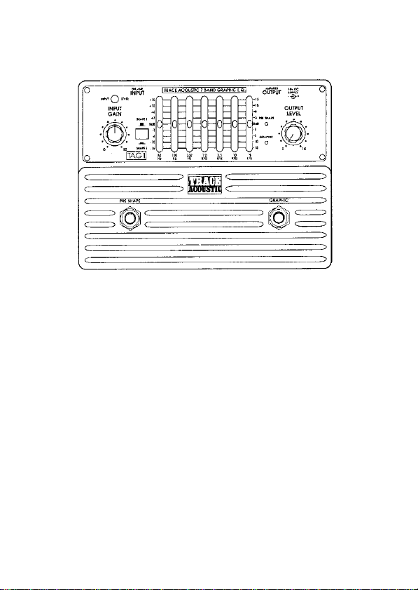
Connections and controls
Power to the unit is supplied from the two internal 9 volt batteries or from the D.C.
SUPPLY socket on the back of the unit (this requires a regulated 18 volts mains
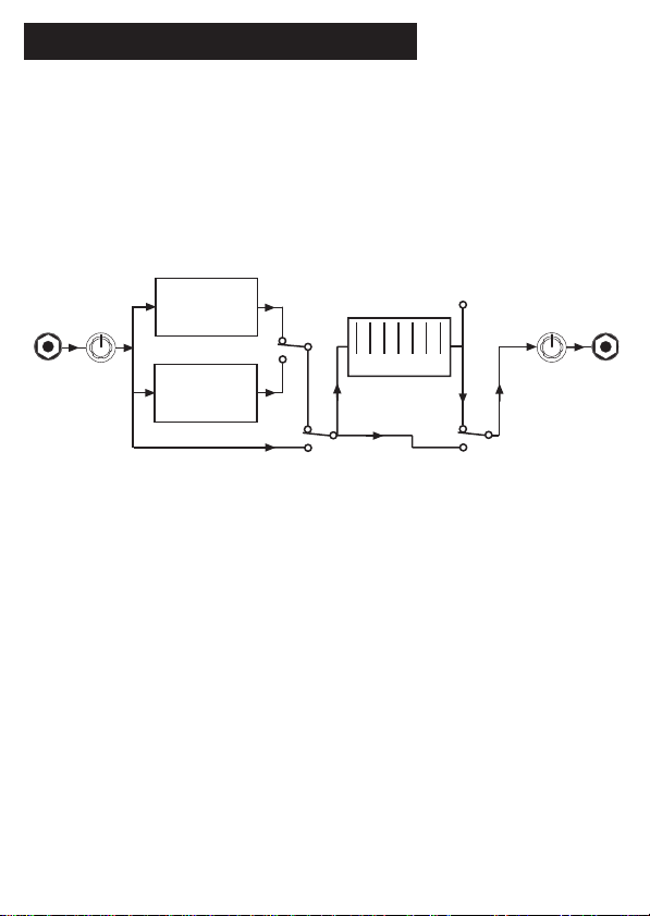
INPUT PRE SHAPE 1
PRE SHAPE 2
SHAPE IN/OUT GRAPHIC IN/OUT
7 BAND GRAPHIC
INPUT
LEVEL OUTPUT
LEVEL OUTPUT
LEVEL
LED
SHAPE
SELECT
TAG1 ACOUSTIC GRAPHIC EQUALISER PEDAL
General overview
The TAG1 pedal provides a range of equalisation facilities for acoustic instruments
in a convenient effects pedal format. It is more than just a graphic equaliser
designed specifically for acoustic instruments as it includes 2 PRE SHAPED
equalisations that are ideal for achieving instant and usable sounds. See BLOCK
DIAGRAM below:-
3
adaptor available from TRACE ELLIOT as an optional extra).
Power to the unit is turned on when a jack plug is inserted into the OUTPUT
socket.
Two LED’s indicate the ACTIVE status of the unit, these are PRE SHAPE and
GRAPHIC to indicate when those effects are switched into circuit.
If either of these LED’s should start to become dim then it is time to replace the
batteries.
Input control
The INPUT to the TAG1 is suitable for connection to the output of an acoustic
instrument that has its own inbuilt preamp. If however your signal is coming
directly from a PIEZO pickup with no preamplifier then you will need to correctly
match the impedance of this signal to the input of the TAG1, this can be done by
using a TAP1 acoustic preamp prior to the TAG1 input socket. Failure to correctly
match the impedances will result in a loss of instrument tone.
The INPUT control is to allow you to set the input sensitivity of the unit to your
instrument, if this is not set to the optimum level level then you will not have full
use of the equalisation range available.
With your instrument plugged into the TAG1 and its own level control turned up
4

full play a few loud notes. Gradually increase the setting of the INPUT control, the
INPUT LEVEL LED should start off showing GREEN as you play and eventually turn
to RED as the INPUT control is increased. The optimum setting for this control is
when the LED shows GREEN for every note played with an occasional flick into the
RED on loud peaks.
It will be necessary to readjust this INPUT GAIN control after adjustment of the
graphic equaliser to ensure that the signal is not clipping.
Pre shape
Next to the INPUT GAIN control is the switch for selecting PRE SHAPE 1 or 2. The
selected PRE SHAPE sound is switched in and out with the footswitch below this
marked PRE SHAPE.
The PRE SHAPE facility is like a preset graphic equaliser built into the TAG1 that
you can switch in or out to modify the sound of the instrument.
PRE SHAPE 1 is the classic TRACE ACOUSTIC shape as found on the TA35, TA50,
TA100 and TA200 amplifiers, it adds a boost at both the low end and the high end
of the frequency spectrum as well as a cut at mid frequencies.
PRE SHAPE 2 is a gentler equalisation providing a wider bandwidth boost at low
frequencies, less of a mid cut and a slight boost at higher frequencies. This is a
less extreme E.Q. than PRE SHAPE 1.
Both these pre shaped sounds may be used with or without the GRAPHIC
EQUALISATION section being switched in.
Graphic equaliser
A carefully designed GRAPHIC EQUALISER is a very flexible way of varying the
sound of an instrument and if properly used will provide an extremely powerful
method of tone shaping for your instrument.
The TAG1 has a 7 band GRAPHIC EQUALISER that can be switched IN or OUT of
the signal path from the right hand foot switch. Because of the flexibility and
massive BOOST and CUT potential of the GRAPHIC it is important to know how to
get the best from it.
5

It is equally important to know how to avoid the problems that can be associated
with its incorrect use, so firstly here is a list of things not to do, and why:-
1. Do not fully boost just one frequency band as this will tend to emphasise a
small range of notes producing a PEAKY and not very useful sound.
2. Do not boost or cut all frequencies as this will have the same effect as
increasing or decreasing the overall volume level without affecting the tonal
characteristics of the sound.
3. Do not use excessive bottom (50Hz) boost on the graphic as this will tend to
accentuate any acoustic feedback problems.
4. Do not use excessive top boost; this will tend to add a lot of HISS to the sound
(especially with active instruments).
The 7 sliders have been provided to give you full control at a number of
frequencies providing a flexible and comprehensive EQ system for the discerning
user.
Having got out of the way the things NO TO DO we move on to what can do with
the GRAPHIC EQUALISATION section. Basically you can do whatever you like as
long as you bear in mind the DON’TS and follow two simple rules, these are:-
1. Try to keep the slider settings balanced around the OdB line on the graphic.
2. Try to set the sliders in a smooth, gentle curve, as setting adjacent sliders at
opposite extremes will give sharp peaks and troughs in the sound, emphasising
some notes and killing others.
Switch the graphic IN and experiment with the available sounds.
N.B. Don’t forget to re-adjust the INPUT GAIN setting once you have altered the
graphic. This is necessary because altering the graphic will change the overall gain
and the level indicating circuit monitors the signal at a number of places to ensure
that clipping or distortion is not occurring at any stage. Consequently changing the
gain will change the reading on the LED and you will have to re-adjust the INPUT
GAIN control to compensate.
Output level control
The OUTPUT LEVEL control adjusts the level of signal from the TAG1 pedal, adjust
this to suit either the input or the effects return to your amplifier.
6

Connection within your system
The TAG1 pedal can be used IN LINE on the front end of your amplification system
with your instrument plugged directly into the INPUT and its OUTPUT taken to the
input of your amplifier, or if you have an effects loop it may be used connected
into this loop.
If you are already a TRACE ACOUSTIC user and you are adding the TAG1 pedal to
your system then you will find the results will be different between using it on the
front end and in the effects loop. The reason for this is that on the front end the
TAG1 is working prior to the amplifiers EQ whilst in the effects loop it is actually
placed after the amplifiers EQ, you may want to experiment with both methods to
discover which you prefer.
Replacing the batteries
When either the RED LED’s start to become dim or the INPUT LEVEL LED starts to
show an orangy red most of the time then it is time to replace the batteries.
The access to the batteries is through the bottom plate of the unit, by removing the
one small screw that secures the battery cover plate in position. Lift the battery
body from the outside edge of the unit to remove either battery. Always replace
both batteries at the same time.
For maximum life always use higher power type batteries, this should then give
you useful working life of approximately 100 hours. Remember to always unplug
the unit when not in use to conserve battery life.
An A.C. mains adaptor is available for the TAG1 pedal, this is a special 18v
regulated D.C. unit and is available from TRACE ELLIOT as an optional extra. Do
not use any other A.C. adaptor to power this pedal.
7

TAG1 pedal - Technical Specifications
INPUT
Impedance 250k Ohms
Signal level 600mV nominal, 6v max.
OUTPUT
Impedance 15k Ohms
Signal level nominal level 600mV.
SUPPLY
Internal - 18v from 2, 9v batteries (MN1604)
Average load - 6.5mA
Max. load - 10mA
Average life - 75 hours
External supply - 18v DC adaptor
Centre pin negative.
8

INPUT INPUT
LEVEL
OUTPUT
LEVEL OUTPUT
LEVEL
LED
NOTCH
FREQ
LO-TRIM HI-TRIM NOTCH IN/OUT SHAPE IN/OUT
HI/LO EQ
NOTCH FILTER
PRE SHAPE
CIRCUIT
BALANCED D.I.
VERY HIGH
INPUT IMPEDANCE
BUFFER
TAP1 ACOUSTIC PREAMP PEDAL
General overview
The TAP1 pedal is a complete acoustic guitar preamp and balanced D.I. box with
suitable equalisation and a notch filter (anti feedback) allowing the acoustic
guitarist to achieve a trouble free amplified sound that is perfectly matched to his
instrument whether it has just a PIEZO pickup or an inbuilt preamplifier. It provides
outputs suitable for connection to an on stage amplification system and for direct
connection to a balanced input on a mixing desk for the main front of house P.A.
All this is contained in a compact, easily portable, rugged effects pedal format.
See BLOCK DIAGRAM below:-
We at TRACE ELLIOT consider that one battery of 9 volts does not give sufficient
headroom in the circuitry for the dynamic peaks in the signal from your
instrument, so as not to compromise the signal integrity the TAP1 pedal uses two
9 volt batteries to give an internal power supply of 18 volts.
9
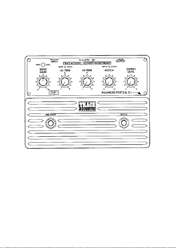
Connections and controls
Power to the unit is supplied from the two internal 9 volt batteries or from the
D.C. SUPPLY socket on the back of the unit (this requires a regulated 18 volts
mains adaptor available from TRACE ELLIOT as an optional extra).
Power to the unit is turned on when a jack plug is inserted into the INPUT socket.
Two LED’s indicate the ACTIVE status of the unit, these are SHAPE ACTIVE and
NOTCH ACTIVE to indicate when those effects are switched into circuit.
If either of these LED’s should start to become dim then it is time to replace the
batteries.
Input socket
The INPUT to the TAP1 is suitable for connection to the output of any acoustic
instrument whether it has its own inbuilt preamp or not. If your signal is coming
directly from a PIEZO pickup with no preamplifier then it is extremely important to
correctly match the impedance of the PIEZO pickup to the input of the
10

amplification system that you are using, the TAP1 is designed to do this.
An amplification system such as the TRACE ACOUSTIC RANGE that is specifically
designed for acoustic instruments is the only type of amplification that will
correctly match the acoustic instruments. Any other amplifier whether a guitar
amplifier, keyboard amplifier or a full P.A. system will not have high enough
impedance inputs to correctly match to a PIEZO pickup. Failure to correctly match
the impedance will result in a serious loss of instrument tone.
Input gain control
The INPUT GAIN control is to allow you to set the input sensitivity of the unit to
your instrument, if this is not set to the optimum level then you will not have full
use of the equalisation range or the benefit of the excellent signal to noise ratio
available.
With your instrument plugged into the TAP1 and the instrument level control
turned up full, play a few loud notes. Gradually increase the setting of the INPUT
GAIN control, the INPUT LEVEL LED should start off showing GREEN as you play
and eventually turn to RED as the INPUT GAIN control is advanced. The optimum
setting for this control is when the LED shows GREEN for every note played with
an occasional flick into the RED on loud peaks.
It may be necessary to readjust this INPUT GAIN control after adjustment of the
equalisation (HI-TRIM 7 LO-TRIM controls) to ensure that the signal is not
clipping.
Lo-trim control
The LO-TRIM control is for adjusting the bass end of the instruments sound. This
is a BOOST and CUT type of control i.e. its FLAT (no EQ) position is in its central
position with BOOST when the control is turned to the right and CUT when turned
to the left.
The range and effect of this control has been tailored to best suit the requirements
of an acoustic instrument. In use try not to add too much BOOST as this increases
the possibility of feedback from the body of the instrument.
Always start with this control set to its ‘O’ or FLAT position and get to know the
amplified flat sound of your instrument well before starting to add any
equalisation.
11

Hi-trim control
The HI-TRIM control is for adjusting the treble end of the instruments sound. This
is a BOOST and CUT type of control i.e. its FLAT (no EQ) position is in its central
position with BOOST when the control is turned to the right and CUT when turned
to the left.
The range and effect of this control has been tailored to best suit the requirements
of an acoustic instrument.
Always start with this control set to its ‘O’ or FLAT position and get to know the
amplified flat sound of your instrument well before starting to add any
equalisation.
Preshape
In addition to the HI and LO TRIM equalisation controls there is a PRESHAPE
facility built into the TAP1. This may be switched in and out with the left hand foot
switch and is in circuit when the SHAPE ACTIVE LED above the LO-TRIM control is
lit.
The PRESHAPE facility is like a preset graphic equaliser built into the TAP1 that
you can switch in and out to modify the sound of the instrument.
The PRESHAPE is the classic TRACE ACOUSTIC shape as found on the TA35,
TA50, TA100 and TA200 amplifiers, it adds a boost at both the low end and the
high end of the frequency spectrum as well as a cut at mid frequencies. Its sound
is ideal for both finger picking and strumming styles of playing and adds a
‘Sparkle’ to the amplified sound.
Notch control
The NOTCH is a special type of control that removes a narrow band of frequencies
from the audio spectrum. The band of frequencies removed is kept very narrow so
as not to unduly effect the sound of the instrument. The NOTCH control adjusts
where in the audio range this band of frequencies is placed and within the TAP1
the adjustable range has been optimised for acoustic guitar.
12

This is an extremely useful device for an acoustic guitar as it allows the natural
body resonance of the instrument to be ‘Tuned Out’ which in turn enables a far
higher level of amplification to be achieved before feedback.
The NOTCH may be switched in and out with the right hand foot switch marked
NOTCH and is active when the LED above the NOTCH control is lit.
To use the NOTCH facility to its best advantage first of all switch it out of circuit i.e.
NOTCH ACTIVE LED is off, turn up the OUTPUT LEVEL control until the
instrument starts to feedback (it is very often the ‘A’ string that goes first), switch
the NOTCH in and adjust the NOTCH control until the feedback either goes away or
is reduced. This is the optimum position for tour instrument.
Feedback is the amplified sound of the guitar getting back to the instrument from
the loud speakers and exciting it into resonance. Your position relative to the
amplification system will affect the sensitivity of your instrument to feedback. If
you have adjusted the NOTCH control to its optimum position to reduce any initial
feedback and you are still having trouble then you will either have to change your
position relative to the speakers or turn the system down a bit.
Output level control
The OUTPUT LEVEL control adjusts the level of signal from the TAP1 pedal to the
output jack on the back of the unit, adjust this to suit the input of your amplifier.
This control has no effect on the level from the D.I. output on the side of the unit.
D.I. balanced output
The BALANCED D.I. output is an XLR output intended for direct connection to the
low impedance balanced microphone input on a mixing console. The level of
output from this is fixed and will be correct if the units INPUT GAIN control has
been correctly set as instructed.
This allows for a direct, noise free, matched connection to any mixing console for
direct injection into the P.A. or for recording, leaving the jack output with its own
OUTPUT LEVEL control for adjusting your on stage monitor volume through a
suitable amplifier, a TRACE ACOUSTIC amplifier is obviously best for this
application.
13

The signal from the BALANCED D.I. is post EQ but prior to the TAP1 OUTPUT
LEVEL control. In a live situation the TAP1 is possibly all you need with your
instrument plugged into its input and the D.I. output plugged into the P.A.
Connection within your system
The TAP1 pedal can be used IN LINE on the front end of your amplification system
with your instrument plugged directly into the INPUT and its OUTPUT taken to the
input of your amplifier, or if you have other effects units such as the TAC1 or the
TAG1 it may be used as a front end preamplifier to perfectly match your
instrument to the input of either of these effects units or indeed any other effects
unit you may wish to use.
Replacing the batteries
When either the RED LED’s start to become dim or the INPUT LEVEL LED starts to
show an orangy red most of the time then it is time to replace the batteries.
The access to the batteries is through the bottom plate of the unit, by removing the
one small screw that secures the battery cover plate in position. Lift the battery
body from the outside edge of the unit to remove either battery. Always replace
both batteries at the same time.
For maximum life always use higher power type batteries, this should then give
you useful working life of approximately 100 hours. Remember to always unplug
the unit when not in use to conserve battery life.
An A.C. mains adaptor is available for the TAP1 pedal, this is a special 18v
regulated D.C. unit and is available from TRACE ELLIOT as an optional extra. Do
not use any other A.C. adaptor to power this pedal.
14

TAP1 pedal - technical specifications
INPUT
Impedance 4 meg Ohms
Signal level 150mV to 6v max.
JACK OUTPUT
Impedance 15k Ohms.
Signal level Nominal level 600mV.
D.I. BALANCED XLR OUTPUT
Impedance 600 Ohms balanced.
Signal level 300mV nominal.
EQUALISATION
LO-TRIM + & - 15dB @ 150Hz
acoustically tailored.
HI-TRIM + & - 15dB @ 5kHz
acoustically tailored.
NOTCH
Range - 60 to 300Hz.
Attenuation - 18dB.
SUPPLY
Internal - 18v from 2, 9v batteries (MN1604).
Average load - 6.5mA.
Max Load - 8mA.
Average life - 75 hours.
External supply - 18v DC adaptor
Centre pin negative.
15
The TAC1 pedal can increase sustain on any note or harmonic, smooth out playing
dynamics, add definition to fast runs, provide a switchable volume boost, provide a
wide range of EQ’s that are easily and instantly adjustable, provide HIGH or LOW
compression or any combination of the two and can function in the effects loop or
on the front end of any amplification system.
We at TRACE ELLIOT consider that one battery of 9 volts does not give sufficient
headroom in the circuitry for the peaks in the signal from your instrument, so as
not to compromise the signal integrity the TAC1 pedal uses two 9 volt batteries to
give an internal power supply of 18 volts.
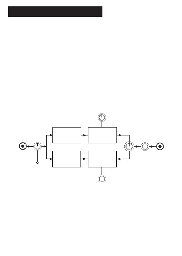
INPUT INPUT
INPUT
LEVEL
LEVEL
LED
OUTPUT
LEVEL
EQ BALANCE
HIGH PASS FILTER
HIGH COMPRESSION
LOW COMPRESSION
LOW PASS FILTER
FAST ATTACK
COMPRESSION
SLOW ATTACK
COMPRESSION
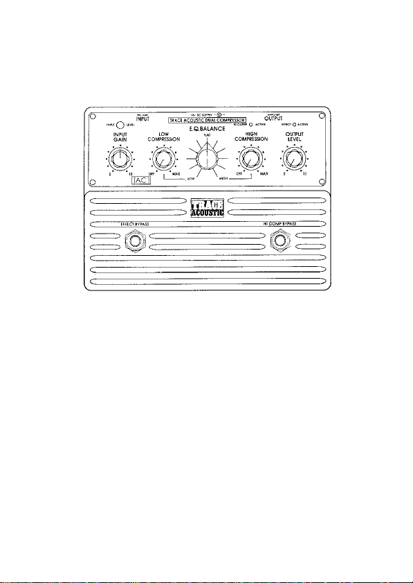
TAC1 - ACOUSTIC COMPRESSOR PEDAL
General overview
It is important to understand a little of what goes on inside the TAC1 pedal to give
you an idea of what is happening to your sound as you adjust the units controls.
To help with this a short description follows prior to the actual operating
instructions.
The TAC1 DUAL COMPRESSOR is two separate compressors in one unit, each
compressor has its parameters set to suit the frequency band that it is dealing with
i.e. Fast attack for the High frequencies and Slow attack for the Low frequencies.
Two input filters are used to split the signal into its High and Low frequency
components, the output from these feed the High and Low compressors.
The EQ BALANCE control sets a crossfade between the output of the two
compressors and provides an extremely versatile and entirely new form of
powerful tone control. See BLOCK DIAGRAM below:-
16
Connections and controls
Power to the unit is supplied from the two internal 9 volt batteries or from the DC
SUPPLY socket on the back of the unit (this requires a regulated 18 volts mains
adaptor available from TRACE ELLIOT as an optional extra).
Power to the unit is turned on when a jack plug is inserted into the INPUT socket.
Two LED’s indicate the ACTIVE status of the unit, these are EFFECT ACTIVE above
the OUTPUT control to indicate when the effect is switched into circuit, and HI
COMP ACTIVE to indicate when the HIGH COMPRESSION is switched into circuit.
This second LED will indicate the status of the HIGH COMPRESSION even when
the unit is in bypass mode i.e. EFFECT ACTIVE off, to let you know the current
condition of the HIGH COMPRESSION prior to switching the overall effect into
circuit i.e. EFFECT ACTIVE on.
If either of these LED’s should start to become dim then it is time to replace the
batteries.
Input & input gain control
The INPUT to the TAC1 is suitable for connection to the output of an acoustic
instrument that has its own inbuilt preamp. If however your signal is coming
directly from a PIEZO pickup with no preamplifier then you will need to correctly
match the impedance of this signal to the input of the TAC1, this can be done by
using a TAP1 acoustic preamp prior to the TAC1 input socket. Failure to correctly
match the impedances will result in a loss of instrument tone.
17

18
The INPUT GAIN control is to allow you to set the input sensitivity of the unit to
your instrument, if this is not set to the optimum level then you will not have full
use of the compression range available.
With your instrument plugged into the TAC1 and its own level control turned up
full play a few loud notes. Gradually increase the setting of the INPUT control, the
INPUT LEVEL LED should start off showing GREEN as you play and eventually turn
to RED as the INPUT control is increased. The optimum setting for this control is
when the LED shows GREEN for every note played with an occasional flick into
into the RED on loud peaks.
Compression
The compression within the TAC1 pedal has been split into two entirely separate
compressors, one optimised for LOW frequencies and one optimised for HIGH
frequencies, but both individually adjustable by the user.
Separate attack and release characteristics are used for the HIGH and LOW
compression, fast for the HIGH and medium to slow for the LOW. Fast is needed
on the HIGH compression in order to catch initial high frequency transients on
striking the string. A slower attack is used on the lower frequencies so as not to
distort the shape of bass note.
If the slower attack were to be used on the high frequencies any initial transient
would get through unchecked and subsequent transients would disappear as the
low bass compression would not have time to recover, i.e. the release is too slow
for the high frequencies.
Low compression
The LOW frequency compressor acts upon the low pass signal only.
Applying the compression to the LOW PASS gives a fat bottom end to the sound
without losing the upper frequency attack characteristics of the note. It is
somewhat of a less processed sounding effect than full range compression but
works extremely well in smoothing out bass signal peaks.
You will also find that a degree of LOW compression will add definition to your
playing, bringing out the notes within a run without loss of the upper dynamics.
As the compression control is advanced and compression is applied to the signal
the overall level of volume is compensated for, if this were not done then adding
compression would have the effect of reducing the volume of the sound as the
available dynamics are reduced.

The compression within the TAC1 pedal has been added as a means of creatively
modifying your sound and as such becomes part and parcel of the overall sound
character that you create, and not merely as an effect.
By turning either compression control to its fully anticlockwise position removes
all compression from the sound without significantly altering the overall volume.
High compression
The HIGH frequency compressor acts upon the high pass signal only.
The HIGH COMPRESSION should be used with care as it is directly affecting the
attack portion of the sound, this can be used to good effect but moderation should
always be exercised when applying the high compression.
As the compression control is advanced and compression is applied to the signal
the overall level of volume is compensated for, if this were not done then adding
compression would have the effect of reducing the volume of the sound as the
available dynamics are reduced.
However in the case of the HIGH compression circuit this means that when no
signal is present then additional gain is added at high frequencies. The more the
compression control is advanced the more additional gain. This in itself presents
no problem as the electronics within the TAC1 produce very little noise. However if
you are using an active instrument you may well find that adding high
compression adds HISS to the sound, this HISS is coming from the active
electronics within your instrument, this can be proved by unplugging the
instrument from the TAC1 input socket, and the HISS goes away.
The two compression circuits can be set individually to produce some useful
sounds, i.e. with LOW set to about half to tighten up the bottom end of the sound,
the HIGH can be varied in conjunction with the EQ BALANCE control to produce a
variety of different attacks to the note to suit many different styles of playing.
EQ balance
This is an entirely new concept in terms of a means of EQ adjustment. The signal
entering the TAC1 pedal is a full range mono signal, this is then split into two, with
one part containing the HIGH PASS (upper frequency) content of the signal and the
other part containing the LOW PASS (lower frequency) content of the signal.
Both parts pass through their own separate compression circuitry and then on to
the EQ BALANCE control. Here they are re-combined into a single full range signal
19

once again that contains a mix of the HIGH and LOW frequencies in proportion to
the setting of the EQ BALANCE control.
As can be seen from the block diagram, the EQ BALANCE control varies between
HIGH and LOW and is FLAT in its centre position.
The action of this control can be envisaged by imagining a pivot point at the centre
of the frequency spectrum of your instrument about which the EQ of the
instrument can be swung.
Turning the EQ BALANCE control to the right increases the top end and decreases
the bottom end, while turning it to the left decreases the top end and increases the
bottom end.
The internal filter circuits that feed this control have been designed to allow the
HIGH PASS and LOW PASS signals to overlap in frequency so that fully LOW or
fully HIGH may be used as individually useful sounds in their own right.
Whether or not you understand its action, you will find the EQ BALANCE control a
very easy and flexible way to instantly modify your sound over a wide range.
Output control
The OUTPUT control is to set a balance between the levels when the effect is
switched in or out, this can be used in two ways by either adjusting it to give the
same overall level but just the addition of compression or EQ when switched in, or
to give a level boost when the effect is switched on.
Connection within your system
The TAC1 pedal can be used IN LINE on the front end of your amplification system
with your instrument plugged directly into the INPUT and its OUTPUT taken to the
input of your amplifier, or if you have an effects loop it may be used connected
into this loop.
If you are already a TRACE ACOUSTIC user and you are adding the TAC1 pedal to
your system then you will find the results will be different between using the TAC1
pedal on the front end and in the effects loop. The reason for this is that on the
front end the TAC1 is working prior to the EQ (Hi and Lo Trim and the graphic )
whilst in the effects loop it is actually placed after the EQ, you may want to
experiment with both methods to discover which you prefer.
20
This manual suits for next models
2


