Track It TV Satellite TV Dish & Receiver Instruction Manual

Track It TV™ - OPERATION &MOUNTING
Overview
Satellite
TV Dish
TITV
Unit
Use Any Satellite TV Dish & Receiver
The TITV (Track It TV™) Unit works with any DSS
(Digital Satellite System) dish and receiver, domestic or
international, that the user provides. Take advantage of the latest
multi-satellite dishes, HDTV dishes, or larger 24” (or even some
lightweight 32” dishes) for reception in “fringe” areas of the world.
The robust motor and construction of the Track It TV™ Unit lets you
mount any of these dishes onto the TITV rotating shaft, so that you can enjoy high
quality digital satellite TV programming while swinging at anchor on your vessel.
Accurate Tracking
The Track It TV™ Unit uses an extremely accurate digital compass
with no moving parts for tracking. A rapid compass sampling rate –
over 30 times per second – and magnetic direction resolution of 1/10º,
mean that the unit reacts very quickly to any movement of your vessel.
This translates into very accurate tracking of the satellite TV signal,
usually within 1/4º to 1/2º. This is well within the maximum horizontal
tracking “window” of 6º for a typical 18” dish (4.5º for a 24” dish or 3.8º for
a 32” dish). The width of this “window” depends on how accurately the dish
elevation is set manually on the dish, since the vertical “window” of reception
is also 6º for a typical 18” dish. We show you easy techniques for setting
elevation to the center of this vertical “window” of reception, so even in less
than smooth anchorages you will continue to receive satellite TV programming.
Quick Signal Recovery
An advantage the compass driven Track It TV™ Unit has over the signal driven tracking
of higher priced units, is that if the TV signal is lost due to passing an obstruction while
motoring, or due to a large wake that causes your boat to roll heavily, as soon as the
obstruction or water disturbance has passed, the TV signal immediately reappears, since
our compass continues to track accurately without the signal. The same events also cause
the loss of TV signal by the typical signal driven tracking unit. But it often takes an
annoying amount of time for such units to search and locate the signal again before
tracking resumes.
Mounting Flexibility And Light Weight
The slim, light-weight TITV Unit can often be tucked into locations where larger and
heavier dome style dishes cannot. The unit is very easy to mount on 1 or 2 railings, on an
aluminum pole that can be put almost anywhere to give required height to clear
obstructions, as well as on decks or on the sides or tops of arches or cabins. Over many
years working with customers, we have learned the best way to take advantage of the
great mounting flexibilities provided by the TITV design, and it is all documented here.
Revised 3/15/2007 Page 1
Track It TV™ - OPERATION &MOUNTING
Overview
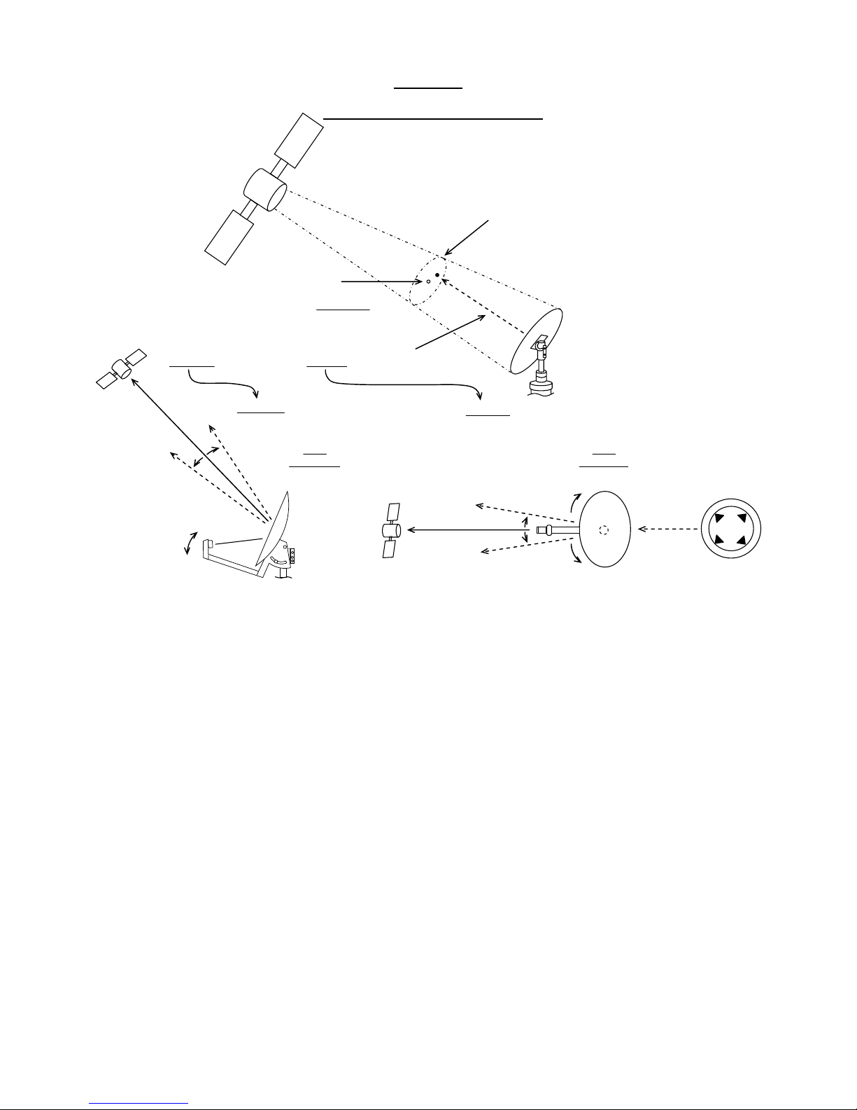
(1) Satellite
Beaming
TV Signal
To Earth
(
3) 6° “Circle of Reception” (radius of 3°)
within which dish must remain pointed
to receive the TV signal from the satellite.
Outside this circle the signal will be lost.
(2) 18” Satellite TV
Dish mounted on
Track It TV™
on boat that swings,
rolls and pitches
(4) Best signal is at
Satellite TV Tracking Concepts
th
“ -
e center of 6°
Circle of Reception”
called the “sweetspot
”
(5) This Satellite TV Dish is pointing within the
“Circle of Reception”, even though pointed up in
elevation
and to the right in azimuth about 1-1/2°
(6) Elevation is set manually by the user
as close as possible to the sweetspot.(7) Azimuth is set as close as possible to the sweetspot
by pressing Right and Left buttons on the Button Box.
Dish
Top View
compass
azimuth
Compass
center of circle
in azimuth
S
w
E
N
edgeofcircle
+3°
-3°
edgeofcircle
Left
Right
Dish
Side View
edgeofcircle
edgeofcircle
+3°
-3°
centerof circle
in elevation
up / down
(1) The TV satellite beams its signal to earth.
(2) The satellite TV dish that must receive this signal is mounted on the TITV unit on
your boat.
(3) The “target” that the dish must remain pointed at is the center of a 6º “circle of
reception” - outside this circle the dish will not “see” the satellite TV signal.
(4) The user should strive to aim the dish at the sweet spot (the center of the 6º “circle of
reception” shown with small circle) for the best signal.
(5) This shows that the dish is pointed up in elevation from (4) about 1-1/2º, and to the
right in azimuth from (4) about 1-1/2º, but will still receive the TV signal because it is
within the 6º “circle of reception”, but it is better to move the dish toward the sweet spot.
(6) Elevation must be set manually by the user moving the dish, up or down, to point the
dish as close as possible to the sweet spot.
(7) Azimuth is set pressing the Right and Left buttons on the button box to point the dish
as close as possible to the sweet spot. Memorize this best setting for future tracking by
pressing (2nd Func) and (Reset) Find buttons simultaneously.
Revised 3/15/2007 Page 2
Track It TV™ - OPERATION &MOUNTING
Overview
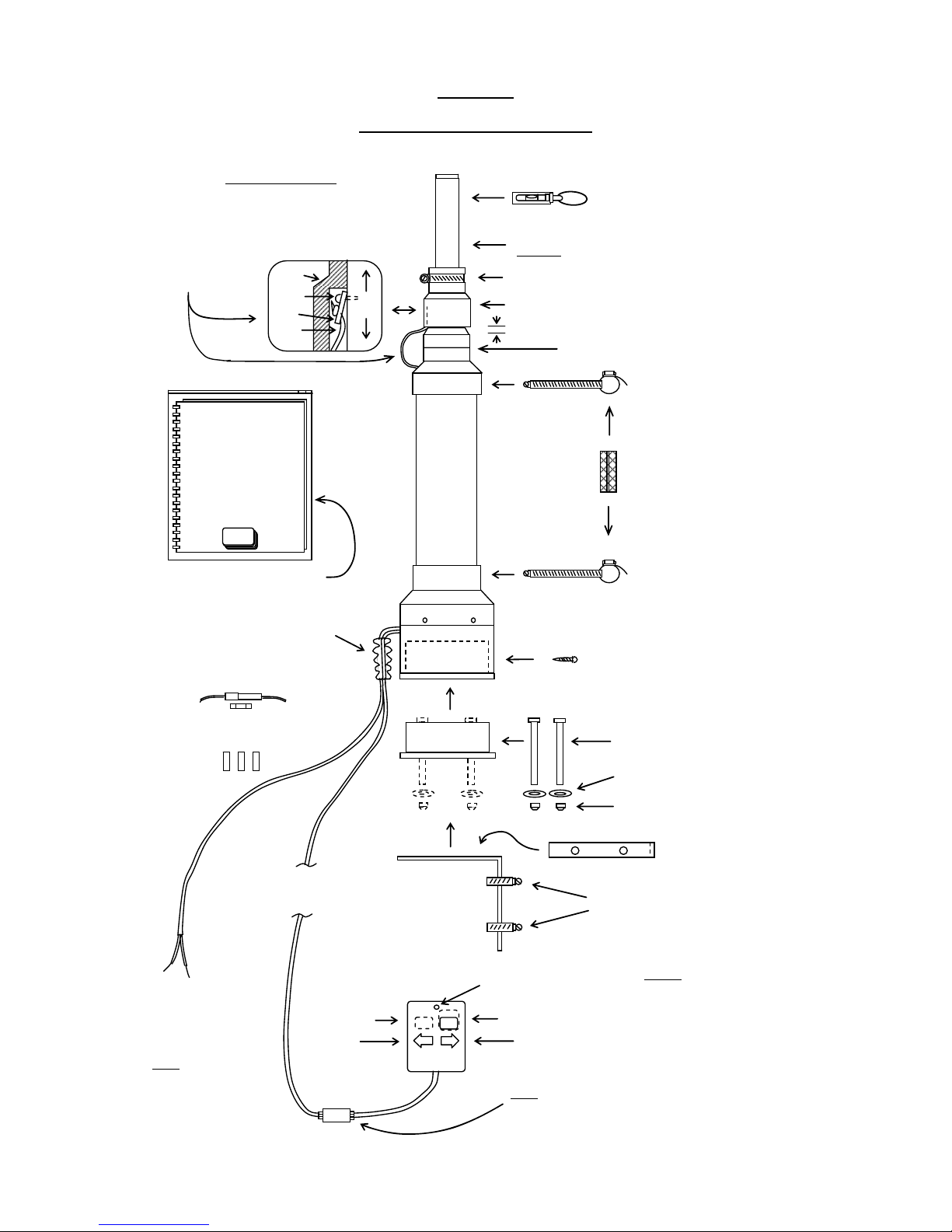
Track It TV™ Shipped Parts
Shaft turns: rotated by motor
(Caution: do not twist by hand)
Large & small hose clamps*
can attach unit to railing
Warranty voided if:
1. Rubber shaft seal removed
2. Screw, clip or 720º limit cord removed
Split vinyl hose under small
hose clamps can protect
SS rails & prevent slippage
#8 x 3/4” Screw can secure Base Adapter
to Tracking Unit – DO NOT GLUE BASE
ADAPTER INTO BASE OF UNIT
TITV
Unit
Base
Adapter
Rubber shaft seal – prevents water entry
Large & small hose clamps*
can attach unit to railing
1/4” x 3” Bolts (2) can attach Base
Adapter to L-Bracket
Large fender washers (2)
Lock nuts (2)
Small hose clamps* (2) can attach
L-Bracket to vertical stanchions
or mounting poles
Aluminum
L-Bracket
(3/16” x 1”)
Track It TV
™
Operation Manual
TITV
cards
Plus additional instructions
in zip lock bag
(Reset) Find
Right
(2
nd
Func)
Left
LED light
2nd
Func
Reset
Find
Right
Left
Track It TV™
Button
Box
Coupler
40’ Control Cable
(6-wire phone cable)
12V to 24V
DC Power
Cable
(+ = red)**
Level to make FMTV
tracking unit vertical
Note: RJ11 plugs allow removal of Button Box
to facilitate concealed control cable installation
Base
Adapter
“Split Loom” corrugated cable
protects wire from UV damage
(only sample length supplied)
Hose clamp secures seal to rotating shaft
1/4” – prevents binding and chafe of limit cord
720º limit cord –
prevents damage to
Internal wires
SHAFT
SHAFT
SEAL
CLIP
CORD
SCREW
Detail
3 amp fuse and holder
for permanent 12V power
3 Ancor connectors for
permanent 12V power
Top view – 3/8” holes
allow some bolt movement
to help make unit vertical
* NOTE: The 6 SS hose clamps
supplied with the unit are non-
magnetic – ONLY USE NON-
MAGNETIC CLAMPS NEAR
COMPASS!
** Note: TITV
Tracking Unit is
polarity protected
Compass located inside case in this area*
Revised 3/15/2007 Page 3

Track It TV™ - OPERATION &MOUNTING
Overview
Extending or Shortening Button Box Control Cable
RJ11
Coupler*
(“reversing”)
6-wire
RJ11
plug*
Tab up
6-wire flat phone
cable extension
blue wire 6-wire
RJ11
plug*
Tab up
6-wire
RJ11
plug*
Tab up
6-wire
RJ11
plug*
Tab up
RJ11
Coupler*
(“reversing”) Button
Box
blue wire
6-wire flat phone
cable to TITV unit
blue wire
The drawing below shows how the button box control cable can be extended if needed,
using another length of 6-wire modular flat telephone cable:
Also, the control cable from the unit can be made shorter, by cutting and crimping on a
new 6-wire RJ11 plug.
Major Components for mounting
32”
5”
Dish On
Shaft
Rotates
Compass
Inside Here
Bottom
Support
Here
(1)
TITV
Unit
(10 lbs.)
(3)
Base
Adapter
(4)
L-Bracket
Top
Support
Here
14” (2)
Dish
(5 lbs.)
18”
8”
The four major components for mounting are shown in the drawing below:
(1) Track It TV™ Unit; (2) Satellite TV Dish; (3) Base Adapter; and (4) L-Bracket.
Important dimensions and weights
are shown in the drawing. Dish
dimensions are typical, but can vary
several inches from those listed. The
base adapter, if used, fits inside the
bottom of the unit as illustrated. The
L-bracket, if used, is bolted to the
base adapter. The dish is mounted on
the rotating shaft that rotates to track
the satellite as the boat turns, guided
by the compass inside the shaft. The
unit must have both top and bottom
supports when mounted as shown.
Revised 3/15/2007 Page 4
Track It TV™ - OPERATION &MOUNTING
Overview
Mounting Methods Categorized
The following categorizes the mounting methods we have found from experience to work
well for Track It TV™. We recommend trying the easiest one first. They are divided and
ranked in order of difficulty as follows:
(1) Easy 1-rail/stanchion or 2-rail mountings.
(2) Versatile pole mountings.
(3) Arch or cabin side mountings.
(4) Standalone deck or limited area surface mountings.
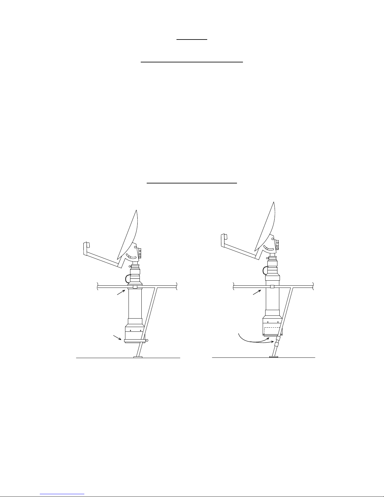
Deck
Railing
large + small
hose clamp *
large
hose clamp *
(1)
Quick
1-Rail
* No shims required Deck
Railing
large + small
hose clamp *
Base Adapter,
L-Bracket,
2 hose clamps *
(2)
L-Bracket
1-Rail
* No shims required
Each mounting method covered briefly below has a much more detailed explanation in
the MOUNTING APPENDIX of the full Track It TV™ Operation Manual.
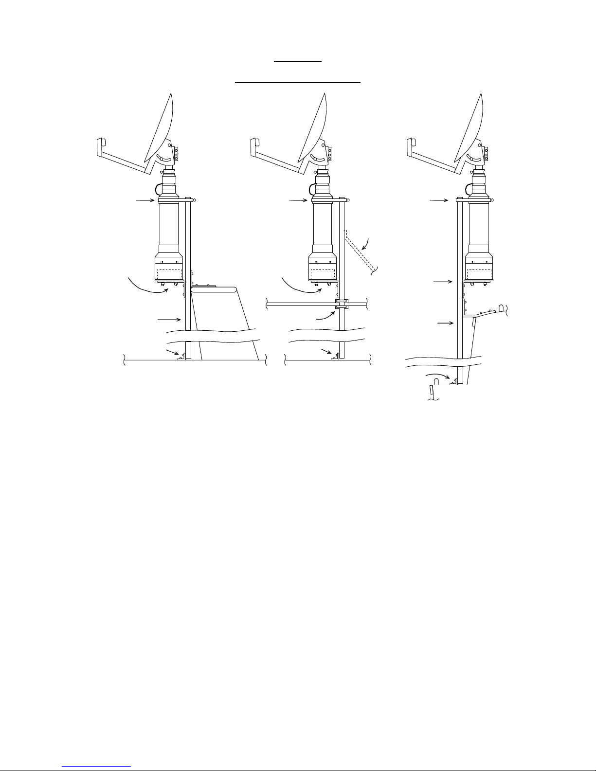
1-Rail/Stanchion Mountings
(1) With just a few hose clamps near a stanchion, the unit can be quickly mounted and
made vertical with absolutely no shims.
(2) Similar to (1), but results in an even more rigid installation using the Base Adapter
and L-Bracket. It is also easier to mount and dismount the unit for off-season or
hurricane storage.
Revised 3/15/2007 Page 5
Track It TV™ - OPERATION &MOUNTING
Overview
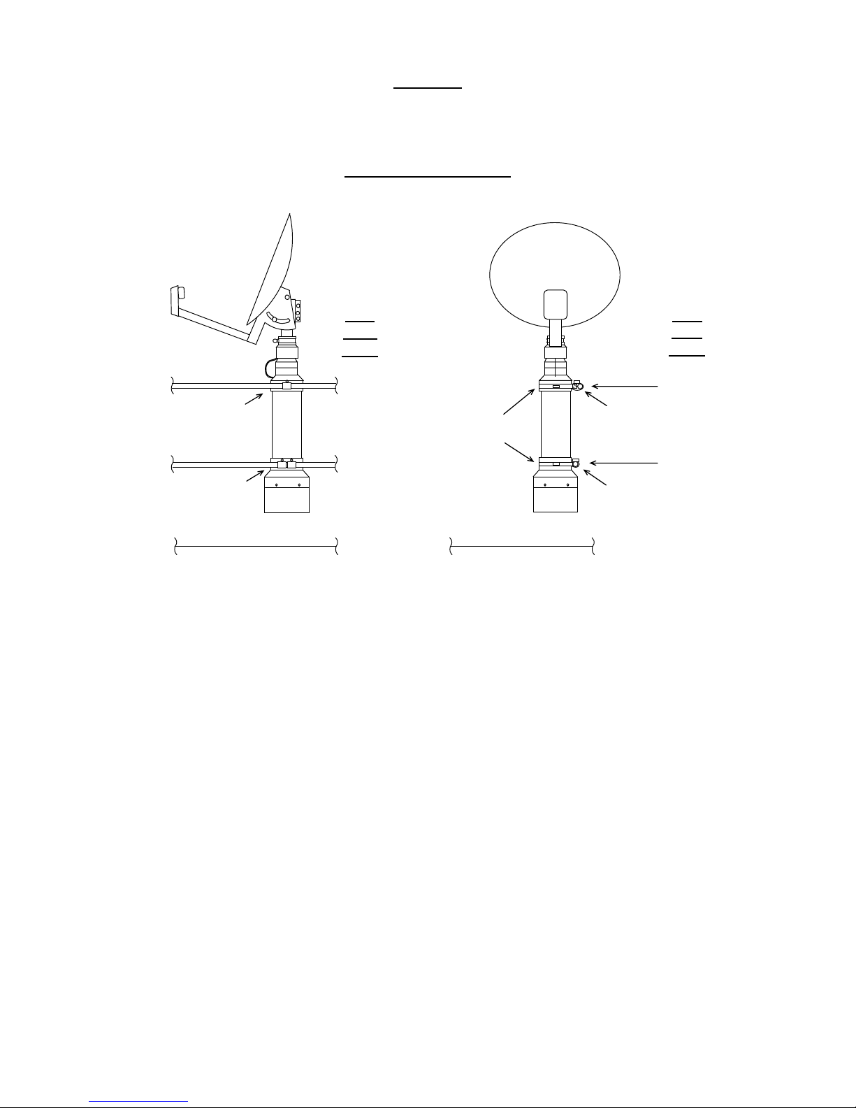
Quick 2-Rail Mounting
Railing
Rail
Side
View
Railing
large + 1 small
hose clamp
with shim *
large + 2 small
hose clamps
to prevent
twisting Deck
* shim sized
to make
unit vertical
Railing
large
hose clamps
2 small
hose clamps
to prevent
twisting
Deck
Railing
1 small
hose clamp
with shim *
Rail
End
View
With just a few hose clamps more rail area is opened up with this 2-rail mounting, but a
shim is usually needed to make unit vertical.
The 1-rail and 2-rail mountings are the easiest and quickest to use, but may not satisfy
your need for a higher mounting location to clear an obstruction, or to give working
room, or to allow a position that is far enough from some magnetic source that affects the
Track It TV™ compass.
Mounting inside the rail may be better than outside because pilings and docks may hit the
unit.
The next pages show more complex mountings that may be required to solve such
problems.
Revised 3/15/2007 Page 6
Track It TV™ - OPERATION &MOUNTING
Overview
Versatile Pole Mountings
arch
pole secured
to arch
large hose
clamp and
shim
(1)
Pole
Mount
Base
Adapter
&
L-Bracket
and deck
pole secured
to railing
railing
and deck
large hose
clamp and
shim
Base
Adapter
&
L-Bracket
(2)
Pole
Mount
other
options
for pole
support
and deck
pole secured
to cabin top
large hose
clamp and
shim
Base
Adapter
&
L-Bracket
(3)
Pole
Mount
The pole mount allows the TITV unit to be higher than
would normally be possible - above arches, railings or cabin tops,
without interfering with deck space. But if adjusting of dish elevation is required, don’t
make the unit too high. There is great flexibility in how high you can elevate the unit – or
it can even hang below an arch, railing or cabin side to achieve the precise dish height
desired. Attaching the TITV unit directly to an arch, railing or cabin side or top generally
limits such flexibility, and is often harder than the simple pole installation. The pole
material we like is readily available from metal warehouses, metal fabricators or welding
shops: 2” aluminum schedule 40 pipe (not electrical conduit) up to 8’ high. Pole
mounting is one of our favorite mountings, and second only to the rail mountings for
convenience, ease and flexibility of mounting.
(1) This option shows the pole attached to the deck and top of a radar arch – may be
preferable to direct attachment to the arch.
(2) This option shows the pole attached to the deck and a railing – useful for some extra
height above the railing.
(3) This option shows the pole attached to the deck and a cabin top – useful when the
side of the cabin is a preferred location
There are additional details of TITV Unit attachment to the pole, including information
on the shim that is needed, as well as various pole support alternatives.
Revised 3/15/2007 Page 7
Track It TV™ - OPERATION &MOUNTING
Overview
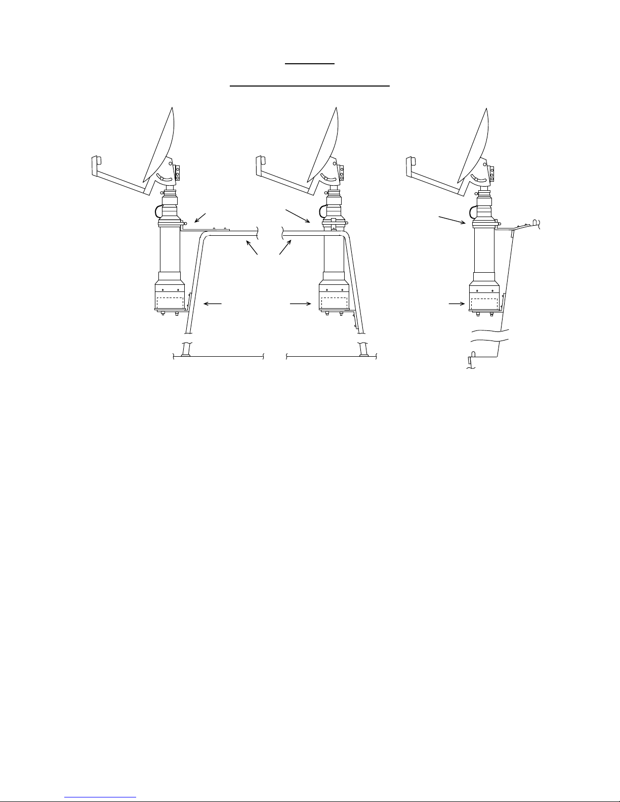
Arch or Cabin Side Mountings
(1)
Outside
Arch
(2)
Inside
Arch
Base Adapter
& aluminum
strap
aluminum strap
& large hose clamp
deck deck
arch
(3)
Cabin
Side
Base Adapter
& aluminum
strap
aluminum strap
& large hose
clamp
deck
The arch and cabin side mountings are also relatively easy to accomplish.
There is not as much height variation possible as with the pole mounting, but if these
height constraints are acceptable, you do avoid having to get an aluminum pole. The
aluminum strap we find most suitable for these mountings is 3/16” x 1”, thick enough for
strength, yet thin enough to bend.
(1) This shows what we call the “fire extinguisher” mounting, on the outside of an arch.
(2) This shows an inside the arch “hanging” mount. Detailed drawings show (with
another view) how the backward rake of most arches makes this possible.
(3) This again is the “fire extinguisher” mount, but this time on the side of a cabin.
Revised 3/15/2007 Page 8
Track It TV™ - OPERATION &MOUNTING
Overview
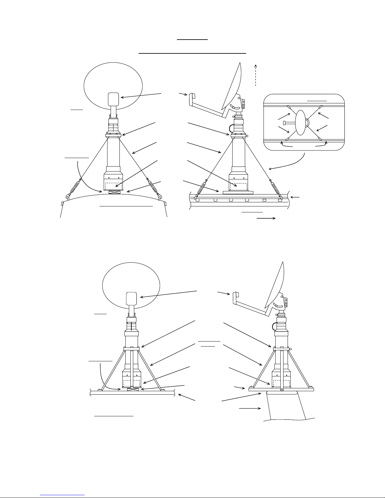
Deck or Limited Area Mountings
Base Adapter
screwed to
8” wood 2x4
8” 2x4
secured
to deck
dish
LNB
(1)
Deck Mount
large hose
clamp secures
4 wire stays
with swages
on ends
4 wires with
turnbuckles
Note:
slightly offset
2x4 allows
required air
circulation &
moisture to
escape from
bottom of
Base Adapter:
do not seal
cabin house looking forward to bow
options to move dish higher -
(extend PVC case and upper
support alternatives)
forward to bow
cabin house side view
grab rail
cabin house top view
dish unit
stays stays
grab rail
Arch
Side
View
Arch View Looking Forward
Note:
slightly offset
2x4 allows
required air
circulation &
moisture to
escape from
bottom of
Base Adapter:
do not seal
Forward
To Bow
arch top
18” wood 2x4
secured to arch
Base Adapter
screwed to 2x4
aluminum
braces*
large hose
clamp
dish
LNB
(2) Limited Area
Mount
* Aluminum braces may be either 3/8” x 1” aluminum strap,
or 3/4” aluminum electrical conduit with ends flattened
(1) This shows a typical mounting on a cabin house deck top, utilizing wire stays and
turnbuckles to support the top of the unit. Four wire stays must be used. There are
options to move dish higher off deck.
(2) This shows a limited area mounting utilizing aluminum braces to support the top of
the unit. There is an option for fewer supporting aluminum braces.
Revised 3/15/2007 Page 9


