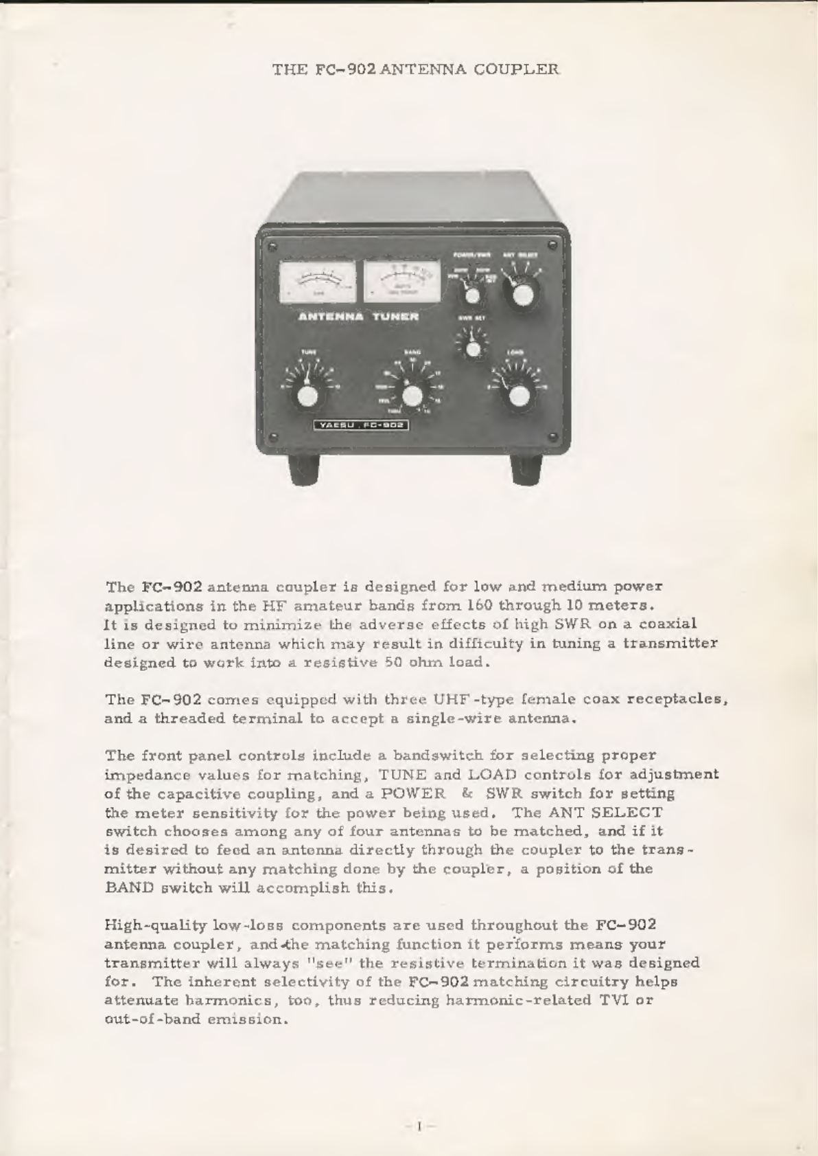
Yaesu FC-902 User manual

INSTRUCTION
MANUAL
FC-902
YAESU
MUSEN
CO.,
LTD.
TOKYO,
JAPAN

THE
FC-902
ANTENNA
COUPLER
The
FC-902
antenna
coupler
is
designed
for
low
and
medium
power
applications
in
the
HY
amateur
bands
from
160
through
10
meters.
It is
designed
to
minimize
the
adverse
effects
of
high
SWR
on
a
coaxial
line
or
wire
antenna
which
may
result
in
difficulty
in
tuning
a
transmitter
designed
to
work
into
a
resistive
50
ohm
load.
The
FC-902
comes
equipped
with
three
UHF-type
female
coax
receptacles,
and
a
threaded terminal
to
accept
a
single-wire
antenna.
The
front
panel
controls
include
a
bandswitch
for
selecting
proper
impedance
values
for
matching,
TUNE
and
LOAD
controls
for
adjustment
of
the
capacitive
coupling,
and
a
POWER
&
SWR
switch
for
setting
the
meter
sensitivity
for
the
power
being
used.
The
ANT
SELECT
switch
chooses
among
any
of
four
antennas
to
be
matched,
and
if
it
is
desired
to
feed
an
antenna
directly
through
the
coupler
to
the
trans-
mitter
without
any
matching
done
by
the
coupler,
a
position
of
the
BAND
switch
will
accomplish
this.
High-quality
low-loss
components
are
used
throughout
the
FC-902
antenna
coupler,
and-the
matching
function
it
performs
means
your
transmitter
will
always
''see"'
the
resistive
termination
it
was
designed
for.
The
inherent
selectivity
of
the
FC-902
matching
circuitry
helps
attenuate
harmonics,
too,
thus
reducing
harmonic-related
TVI
or
out-of-band
emission,

FC-902
SPECIFICATIONS
FREQUENCY
COVERAGE
Input
impedance
Max.
variation
in
load
impedance
Maximum
transmitter
power
Power
meter
calibration
scales
Insertion
loss
Rear
panel
antenna
connections
Dimensions
Weight
SWR
calibration
160mL
1.8-2.0
MHz
160mH
1.9-2.4
MHz
80m
3.5
-4.0
MHz
40m
7.0-7.5
MHz
30m
10.0-10.5
MHz
20m,
14,0-14.5
MHz
lim
18.0-18.5
MHz
15m
21.0-21.5
MHz
12m
24.5-25.0
MHz
10m
28.0-29.7
MHz
50-75
ohms
50
ohm
in:
10-250
ohms
75
ohm
in:
18-300
ohms
500
W
PEP
@
50
ohms
25
W,
250
W,
500
W
0,5
dB
max.
3
coaxial
"UHF"
type
1
single
wire
terminal
208
(L.)x152(H)x324(D)
mm.
6.5
kg.
To
4:1SWR

FRONT PANEL
CONTROLS
TUNE
The
TUNE
control
is
a
dual
capacitor
to
provide
capacitive
adjustment
of
the
coupling
between
the
transmitter
and
the
impedance
established
by
the
BAND
switch
and
the
LOAD
control,
The
TUNE
and
LOAD
controls
are
adjusted
for
minimum
SWR.
BAND
switch
The
BAND
switch
selects
the
inductance
required
to
accomplish
matching
on
the
band
in
question,
The
operator
should select
the
BAND
switch
position
which
best
covers
the
portion
of
the
band
being
used,
The
DIREGT
position
of
the
BAND
switch
connects
the
transmitter
directly
to
the
antenna,
bypassing
the
FC-902
matching
circuitry,
but
permitting
measurement
of
the
SWR
on
the
line
at
that
point.
SWR
SET
This
control
is
used
to
calibrate
the
SWR
METER:
the
SWR
may
be
read
accurately
by
adjusting
the
SWR
SET
control
for
full
deflection
of
the
FWD
POWER
meter
with
the
POWER
&
SWR
switch
in
the
SWR
SET
position.
LOAD
The
LOAD
control
is
connected
to
a
variable
capacitor
which
adjusts
the
coupling
between
the
antenna
feedline
and
the
impedance
presented
by
the
BAND
switch
inductor
and
the
TUNE
control.

ANT
SELECT
This
switch
selects
the
antenna
to
be
matched.
The
operator
has
the
choice
of
one
of
three
coax-fed
antennas
or
a
single
wire
antenna.
POWER
&SWR
switch
This
switch
is
used
to
select
the
proper
sensitivity
of
the
FWD
POWER
raeter
for the
power
being
used,
and
to
provide
calibration
for
the
measurement
of
SWR,
FWD
POWER
meter
The
FWD
POWER
meter
reads
the
output
power
on
three
scales
of
25
watts,
250
watts,
and
500
watts
maximum.
SWR
meter
When
calibrated,
this
meter
provides
accurate
measurement
of
SWR
for
purposes
of
adjusting
the
LOAD
and
TUNE
controls
for
the
best
match,
CM
COUPLER
UNIT
2500)
(500)

REAR
PANEL
CONNECTIONS
ANT
1,
ANT
2,
ANT
3
These
three
female
UHF
-type
connectors
will
accept
the
coaxial
feedline
from
the
antenna.
As
well,
a
dummy
load
such
as
the
YAESU
YP-150
may
be
attached
to
one
of
these
connectors
for
tuning
or
test
purposes.
WIRE
This
threaded
terminal
accepts
a
single-wire
antenna
such
as
the
"Windom"
type.
GND
This
terminal
should
be
connected
to
a
good
earth
ground
so
as
to
provide
a
DC
path
to
ground
for
stray
currents,
and
to
reduce
“RF
in
the
shack"
and
ground
loops,
etc.,
that
may
make
antenna
matching
difficult.
This
is
particulary
important
in
the
case
of
certain
types
of
single-wire
antennas.
INPUT
The
INPUT
connector
is
another
female
UHF
receptacle
for
connection
between
the
FC-902
and
the
RF
output
connector
of
the
transmitter
or
transceiver,
COAXIAL
CABLE
\
pA
ord
HEED
rh
TRANSCEIVER/
TRANSMITTER
YP-150
anta
anni]
/
1
“3
al
asta
witt/on>wyput
ant
10)
(9)
6)
COAXIAL
CABLE
COAXIAL
CABLE

The
reader
is
referred
to
Fig.
1,
which
contains
the
approximately
correct
positions
of
the
BAND,
LOAD,
and
TUNE
controls
for
a
50
ohm
load
impedance,
such
as
that
presented
by
a
dummy
load.
A
dummy
load
is
extremely
useful
for
tuning
up
a
transmitter
in
preparation
for
adjustment
of
matching
of
an
antenna.
If
the
control
positions
shown
in
Fig.
1
are
utilized
in
conjunction
with
a
50
ohm
dummy
load,
only
very
minor adjustments
of
the
TUNE
and
LOAD
controls
will
be
necessary
for
a
perfect
match.
Of
course,
a
50-ohm
dummy
load
should
require
no
matching
for
a
perfect
match
to
a
50-chm
transmitter
output,
but
this
information
is
presented
because
the
control
positions
in
Fig.
1
represent
useful
starting
points
for
matching
unknown
impedances.
‘The
following,
then,
is
a
step-by-step
procedure
to
follow
for
the
matching
of
an
antenna
feedline
that
has
not
been
matched
previously.
1)
Tune
up
the
transmitter
in
the
normal
way
into
a
50-ohm
dummy
load
(if
50
ohm
coax
is
used
between
the
transmitter
and
the
FC-902)
or
other
resistive
50
ohm
termination.
Reduce
the
gain
control
on
the
transmitter
to
a
minimum,
and
place
the
transmitter
in
"standby"
for
the
moment,
2)
Place
the
BAND,
LOAD,
and
TUNE
controls
in
the
positions
indicated
in
Fig.
1
for the
frequency
at
which
the
line
is
to
be
matched.
Place
the
ANT
SELECT
switch
in
the
position
which
corresponds
to
the
rear
panel
connector
of
the
antenna
to
be
matched.
Place
the
POWER
&
SWR
switch
in
the
SWR
SET
position,
and
place
the
SWR
SET
knob
in
the
12:00
position.
3)
It
is
desirable
to
make
preliminary
matching
adjustments
with
as
little
transmitter
output
power
as
possible.
Place
the
transmitter
in
the
"transmit"
condition,
and
slowly
advance
the
output
level
until
deflection
of
the
FWD
POWER
meter
is
observed.
Adjust
the
SWR
SET
control
to
line
up
the
meter
needle
of
the
FWD
POWER
meter
with
the
SWR
SET
position
at
the far
right
end
of
the
FWD
POWER
meter,
using
the
minimum
power
necessary
to
accomplish
this.
With
the
needle
in
the
SWR
SET
mark
of
the
FWD
POWER
meter,
the
SWR
meter
will
accurately
read
the
SWR.
4)
Adjust
the
TUNE
control
for
minimum
reading
on
the
SWR
meter.
If
necessary,
adjust
the
SWR
SET
control
and/or
trans-
mitter
power
to
ensure
proper
calibration.
Once
the
"dip"
has
been
found
using
the
TUNE
control,
move
the
LOAD
control
either
to
the
left
or
right,
by
a
small
amount.
Adjust
the
TUNE
control
for
a
"dip"
again,
and
if
the
SWR
improves
(again,
make
sure
that
you
are
reasonably
well
calibrated)
move
the
LOAD
control
slight-
ly
more
in
the
same
direction.
Again
"dip"
the
TUNE
control,
and
continue
this
procedure
until
no
further
improvement
is
noted.
If
the initial
direction
of
adjustment
of
the
LOAD
control
worsened
the
SWR,
move
it
an
equal
direction
from
the
starting
point
IN
THE
OPPOSITE
DIRECTION
and
follow
the
above
procedure
with
sive
adjustment
of
the
TUNE
and
LOAD
controls.
suce

———
5)
Once
the
initial
procedure
has
been
followed
to
yield
a
near-
perfect
match,
the
POWER
&
SWR
switch
may
be
placed
in
the
position
which
most
closely
corresponds
to
the
transmitter
output
power
expected.
The
transmitter
may
then
be
adjusted
for
full
power
(some
adjustment
of
the
transmitter
load
and
tune
controls
may
be
necessary
during
matching
adjustments),
and
the
FC-902
LOAD
and
TUNE
controls
may
be
adjusted
to
yield
zero
deflection
of
the
SWR
meter.
When
the
POWER
&
SWR
switch
is
not
calibrated
with
the
SWR
SET
controls,
the
SWR
meter
will
not
accurately
read
the
SWR,
but
it
will
indicate
minimum
reflected
power.
NOTES
ON
ANTENNA
MATCHING
1)
It
is
very
important
that
the
maximum
time
limits
during
tune-up
conditions
for
the
transmitter
are
not
exceeded.
This
is
particularly
important
when
the
transmitter
is
being
used
at full
power.
2)
It
should
be
noted
that
any
matching
performed
by
the
FC-902
in
the
shack
will
have
no
effect
on
the
losses
due
to
SWR
on
the
coaxial
line
between
the
FC-902
coupler
and
the
antenna,
The
operator
should
consult
one
of
the
popular
antenna
handbooks
to
determine
whether
or
not
matching
between
the
coaxial
line
and
the
antenna
must
be
performed
at
the
antenna.
For
exemple,
a
100-foot
length
of
RG8A/U
coax
typically
has
a
loss
(with
1:1
SWR
between
it
and
antenna)
of
less
than
1
dB
at
21
MHz.
Lf
this line
is
operated
with
a
3:1
SWR
due
to
a
low
or
high
antenna
impedance,
the
loss
due
to
SWR
will
increase
roughly
0.5
dB,
an
imperceptible
degradation
as
compared
to
the
1:1
condition.
In
this
case,
attempts
to
reduce
the
3:1
SWR
at
the
antenna
end
would
serve
no
useful
purpose
as
far
as
reducing
losses
in
the
coax,
through
matching
with
the
FC-902
would
improve
the
ance
presented
to
the
transmitter
output
cirenitry.
However
if
a
500-foot
length
of
the
above
cvax
were
used
instead
of
only
100
feet,
somewhat
more
than
1dB
of
loss
would
occur
in
the
coax
due
to
the
3:1
SW,
possibly
justifying
further
matching
attempts
at
the
anteara,
3)
Whea
using
a
transceiver
such
as
the
FT-301D
which
has
protection
for the
output
transistors
against
high
SWR,
it
can
be
seen
that
the
matching
action
of
the
FC-902
will
ensure
that
a
59
ohm
load
is
presented
to
the
output
circuitry,
thus
ensuring
full
transmitter
power.
4)
It
may
be
useful
for
the
operator
to
record
in
a
notebook
the
proper
TUNE
and
LOAD
positions
for
a
particular
anteana
for
qaick
r
fabricate
reace,
Alternatively,
apptopriate
labels
may
be
and
applied
2o
the
FC-902
front
panel
showing
the
tions
of
the
TUNE
and
LOAD
controls.
proper
pt

PARTS
LIST
al
2
DIAGRAM


K4XL's
-@
BAMA
This
manual
is
provided
FREE
OF
CHARGE
from
the
“BoatAnchor
Manual
Archive”
as
a
service
to
the
Boatanchor
community.
It
was
uploaded
by
someone
who
wanted
to
help
you
repair
and
maintain
your
equipment.
If
you
paid
anyone
other
than
BAMA
for
this
manual,
you
paid
someone
who
is
making
a
profit
from
the
free
labor
of
others
without
asking
their
permission.
You
may
pass
on
copies
of
this
manual
to
anyone
who
needs
it.
But
do
it
without
charge.
Thousands
of
files
are
available
without
charge
from
BAMA.
Visit
us
at
http://bama.sbc.edu
Table of contents
Other Yaesu Antenna manuals