This guide helps users understand and deploy ICCN antennas including ANT-245GHZ, ANT-DISH-24,
and ANT-OMNI-12. It contains instructions for set-up and best use with an ICCN compatible access
point.
Intended audience
This manual is designed to be used by network managers, administrators, and technicians who are
responsible for installing networking equipment in enterprise and service provider environments.
Knowledge of telecommunication and Internet protocol (IP) technologies and advanced knowledge of
LAN/WLAN networking is assumed.
Documentation
Product and support documentation consists of a variety of manuals, installation guides, videos,
knowledge articles, sample designs, and troubleshooting and FAQ guides to assist you with the
deployment of your new and innovative solution.
These and other documents are available for download at http://www.intcomcorp.com/warranty-
support/. To view PDF files, use Adobe Acrobat Reader®5.0 or newer. Download Acrobat Reader®for
free from the Adobe website: www.adobe.com/products.
Contact information
Phone: (951)934-0531
E-mail: support@intcomcorp.com
sales@intcomcorp.com
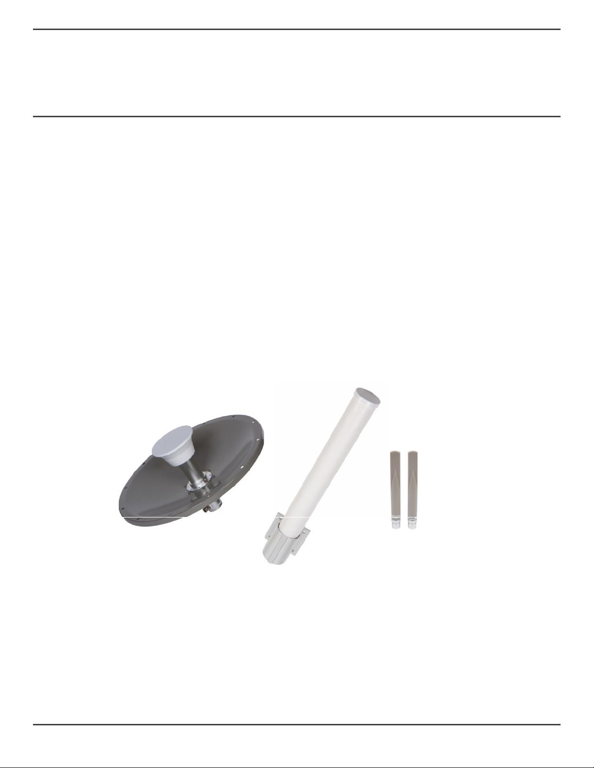
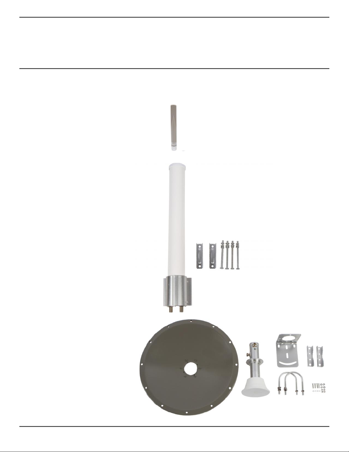
This guide helps users understand and deploy ICCN antennas including ANT-245GHZ, ANT-DISH-24,
and ANT-OMNI-12. It contains instructions for set-up and best use with an ICCN compatible access
point.
Intended audience
This manual is designed to be used by network managers, administrators, and technicians who are
responsible for installing networking equipment in enterprise and service provider environments.
Knowledge of telecommunication and Internet protocol (IP) technologies and advanced knowledge of
LAN/WLAN networking is assumed.
Documentation
Product and support documentation consists of a variety of manuals, installation guides, videos,
knowledge articles, sample designs, and troubleshooting and FAQ guides to assist you with the
deployment of your new and innovative solution.
These and other documents are available for download at http://www.intcomcorp.com/warranty-
support/. To view PDF files, use Adobe Acrobat Reader®5.0 or newer. Download Acrobat Reader®for
free from the Adobe website: www.adobe.com/products.
Contact information
Phone: (951)934-0531
E-mail: support@intcomcorp.com
©2018 ICC Networking. All rights reserved.
2