TrackMen VioTrack R+ User manual

VioTrack R+
Optical camera tracking-system for virtual graphics
A product of TrackMen
U G
Version 1.1 (EN), May 2021

VioTrack R+ User Guide
TrackMen GmbH 2
© 2019 TrackMen Ltd. All rights reserved. Except as otherwise permitted
by TrackMen Ltd., this publication, or parts thereof, may not be reproduced
in any form, by any method, for any purpose.
Disclaimer
THIS PUBLICATION AND THE INFORMATION CONTAINED HEREIN
IS MADE AVAILABLE BY TRACKMEN LTD. “AS IS.” TRACKMEN LTD.
DISCLAIMS ALL WARRANTIES, EITHER EXCLICK OR IMPLIED,
INCLUDING BUT NOT LIMITED TO ANY IMPLIED WARRANTIES OF
MERCHANTABILITY OR SUITABILITY FOR A PARTICULAR PURPOSE
REGARDING THESE MATERIALS.
Published by:
Dillenburger Straße 97L
51105 Cologne
Germany
TrackMen GmbH
VioTrack R+ User Guide
1 Table of Contents
1 Daily use 1
1.1 Switch on .....................................................................................1
1.2 User interface ...............................................................................2
1.3 Switch on error diagnostics .......................................................3
2 Real Environment 6
2.1 Reconstructions ..........................................................................6
2.2 Initialization: Create new reconstructions ...............................7
2.3 Rework: Expanding reconstructions .........................................9
2.4 Error diagnosis initialization ....................................................10
3 Maintenance 13
3.1 Mounting Slave Camera: Calculation of Oset ......................13
3.2 Master Camera Lens ..................................................................16
3.3 Data connection to the tracking workstation .........................21
3.4 Remote access ...........................................................................21
4 Advanced settings 22
4.1 Network .......................................................................................22
4.2 Conguring transmitters ..........................................................22
4.3 Delay of tracking data ...............................................................23
4.4 Coordinate system .....................................................................25
5 Appendix 26
5.1 System design ............................................................................26
VioTrack R+ User Guide
TrackMen GmbH 1
Daily use
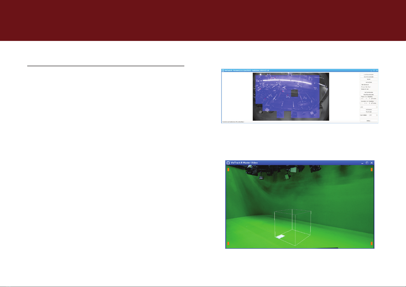
Illustration 1-2: Master Video with wireframe cube
Illustration 1-1: Tracking with decisive points in VioTrack R
2 Daily use
2.1 Switch on 1/1
For the daily start-up of the system, please use the following steps:
1. Start master and slave cameras: the slave camera is switched on
and o via the power supply which may be provided by the master
camera.
2. Set the camera at starting position: for the best possible start,
the camera is to be placed approximately in the position where the
rst keyframes were taken.
3. Start Tracking Workstation: the system boots and automatically
starts the preset VioTrack. Three processes are then started:
3.a VioTrack Master
3.b VioTrack Master Video
3.c VioTrack R
4. The system will automatically restore the last reconstruction:
the video of the slave camera will be examined, searching for the
pattern of the last used reconstruction and the camera will locate its
position based on the detected points.
5. The system now sends the real-time tracking data to the
graphics engine: In the VioTrack R window, the known part of the
video is marked in blue because reliable points are detected there
(illustration 1-1). In the VioTrack Master video, the C key can be used
to display a wireframe cube which is on the ground at the origin
(illustration 1-2) and becomes larger and smaller when zooming
analogously to the real video.

TrackMen GmbH 2
Daily use VioTrack R+ User Guide
2.2 User interface
VioTrack launches a specially congured
Linux client that is reduced to the essential
functions needed for operation.
The interface components are named as
follows:
1. Taskbar: displays menus, which can
be opened and processes which are
currently running. Here: VioTrack R
Master Video (minimized), VioTack
R Master (conguration window,
minimized) and VioTrack R (window
open).
2. System log: displays a real-time
log with information and any error
messages which may occur.
3. VioTrack R: the slave process of
camera tracking with an embedded
video. The master process and the
associated video are displayed in
separate open windows.
Illustration 1-3: VioTrack R User Interface with Open VioTrack R Slave Process
1.
2.
3.

VioTrack R+ User Guide
TrackMen GmbH 3
Daily use
Illustration 1-5: VioTrack R Camera Settings
Illustration 1-4: VioTrack R Window without Slave Camera Video
2.3 Switch on error diagnostics 1/3
2.3.1 No image of slave camera
The Slave Camera is a network camera which must register with the
computer and the VioTrack process. The boot process may take a few
minutes.
If the camera starts after the VioTrack process or during the running
tracking process, it may not have been recognized. This can easily be
xed by restarting the image source: Illustration 1-6: Status-LED of the slave camera
2. In the VioTrack R window, click on Settings.
3. In the Settings window, click to the tab labeled Camera.
1. Make sure that the Slave camera has fully booted. Status-
LED (Illustration 1-6) illuminates either blue or green constantly
throughout.
4. Click on Restart Image Source.

VioTrack R+ User Guide
TrackMen GmbH 4
Daily use
Illustration 1-8: Load reconstruction under optimized conditions with Load Reconstruction
Illustration 1-7:Indicator of incorrect recovery: light blue image areas, as they occur only
moderately here, predominate in the image
2.3.2 Graphics are incorrect / not located at all
Check that the reconstruction could be restored plausibly. If the actual
scenery diers greatly from that in the reconstruction (changed lighting,
etc.) or the camera is far from known patterns or is panned in unknown
directions, this may result in incorrect detection of values. Please carry out
the following steps:
1. Restore the reconstructed scenery: switch to the on-air lighting
situation, switch o working lights.
2. Move the camera to the approximate starting position of the
reconstruction.
3. In the VioTrack R window, click on Load Reconstruction and select
the reconstruction you wish to apply.
If the scenery has changed permanently or the current lighting
situation should be used for an alternative, selectable show
conguration, a new reconstruction must be created and saved.
See section 3.2.
2.3 Switch on error diagnostics 2/3
VioTrack R+ User Guide
TrackMen GmbH 5
Daily use
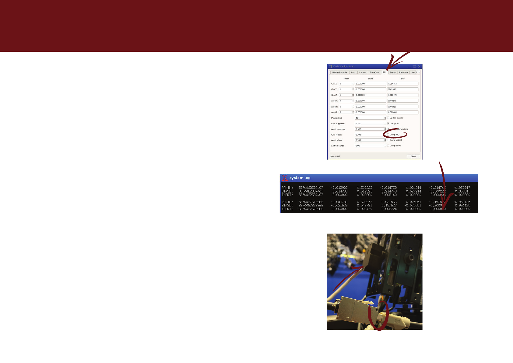
Illustration 1-10: System Log Display with correctly attached IMU data with Dump IMU-
option enabled.
Illustration 1-9: IMU tab in VioTrack Master window
2.3 Switch on error diagnostics 3/3
2.3.3 Graphic sluggish / rushes ahead
Check that the IMU is working correctly.
1. In the event of any irregularities when switching on, it may not have
entered operating mode correctly. Check if data is available: activate
Dump IMU in the IMU tab of the VioTrack R Master window. If data is
available, number columns run through the System Log. This option
can be turned o again after checking procedure is completed.
Illustration 1-11: Cable connection of the IMU (Small case on the tracking camera)
2. If the data is unavailable, nothing is displayed in the system log. In
which case, Start the VioTrack Master Process anew by means
of (Re-)Start VioTrack R In DIAG Menu. Please check the IMU Data
again.
3. If the data still does not appear, check cable connections.
Disconnecting and reconnecting the connection could help.

VioTrack R+ User Guide
TrackMen GmbH 6
Real Environment
Illustration 1-13: Reconstruction as a point cloud. Below the already located oor as a grid.
The yellow line shows the camera movement between the keyframes.
Illustration 1-12: Slave video with intact tracking. The blue crosses show stable tracking
points.
3 Real Environment
3.1 Reconstructions
VioTrack R studies the real environment through an automatic process and
stores the resulting reconstruction in a 3D point cloud. The system will
continually examine the slave video for this known pattern and determine
the camera pose from their position towards it.
The detection works by means of corners and edges, which can be
identied clearly in the image from several perspectives. These points are
called feature points.
If the position of these points changes because the objects are moved
or illuminated dierently, they will no longer be available for tracking. If the
changes become increasingly excessive, the pattern can no longer be
reliably detected, and the recovery will fail.
Various reconstructions, for example, for dierent studios or lighting
moods, can be created and saved to be able to switch between them more
conveniently (see section 2.3.2).

VioTrack R+ User Guide
TrackMen GmbH 7
Real Environment
Illustration 1-14: Video after reset in segmenter mode (black and white) with detected
markers
3.2 Initialization: Create new reconstructions 1/2
To create a new reconstruction, VioTrack R+ uses VioTrack markers which
are installed as physical reectors or displayed on an LED display as a
xed reference. The following steps are performed:
1. Start VioTrack R+.
2. Press Reset in the VioTrack R window: the system will reinitialize:
search for the VioTrack pattern and create a new reconstruction.
Illustration 1-15: Set automatic keyframes by moving through the room. Indicators for set
keyframes light up green in the video.
3. Learn: Slowly move the camera through the entire room to be used
by the camera for broadcast.
• Several keyframes should be taken which include the VioTrack
markers (at least 4).
• Fast movements must be avoided.
• The slave camera should always see as much known reference
as possible, to be able to put new information in correct relation
(about two thirds of the image should display blue tiles).
• Only pan or tilt movements hardly provide new 3D data and are
to be combined with movement.

VioTrack R+ User Guide
TrackMen GmbH 8
Real Environment
4. Check the results in the VioTrac k R window: are blue crosses
regularly distributed in the image throughout the tracking area? If it’
is less than expected, then is it possibly too dark.
Illustration 1-16: Result: The wire frame cube is back at its intended position
Illustration 1-17: Fair number of tracking points in slave video
Illustration 1-18: Finish the reconstruction creation
5. Check the result in the VioTrack R Master Video window: Press C to
display the wireframe cube. Is it where it is supposed to be?
6. If the results are good, press Save Reconstruction in the VioTrack
Rwindow.
7. Switch o the further gathering of points by removing the check
of the Allow Extension option in the VioTrack R window.
3.2 Initialization: Create new reconstructions 2/2

VioTrack R+ User Guide
TrackMen GmbH 9
Real Environment
Illustration 1-20: Collect new keyframes based on the loaded reconstruction
Illustration 1-19: Load Basic Reconstruction and Enable Allow Extension
3.3 Rework: Expanding reconstructions
If signicant parts of the scenery change or new areas of the studio are
opened up, which are either not yet used or under-sampled, existing
reconstructions can be extended:
1. Start VioTrack R+.
2. Click Load Reconstruction in the VioTrack R window.
3. Select the basic reconstruction you want to extend. After
selection, the system will automatically try to nd its way into the
reconstruction.
4. Make sure that location is successful within the loaded scene.
Especially since the environment may have already changed or
areas have not yet been reconstructed, it is recommended to move
the camera near the starting position, where the reconstruction was
started. See also Section 2.3.2.
5. Enable the Allow Extension option.
6. Continue to study the environment as described in section 3.2 in
points 3 to 7. It is sucient to drive through the new areas.

VioTrack R+ User Guide
TrackMen GmbH 10
Real Environment
Illustration 1-22: Extension of the reconstruction by means of the camera with already
known image contents in sight. Pan and Tilt alone do not bring new 3D information if they
are not connected to motion.
Illustration 1-21: Reconstruction by recognizing points from two dierent perspectives.
Points contained in both keyframes are determined in 3D.
3.4 Error diagnosis initialization 1/3
Should the initialization fail, this may be caused by the following reasons:
1. Too many reference points have been lost during the walk-through
the detection stage. The results are then inconclusive.
1.a Try to slow down the speed of the pan and tilt of the camera.
new information must always be associated with already
reconstructed information.
1.b While driving through try to avoid areas where little to no content
has been placed, for example, a lot of green screen or extremely
dark areas.

VioTrack R+ User Guide
TrackMen GmbH 11
Real Environment
2. Brightness may be an issue. Corners must be suciently high in
contrast. The VioTrack markers must be recognizable as clear,
individual points and rings.
Illustration 1-23: Adjust the brightness of the camera. Switch to the normal display mode.
Illustration 1-24: VioTrack R is in initialization mode. Open the settings.
2.b The detection of the feature points and that of the VioTrack
markers is evaluated in two dierent display modes. For the
overall brightness of the image, switch to Image render mode
Standard in the marker tab.
3.2.1 Error diagnosis initialization 2/3
2.a In the VioTrack R window, click Settings...
2.c Switch to Camera tab. The brightness of the video can be
adjusted using Exposure time. It should not exceed 4000us.
2.d Further brightness can be obtained by selecting gain. This can
be set as a standard of up to 10dB but should not be increased
above 15.

VioTrack R+ User Guide
TrackMen GmbH 12
Real Environment
Illustration 1-26: Switch to Segmentdisplay mode and adjust the Threshold until the markers
are detected by the system and drawn yellow.
Illustration 1-25: Clearly detected markers are drawn in yellow and displayed with their code
2.e Adjust the detection of the VioTrack markers to the new
brightness. Select the marker tab and switch to the Segmenter
render mode.
3.2.1 Error diagnosis initialization 3/3
2.f Customize the Theshold. The markers should appear white and
be clearly recognizable as rings or lled circles. For fully visible
markers, a yellow drawing and a number are displayed.

VioTrack R+ User Guide
TrackMen GmbH 13
Maintenance
Illustration 1-28: Exampleofaxingthecalibrationpatterforthecameraoset;thesteel
door oers a at surface.
Illustration 1-27: Position and orientation of the slave camera to the master camera must
be known.
4 Maintenance
In general, VioTrack does not need to be calibrated regularly unless
signicant changes are made to the environment or hardware.
For changes to the environment, see section „3 Real Environment“.
Changes to the hardware may aect:
4.1 Mounting Slave Camera: Calculation of
Oset 1/3
Since the position and orientation is determined by means of an additional
sensor camera, the oset between the two cameras must be determined
and added.
If, for any reason, the position of the slave camera to the master camera
is manipulated, follow these steps:
1. Place the calibration pattern rmly on a perfectly at surface. The
alignment is recognizable by the three rings in each pattern and
rotated as in illustration 1-28.

VioTrack R+ User Guide
TrackMen GmbH 14
Maintenance
Illustration 1-30: Selection of lens calibrations.
Illustration 1-29: Oset Calculator for calculating the oset between master and slave
camera.
2. Exit VioTrack using STOP VioTra c k in the DIAG menu.
3. Start the Oset Calculator of the TOOLS menu.
4. Turn the master lens to the maximum wide angle and set the focus
to innity.
5. Make sure the current lens calibrations are selected. (see illustration
1-29)
When does a new lens calibration need to be created? The
slave camera is primarily calibrated by TrackMen and no longer
needs to be manipulated. Thus, the calibration remains valid. The
calibration of the master camera must be renewed when the lens
and the camera head have been separated and reassembled.
5.a To change the calibration le, click on Settings...
4.2 Calculation of oset 2/3
5.b In the Settings window, switch to the master or slave tab
respectively and select the current le from the Calibration le-
Drop-Down menu.

VioTrack R+ User Guide
TrackMen GmbH 15
Maintenance
Illustration 1-32: Save the changes to the VioTrack R Master.
Illustration 1-31: Create shots with recognized patterns in both cameras.
6. Align the camera so that the lower pattern is visible to the master
camera and the upper pattern can be recognized by the slave
camera. If the pattern is correctly detected, green lines, and blue
and red dots are drawn. Furthermore, a green check mark appears
Collinear: under both videos.
7. Take a shot with the Add Sample button. The camera and pattern
must be unmoved to prevent mismatching of the recording instants.
8. Repeat points 5 and 6 from varying distances and angles until you
have taken about 8 samples.
9. Calculate the oset with Get Oset Transformation.
10. Check the result: colored crosses are projected onto the dots in
the slave video image. Blue means a small recalculation error, while
red means a higher one. Most of the crosses should be blue or
green.
11. If the result is satisfactory, click Write Oset Transformation. If it
is bad, quit the program and try again.
12. Exit the Oset Calculator with the X at the top right-hand corner
of the window.
13. Launch VioTrack from the DIAG menu.
14. Click on Save in the VioTrack R Master window, to retain the
changed oset.
Unlike lens calibration, it is not necessary to capture the entire video
image and ll it with green dots during the oset shots!
4.2 Calculation of oset 3/3

VioTrack R+ User Guide
TrackMen GmbH 16
Maintenance
Illustration 1-34: Visualization of Center Shift 2: After zooming out, the graphic has moved
away from the object without moving the camera.
Illustration 1-33:Visualization of Center Shift 1: Graphic and real object t in the tele.
4.2 Master Camera Lens
The properties of the lens of the Master Camera are taken from a detailed
calibration via its zoom and focus paths. However, due to manufacturing
tolerances, the properties will vary slightly each time the lens is mounted.
The following factors should be considered:
4.2.1 Center Shift
The lens will never be exactly in the middle of the chip and therefore will
not zoom exactly to the center of the image (see Illustration 1-33 and
Illustration 1-34). This variance must be reported in the graphic. After each
lens installation, detailed in the steps listed below.

VioTrack R+ User Guide
TrackMen GmbH 17
Maintenance
1. Position the camera in a xed position
Illustration 1-35: Center a corner in the image. Position the wireframe cube and a real object
so that they meet at this corner.
Illustration 1-36: Show the cuboid (key C).
4.2.1 Center Shift 1/2
2. Switch to the VioTrack R Master Video window and see the cuboid
(key C).
3. Switch to the VioTrack Master window and open the Cuboid tab.
Position the wireframe cube using Center X and Center Y, and
frame it in the center of the image.
4. Completely Zoom in exactly on a corner. Center the corner in the
image. Activate The Center Cross for help. Now do not move the
camera for the rest of the operation.
5. Place a real object, like a at piece of paper, so that a corner is
right on the corner of the cube. Fine adjustment can be performed
by shifting the graphic with Center X and Center Y.
Table of contents


