Tranberg TEF 1058 User manual

Installation and operating manual - TUM5134
TEF 1058 Heat Trace Thermostat
Installation Manual
TEF 1058 Heat Trace Pipe & Wall Mounted Thermostat
Zone 1, Zone 2 & Safe Area
Document properties (TUM5134)
Revision
Comment
Revision date
Approved
I
New design
07.03.2022
CKR

Installation and operating manual - TUM5134
TEF 1058 Heat Trace Thermostat
Installation and operating manual
Contents
Document properties (TUM5134) ............................................................................................................................ 1
Warnings and risk levels.......................................................................................................................................... 3
General information................................................................................................................................................. 3
Marking and intended use ....................................................................................................................................... 4
Special conditions for safe use................................................................................................................................ 5
Technical data ......................................................................................................................................................... 5
Product description.................................................................................................................................................. 5
Transport and storage ............................................................................................................................................. 5
Mounting and installation......................................................................................................................................... 6
Mounting of wall mounted type (fig. 01) .............................................................................................................. 6
Mounting of pipe mounted type (fig. 03).............................................................................................................. 7
Temperature sensor............................................................................................................................................ 7
Termination ......................................................................................................................................................... 7
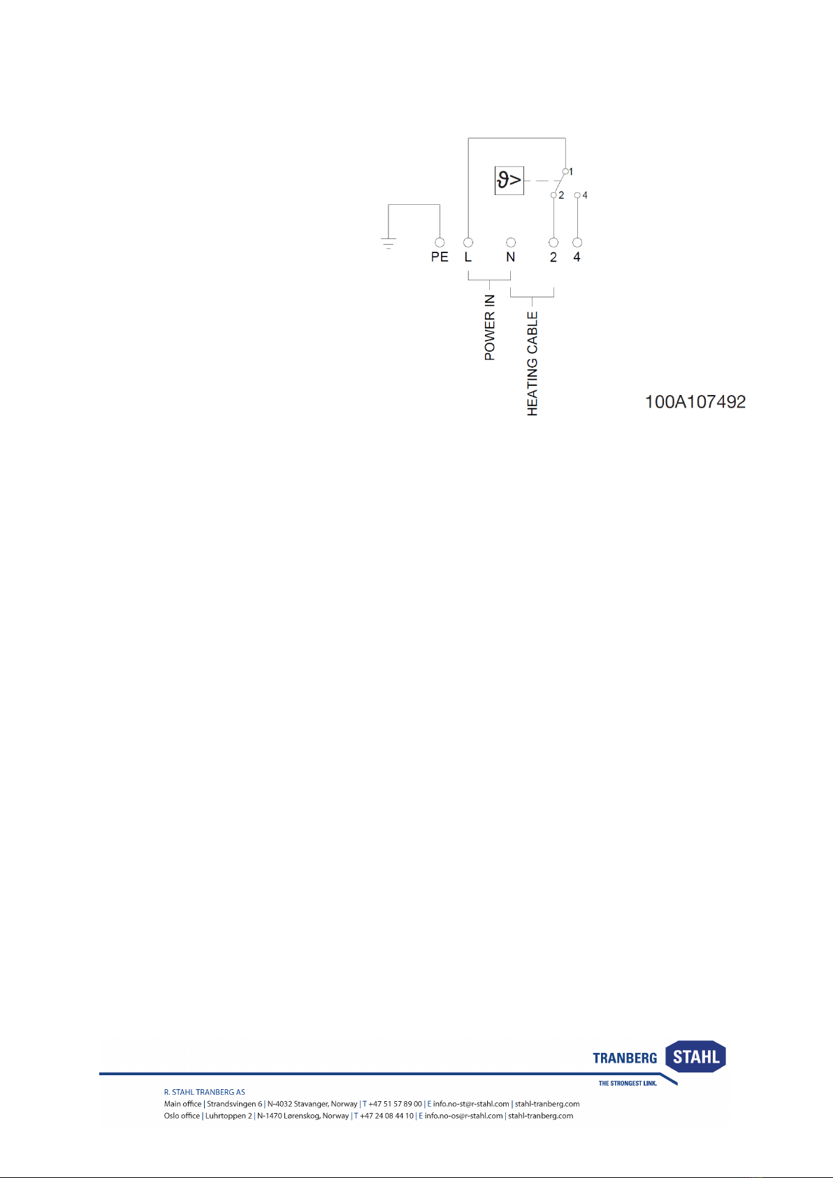
Electrical connections ......................................................................................................................................... 8
Setting the limit value in accordance with the scale: ............................................................................................... 8
Setting the limit value in accordance with installation specific operational characteristic:....................................... 8
Maintenance and cleaning....................................................................................................................................... 8
Disposal................................................................................................................................................................... 9
Compliance/Conformity ......................................................................................................................................... 10

Installation and operating manual - TUM5134
TEF 1058 Heat Trace Thermostat
Warnings and risk levels
DANGER
Non-compliance with the instruction results in risk of severe or fatal injuries to persons
WARNING
Non-compliance with the instruction may result in risk of severe or fatal injuries to persons
CAUTION
Non-compliance with the instruction may result in risk of injuries or damage to equipment
NOTICE
Non-compliance with the instruction may result in reduced lifetime of equipment, malfunctions etc.
General information
Before installation, make sure to read and understand this installation and operating manual.
Observe national assembly and installation regulations.
Always contact the manufacturer if anything is unclear, or if you notice any faults on the product or in this
document.
This installation and operating manual shall be available to anyone operating, installing, inspecting, modifying or
repairing the equipment.

Installation and operating manual - TUM5134
TEF 1058 Heat Trace Thermostat
Marking and intended use
DANGER
Not for use in Zone 0
CAUTION
The empty enclosures of these enclosure series are suitable for the installation of explosion protected
components. The empty enclosures feature a component certificate. Therefore, the equipment may only be
used for its intended use. Improper or impermissible use or non-compliance with the information in these
operating instruction voids any warranty. Changes to the equipment that impair the function of the equipment
or the explosion protection are not permissible.
Ex marking: Ex de IIC Gb
Ex eb IIC
Ex e mb IIC Gb
T6/T5/T4
For use in Zone 1, Zone 2 & Safe Area

Installation and operating manual - TUM5134
TEF 1058 Heat Trace Thermostat
Special conditions for safe use
DANGER
Special conditions for safe use are critical conditions to maintain the explosion protection of the equipment.
These shall be adhered to in all cases and under all circumstances.
•Follow this manual for installation and maintenance.
•Only qualified personnel are allowed to perform installation and maintenance tasks to this equipment.
•The junction box is equipped for termination of heat tracing and is ready for installation when leaving the
production facilities of R. Stahl Tranberg AS.
•Changes made to the product which do not confirm to the approvals of this equipment, is a safety
violation. The manufacturer is under no circumstances responsible for personal injuries, death or any
other damage caused by such activities.
•Any damage done to the equipment during transportation is not the responsibility of R. Stahl Tranberg
AS.
•If the content is not complete, file a claim to the producer immediately.
Technical data
Property
Value
Value
Explosion protection
Ex d e IIC Gb
T6 / T5 / T4
Ex eb IIC
Ex e mb IIC Gb
Tamb:
-50°C …+50°C (Silicone)
-20°C…+40°C
Nominal voltage
230 VAC
Main switching capacity:
16 (2.5)A PF=1(0.6) (N/C contact)
6.3 (2.5)A PF=1(0.6) (N/O contact)
Ingress protection
IP66 / IP67*
* IP67 without drain plug
Max. cable diameter
6 mm2
Housing material
Acid proof stainless steel
Product description
TEF 1058 thermostat is according to NORSOK requirements and is used for a various range of applications such
as hazardous areas, chemical and petrochemical industries, industrial plants (for frost protection or temperature
maintenance).
Transport and storage
•Transport and store the equipment only in the original packaging
•Store the equipment in a dry and vibration free place
•Do not drop!

Installation and operating manual - TUM5134
TEF 1058 Heat Trace Thermostat
Mounting and installation
DANGER
Incorrect mounting and installation may lead to explosion risks, risk of falling objects, risk for electric shock and
risk for equipment malfunction. In turn, this can lead to severe damage and/or injuries.
Mounting of wall mounted type (fig. 01)
•Mount the thermostat junction box by at least two Pcs. M6 bolts placed diagonally on a wall or proper
supported rack.
•Remove dust protection or stopping plugs and install selected gland. Use stopping plugs for unused
entries. Only certified cable glands and stopping plugs may be used. Select gland according to the cable
diameter used.
•Strap the transition unit to pipe with pipe straps.
•Assembly the flexible conduit according to the special gland. see fig. 02

Installation and operating manual - TUM5134
TEF 1058 Heat Trace Thermostat
Mounting of pipe mounted type (fig. 03)
•Mount the thermostat junction box either standing or hanging to pipe with pipe straps.
•Remove dust protection or stopping plugs and install selected gland. Install the drain plug at the lowest
point. Use stopping plugs for unused entries. Only certified cable glands and blinds may be used. Select
gland according to the cable diameter used.
Temperature sensor
The sensor must be strapped in good thermal contact with the pipe or equipment. In addition to general mechan-
ical protection, the sensor must be protected so that the thermal insulation cannot be tapped between the sensor
and the heated surface. The sensor is normally fixed to pipe or object by use of aluminum tape. Other methods
could be thermowells suitable for the application.
Note!
The widened area of the capillary tube, shall be clamped by the cable gland sealing ring. The sealing ring is not
dimensioned for the Ø1,5 mm capillary tube.
Termination
In order to maintain the mode of protection, connect the conductors with special care. The isolation must reach up
to the terminals and do not damage the conductor. Termination of heat cables must be according to cable
specification given by the supplier of these. Tighten all the terminals, also those vacant. Reinstall the lid and tight
bolts firmly with suitable tool by hand force. Over tightening may impair the protection category.

Installation and operating manual - TUM5134
TEF 1058 Heat Trace Thermostat
Electrical connections
L-N: Power cable / Input
2-N: Heating cable / output N/C contact
4-N: Output N/O contact
Setting the limit value in accordance with the scale:
Use the internal scale to set the limit value on the setpoint adjuster. (Do not exert mechanical pressure to the
setpoint value spindel).
Setting the limit value in accordance with installation specific operational
characteristic:
•Heat the temperature probe-in the unit- to the required limit temperature (temperature adjustment time at
least 5 minutes), recording and monitoring the exact temperature on the temperature probe with a
librated reference measuring device.
•Turn the setpoint adjuster from the scale limit value towards the scale start value, determine the required
switching point position (circuit opens and electrical circuit 1-4 is closed).
Maintenance and cleaning
•Maintenance according to national regulations and company practice.
•Before opening the junction box make sure that the power is disconnected.
•Servicing the junction box is done be checking the intactness of the junction box, gasket and glands. If
necessary lubricate the lid bolt threads with grease type Renolit Unitemp 2 from Fuchs.
•If repair or overhaul is necessary this may only be done with Tranberg spare parts.
•Modification of the JB or change of design are not permitted, except for installing additional glands and
terminals according to the approval of the JB.
•Clean only with a damp cloth, water and mild detergents. Avoid chemicals with high or low pH,
abrasives, high pressure washer, strong detergents, solvents, petroleum- or alcohol based cleaning
agents and similar. Avoid any corrosive media.

Installation and operating manual - TUM5134
TEF 1058 Heat Trace Thermostat
Disposal
CAUTION
This equipment or part of this equipment is considered EE-Waste, and shall be handled accordingly
•Observe national and local regulations and statutory regulations regarding disposal
•Separate materials when sending it for recycling
•Ensure environmentally friendly disposal of all components
•No component or packaging shall end up in the ocean during any stage of the product’s lifetime

Installation and operating manual - TUM5134
TEF 1058 Heat Trace Thermostat
Compliance/Conformity
•Presafe 14ATEX4124
•IECEx PRE 14.0001
•Applicable standards 2014/34/EU ATEX Directive: EN 60079-0:2012 [ 2018], EN 60079-1:2007 [2014],
EN 60079-7:2007 [2015/A1:2018], EN 60079-18:2009 [2015/A1:2017]
•Document no DoC: TDC3131
Other manuals for TEF 1058
2
Table of contents
Other Tranberg Thermostat manuals