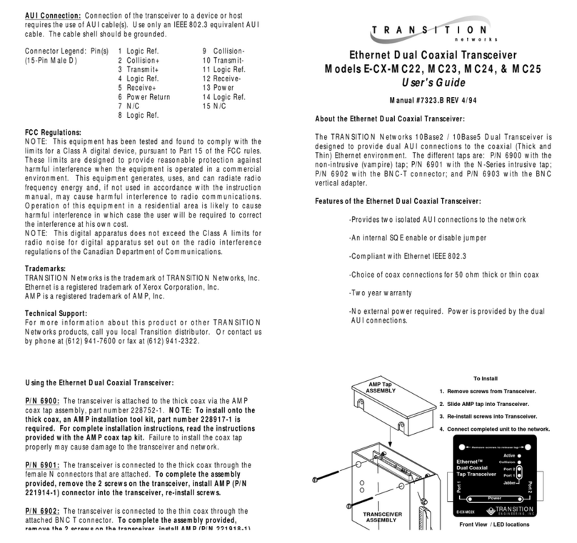
AUI (DB-15) Interface
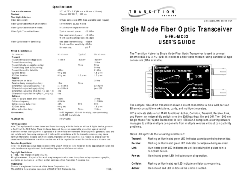
Parameter Minimum Typical Maximum
Transmit
Transmit threshold voltage level: -140mV -170mV -190mV
Transmit turn on delay: 100ns
Transmit steady propagation delay: 15ns 50ns
Transmit loop back start up delay: 500ns
Transmit turn off to data idle: 400ns 2100ns
SQE test delay: 0.6 µ sec 1.6 µ sec
SQE test duration: 0.5 µ sec 1.0 µ sec 1.5 µ sec
Receive
Receive turn on delay: 350ns
Receive steady propagation delay: 15ns 50ns
Differential output voltage (RX(-/+)): (+/-)550mV (+/-)1200
Differential output voltage (col(-/+)): (+/-)550mV (+-)1200
Differential output rise time (RX(-/+), col(-/+)): 4ns
Differential output fall time (RX(-/+), col(-/+)): 4ns
Collision
Time for SQE to deact. after collision: 450ns 700ns
Collision frequency: 8.5MHz 11.5MHz
Collision pulse duty cycle: 40% 50% 60%
SQE test delay: 0.6 µ sec 1.6 µ sec
Jabber activation delay: 20ms 70ms 150ms
Cable Specifications
The physical characteristics of the media cable must meet or exceed IEEE 802.3
specifications.
Fiber Cable
Multimode Cable Recommended: 62.5 / 125 µm multimode fiber
Optional: 100 / 140 µm multimode fiber; 85 / 125 µm multimode fiber
50 / 125 µm multimode fiber;
Singlemode Cable Recommended: 9/125 µm singlemode fiber
Bit error rate: 1 0-9
850 nm MULTIMODE
Fiber-optic Transmitter Power: min: -19.0 dBm max: -14.0 dBm
Fiber-optic Receiver Sensitivity: min: -32.5 dBm max: -14.0 dBm
Typical
Maximum Cable Distance*: 2 kilometers (6,600 feet)
1300 nm MULTIMODE
Fiber-optic Transmitter Power: min: -19.0 dBm max: -15.0 dBm
Fiber-optic Receiver Sensitivity: min: -32.5 dBm max: -14.0 dBm
Typical
Maximum Cable Distance*: 5 kilometers (66,000 feet)
1300 nm SINGLEMODE
Fiber-optic Transmitter Power: min: -27.0 dBm max: -10.0 dBm
Fiber-optic Receiver Sensitivity: min: -34.0 dBm max: -14.0 dBm
Typical
Maximum Cable Distance*: 20 kilometers (66,000 feet)
*Actual distance dependent upon physical characteristics of network installation.
The fiber optic transmitters on this device meet Class I Laser safety requirements per
IEC-825/CDRH standards and comply with 21 CFR1040.10 and 21CFR1040.11.
E-FRL-MC05
6
Technical Specifications
Standards IEEE 802.3
Case Dimensions 3.8 x 1.65 x .94 inches (95 x 42 x 24 mm)
Weight 3.5 oz. (99.2 g)
Environment Tmra*: 0-40°C (32° to 104° F )
Humidity 10-90%, non condensing
Altitude 0-10,000 feet
Power 11.4 - 16.5 VDC,
175 mA (typical), 300 mA (maximum)
Warranty Lifetime
*Manufacturer’s rated ambient temperature.
Product is certified by the manufacturer to comply with DHHS Rule 21/CFR,
Subchapter J applicable at the date of manufacture.
CAUTION: Visible and invisible laser radiation when open. Do not stare into
the beam or view directly with optical instruments.
CAUTION: Use of controls, adjustments or the performance of procedures
other than those specified herein may result in hazardous radiation exposure.
7
Declaration of Conformity
Name of Mfg: Transition Networks
6475 City West Parkway, Minneapolis MN 55344 USA
Model: AUI/10BASE-FL Transceiver
Part Number: E-FRL-MC05, E-FRL-MC05(SC), E-FRL-MC05(SM),
E-FRL-MC05(L)
Regulation: EMC Directive 89/336/EEC
Purpose: To declare that the
E-FRL-MC05
to which this declaration refers is in
conformity with the following standards.
EMC-CISPR 22: 1985 Class A; EN 55022: 1988 Class A; EN 50082-1:1992;
EN 60950 A4:1997; IEC 801.2, IEC 801.3, and IEC 801.4; IEC 950
I, the undersigned, hereby declare that the equipment specified above conforms to the above
Directive(s) and Standard(s).
_November 11, 1999_____
Stephen Anderson, Vice-President of Engineering Date
