Travis Industries CoolSmart PB 36 User manual

Page 1 of 12 17602034- 7/11/19 © Travis Industries, Inc.
Compatibility
ProBuilder 36 Clean Face
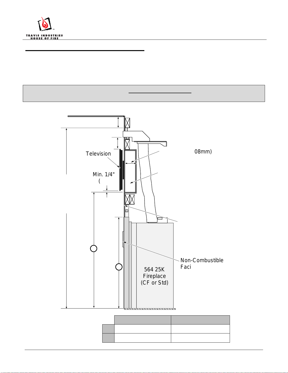
564 25K (Standard or CleanFace)
Packing List
• (1) Convection Manifold (with grill and mounting brackets pre-attached)
• (2) 5” Diameter Aluminum Flex Ducts
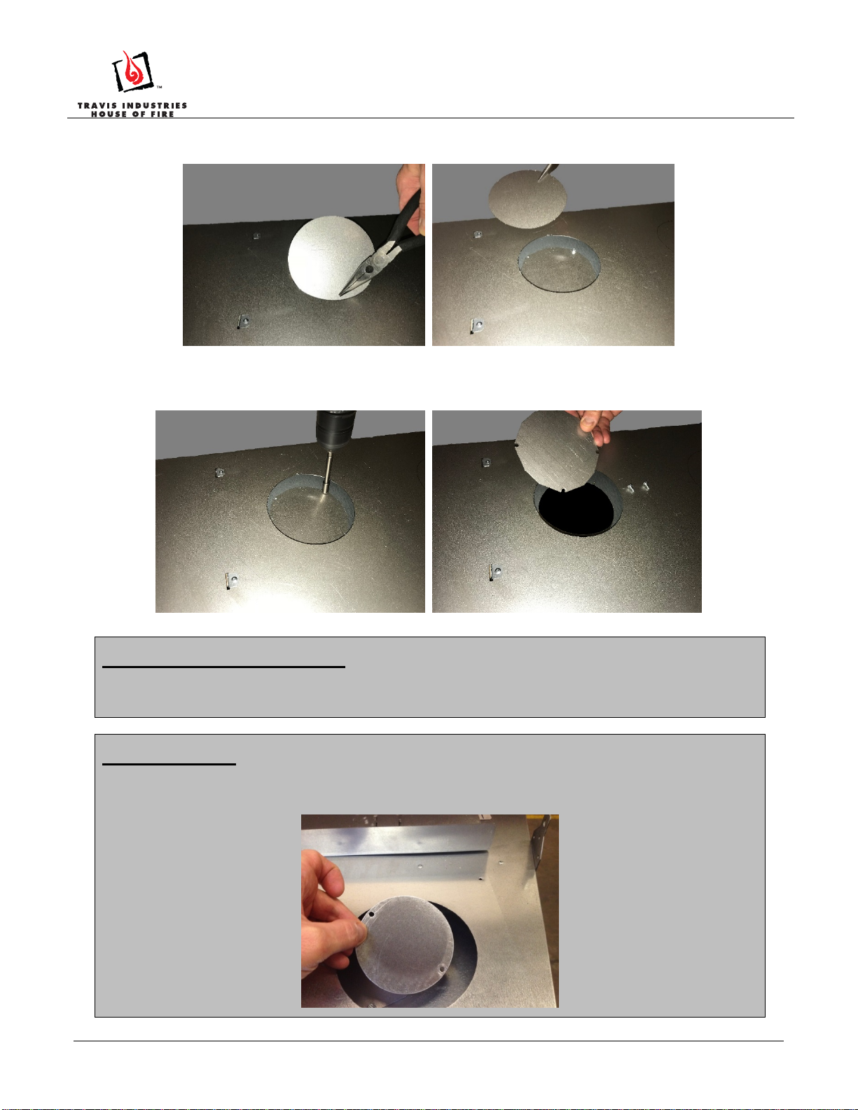
• (2) Starter Collars
• (12) Self-Drilling Tek Screws
• (2) Convection Air Deflectors (Used for the PB 36 ONLY – see below)
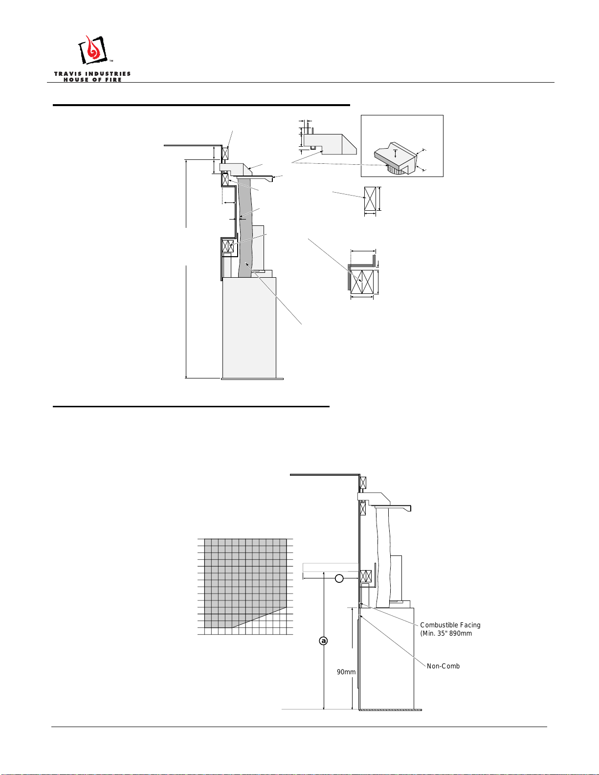
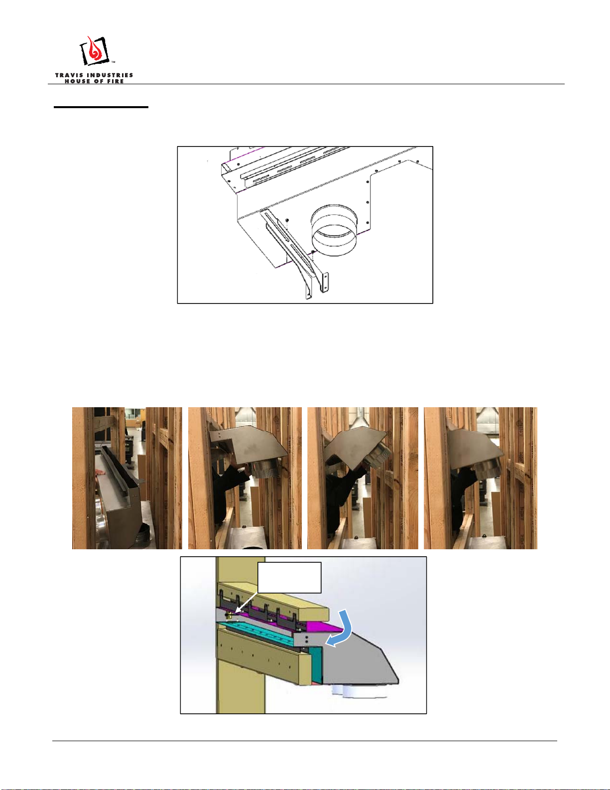
Convection Air Deflectors- ProBuilder 36 CF ONLY
The 2 deflectors must be installed prior to attaching the CoolSmart kit. After removing the cover plates, install the
deflectors as shown below.
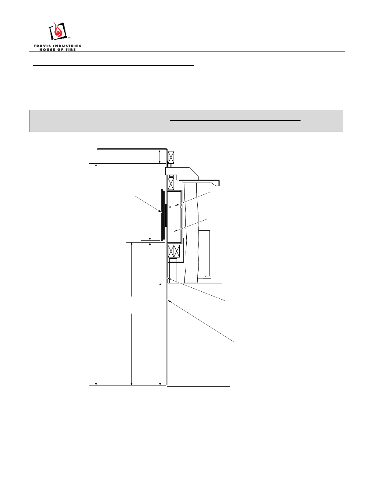
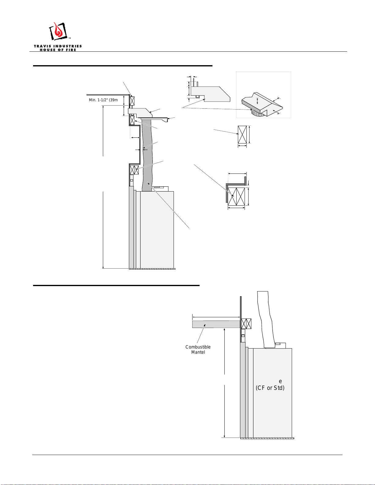
Grill and Manifold Dimensions
The grill may be installed over the facing to
provide an aesthetic opening for the
convection outlet. (2) 8-32 x 1-1/2” screws
attach the trim to the upper manifold. This
allows variable thickness of finish material.
Dimensions
a b c d e
35-7/8” (912mm) 2-7/8” (74mm) 1-1/4” (32mm) 34-7/8” (886mm) 1-3/4” (45mm)
Deflectors are installed here.
Note how the
deflectors points
downward to the
rear.
PB 36 & 564 25K CoolSmart TV
(sku# 98900778)
564 25K NOT AVAILABLE IN AUSTRALIA

PB 36 & 564 25K CoolSmart TV
(sku# 98900778)
Page 2 of 12 17602034- 7/11/19 © Travis Industries, Inc.
PB 36 CF Installation Overview
The CoolSmart system is designed to redirect the convective heat of the fireplaces from the front of the unit, just
above the glass, to a location higher on the wall. The use of this kit allows for reduced clearances to televisions
and a recessed cavity above the fireplace. When using this kit, disregard the framing dimensions in the manual
and follow the framing instructions included in this instruction sheet. See the installation manual for further
requirements.
When used on the PB 36 CF, this kit allows for the non-combustible facing height to be reduced. See
illustration below for details.
Min. 1-1/2" (39mm)
Max. 120"
(3048mm)
Min. 73-3/4"
(1690mm)
Non-Combustible
Facing Only
Ceiling
ProBuilder
36 CF
Fireplace
Optional Recessed Pocket
Min. 35"
(889mm)
Combustible Facing
Allowed
Min. 45-1/2"
(1156mm)
Max. 3-1/2"
(89mm)
Television
Min. 1/4"
(7mm)
to the top of
the zero-clearance box

PB 36 & 564 25K CoolSmart TV
(sku# 98900778)
Page 3 of 12 17602034- 7/11/19 © Travis Industries, Inc.
PB 36 CF Installation Requirements
PB 36 CF Reduced Mantel Height
When using this kit, disregard the combustible mantel requirements in the manual and follow the requirements
shown to the right. If you wish to place a TV above the mantel, it must meet the following requirements:
Minimum 1” air gap behind TV to wall.
The mantel must extend 2” in front of the TV and 1” to both sides.
1-1/4" (32mm)
1-3/4" (45mm)
3/4" (20mm)
3/8" (10mm)
Min. 3-1/2" (89mm)
Max. 1-1/2" (39mm)
M
in. 1-1/2" (39mm) Manifold
3-3/4"
(96mm)
Max. 120"
(3048mm)
Min. 73-3/4"
(1874mm)
5" (127mm) Alum. Flex Duct (included)
Ceiling
Upper Manifold Framing
Lower Manifold Framing
Max. 3-1/2"
(89mm)
Manifold Support Bracket
Fireplace Header
Min. 1" (26mm) Clearance from
Flex Duct to Combustibles
Min. 3-1/2" (89mm)
Max. 3" (77mm)
Min. 1/2" (13mm) *
Max. 3-1/2" (89mm)
Min. 1-1/4" (32mm)
Clearance from Top, Sides
and Back to Combustibles
ProBuilder
36 CF
Fireplace
*This area may be supported using
1” strips pf non-combustible material
spaced a minimum of 12”
b
Maximum Mantel Depth (b) With
CoolSmart TV Kit
Mantel Height
Above Base (a) With
CoolSmart TV Kit
46" (1169mm)
0" (0mm)
1" (25mm)
2" (51mm)
8" (203mm)
7" (178mm)
6" (152mm)
5" (127mm)
4" (102mm)
3" (76mm)
9" (229mm)
10" (254mm)
11" (279mm)
12" (305mm)
45" (1143mm)
44" (1118mm)
43" (1093mm)
42" (1067mm)
41" (1042mm)
40" (1016mm)
47" (1194mm)
39" (991mm)
37" (941mm)
38" (966mm)
36" (916mm)
35" (890mm)
34" (864mm)
Non-Combustible
Facing Only
ProBuilder 36
CF Fireplace
Min.
35"
890mm
a
Combustible Facing
(Min. 35" 890mm above
base of fireplace)

PB 36 & 564 25K CoolSmart TV
(sku# 98900778)
Page 4 of 12 17602034- 7/11/19 © Travis Industries, Inc.
PB 36 CF Framing the Chase
When using this kit, disregard the framing dimensions in the manual and follow the framing instructions shown
below.
Max. 120"
3048mm
Min. 73-3/4"
1874mm
3-3/4"
96mm
Upper Manifold Framing
Lower Manifold Framing
8-1/2"
216mm
Bottom of Upper
Manifold Framing
Braces for Manifold
Support Brackets
PB 36CF37-3/8" 950mm
41"
1042mm
15-1/4"
388mm
PB36CF
26-1/2" 674mm

PB 36 & 564 25K CoolSmart TV
(sku# 98900778)
Page 5 of 12 17602034- 7/11/19 © Travis Industries, Inc.
564 25K Installation Overview
The CoolSmart system is designed to redirect the convective heat of the fireplaces from the front of the unit, just
above the glass, to a location higher on the wall. The use of this kit allows for reduced clearances to televisions
and a recessed cavity above the fireplace. When using this kit, disregard the framing dimensions in the manual
and follow the framing instructions included in this instruction sheet. See the installation manual for further
requirements.
When used on the 564 25K, this kit allows for the mantel height to be reduced. See “564 25K Reduced Mantel
Height” on page 6 for details.
564 25K CleanFace 564 25K Standard
a 41-3/8”(1051mm) 41-3/8”(1051mm)
b 33-1/8” (842mm) 30-1/4”(769mm)
Optional Recessed Pocket
Combustible Facing
Allowed
564 25K
Fireplace
(CF or Std)
Non-Combustible
Facing Only
Ceiling
Max. 4-1/4" (108mm)
Television
Min. 1/4"
(7mm)
a
b
Max. 120"
(3048mm)
Min. 70-7/8"
(1801mm)
Min. 1-1/2" (39mm)
Min. 1-1/4" (32mm)

PB 36 & 564 25K CoolSmart TV
(sku# 98900778)
Page 6 of 12 17602034- 7/11/19 © Travis Industries, Inc.
564 25K Installation Requirements
564 25K Reduced Mantel Height
When using this kit, disregard the combustible
mantel requirements in the manual and follow the
requirements shown to the right.
If you wish to place a TV above the mantel, it must
meet the following requirements:
Minimum 1” air gap behind TV to wall.
The mantel must extend 2” in front of the
TV and 1” to both sides.
1-1/4" (32mm)
1-3/4" (45mm)
3/4" (20mm)
3/8" (10mm)
Min. 3-1/2"
(89mm)
Max. 1-1/2" (39mm)
Min. 1-1/2" (39mm)
Manifold
3-3/4"
(96mm)
Max. 120"
(3048mm)
Min. 70-7/8"
(1801mm)
5" (127mm) Alum. Flex Duct
(included)
Ceiling
Upper Manifold Framing
Lower Manifold Framing
Max. 4-1/4"
(108mm)
Manifold Support Bracket
Fireplace Header
Min. 1" Clearance from
Flex Duct to Combustibles
Min. 3-1/2"
(89mm)
Max. 3"
(77mm)
Min. 1/2" (13mm)
Max. 4-1/4" (108mm)
Min. 1-1/4" (32mm)
Clearance from Top, Sides
and Back to Combustibles
564 25K
Fireplace
(CF or Std)
Max. 12" (305mm)
Min.33-1/4"
(844mm)
564 25K
Fireplace
(CF or Std)
Combustible
Mantel

PB 36 & 564 25K CoolSmart TV
(sku# 98900778)
Page 7 of 12 17602034- 7/11/19 © Travis Industries, Inc.
564 25K Framing the Chase
When using this kit, disregard the framing dimensions in the manual and follow the framing instructions shown
below.
564 25K Standard 564 25K CleanFace
a 37-3/4” (959mm) 38-3/4” (985mm)
b 17-1/2” (445mm) 19-3/8” (493mm) Flush
18-7/8” (480mm) Extended
c 37-1/4” (947mm) 37-1/4” (947mm)
Max. 120"
3048mm
Min. 70-7/8"
1801mm
3-3/4"
96mm
Upper Manifold Framing
Lower Manifold Framing
8-1/2"
216mm
Bottom of Upper
Manifold Framing
Braces for Manifold
Support Brackets
26-1/2" 674mm
ab
c

PB 36 & 564 25K CoolSmart TV
(sku# 98900778)
Page 8 of 12 17602034- 7/11/19 © Travis Industries, Inc.
Installation
1 Remove the grill from the manifold (2 screws hold it in place).
2 Remove the rear-mounting brackets by loosening 1/4" screws and sliding it out of the keyhole slots.
3 Determine the desired location of the bottom of the convection air outlet. Install a horizontal framing
member at the desired height, parallel to the header. Install a second horizontal framing member 3-3/4”
above the first. These two framing members will support the upper convection manifold in the following
steps.
4 Hold the upper convection manifold with the outlet facing the back of the framing members installed in the
previous step. Tilt the outlet of the manifold downward until the outlet of the manifold and the two
mounting tabs can fit between to two framing members. Slide the outlet into the gap and allow it to sit
level again. The two mounting tabs will support the manifold.
Mounting
tabs

PB 36 & 564 25K CoolSmart TV
(sku# 98900778)
Page 9 of 12 17602034- 7/11/19 © Travis Industries, Inc.
5 Secure the manifold to the upper framing using screws (not included).
6 Re-attach the two rear mounting brackets (removed in step 6) to the bottom of the convection manifold.
Leave the screws loose so the brackets can be positioned to the back of the chase. Secure the brackets
to the chase using screws (not included). Tighten the screws securing the brackets to the manifold.
7 Remove the knockouts from the top of the fireplace.
8 Use snips or diagonal cutters to snip the tab on the knockouts. Press on the far side away from the tap to
pop the edge of the knockout up.
Secure to framing

PB 36 & 564 25K CoolSmart TV
(sku# 98900778)
Page 10 of 12 17602034- 7/11/19 © Travis Industries, Inc.
9 Grab on to the knockout with pliers and bend it back and forth until the remaining tabs break free.
Discard the knock out plate.
10 Under each knock out plate, you will find a cover plate held in place with (2) ¼” screws. Use a nut driver
or drill with an extension to remove the (2) screws. Reach in and remove the cover plate. You may
discard the plates.
PROBUILDER 36CF ONLY
If installing a ProBuilder 36CF, you must install the deflectors prior to installing the starter collars (see
page 1 for details).
564 25K ONLY
You will need to remove a third cover plate on each side. Remove the 2 screws holding the cover plate in
place. Reach in and remove the cover plate. You may discard the plates.

PB 36 & 564 25K CoolSmart TV
(sku# 98900778)
Page 11 of 12 17602034- 7/11/19 © Travis Industries, Inc.
11 Insert a starter collar into each of the (2) holes that were uncovered in the previous step and bend the
tabs to secure the starter collar to the fireplace.. Seal the joints with silicone caulk or aluminum (U.L.
181A-P) tape.
12 Install the fireplace into the framed chase. See section “Installation” in the manual.

PB 36 & 564 25K CoolSmart TV
(sku# 98900778)
Page 12 of 12 17602034- 7/11/19 © Travis Industries, Inc.
13 Stretch the included flex to its maximum length. Measure the distance between the starter collars on the
fireplace and the inlets on the convection manifold. Cut the flex to the appropriate length and install
between the fireplace and the manifold. Secure using (3) screws at every connection and seal the joints
with silicone caulk or aluminum (U.L. 181A-P) tape.
14 Cover the face of the fireplace and the outlet of the manifold to ensure no construction debris or
sheetrock dust enters the unit.
15 Once all finish work is complete around the outlet of the manifold, install the outlet grill assembly using
the two included screws (one at each end). The grill assembly will overlap finish material up to 1-1/2”
thick. See fireplace installation manual for finishing details.
NOTE: The manifold opening protrudes 7/16" (12mm) proud of the framing. The wall may be finished to the
opening if you do not wish to use the grill trim.
Self-Drilling
Screw
This manual suits for next models
1
Table of contents